converting tail lights
Printed From: the12volt.com
Forum Name: Lights, Neon, LEDs, HIDs
Forum Discription: Under Car Lighting, Strobe Lights, Fog Lights, Headlights, HIDs, DRL, Tail Lights, Brake Lights, Dashboard Lights, WigWag, etc.
URL: https://www.the12volt.com/installbay/forum_posts.asp?tid=135078
Printed Date: March 28, 2026 at 9:54 PM
Topic: converting tail lights
Posted By: riggz
Subject: converting tail lights
Date Posted: October 16, 2013 at 9:10 AM
I am converting my 09 Suburban's incandescent tail lights to LED tail lights from an Escalade. The Suburban uses separate bulbs for the brake and turn signals while the Escaldr uses the same LEDs for both. Others have already completed this conversion with success by using a Hopkins trailer 5 to 4 wire converter and 50 watt resistors. My only issue with this (thanks to my OCD) is that this makes the tail light turn signals flash opposite of the front and side mirrors when the brake is applied. I believe the converter sees the momentary feed from the turn signal wire while the brake is applied it cuts the power to the led. Is there a simple way to build my own converter that would allow them to always flash with the front regardless if the brake is applied?
Thanks in advance!
-------------
-=riggz
Replies:
Posted By: oldspark
Date Posted: October 17, 2013 at 1:20 AM
Forget the resistors, change your flasher can. Alternatively consider keeping the bulbs and add LEDs, or move the bulbs.
The conversion can be done with a DPDT relay per side (or 1 SPDT and 1 SPST per side) and moving where the flasher can resides - ie, replace with a link; the L/R switch controls the L or R relay, and the flasher can output does to each relay.
I might be able to provide more info if you are still interested.
Posted By: riggz
Date Posted: October 17, 2013 at 1:27 AM
I don't think there is an actual flasher as I believe it is controlled by a computer module. I will double check though. As for the resistors, the new lights I am installing are LEDs built in to the housing (all in one unit) there is no bulb to replace, only the entire unit. I would rather have resistors mounted instead of hiding bulbs somewhere.
-------------
-=riggz
Posted By: oldspark
Date Posted: October 17, 2013 at 1:40 AM
You'll have to find out or decide if you can reposition the flasher signal/can.
Otherwise you need some smart module that samples both brake and flasher signals - maybe an exLED Electrical TPC Module (ver 2 or ver 3 etc) per side though these too may be out of phase.
Posted By: powerslave
Date Posted: October 18, 2013 at 12:59 PM
The problem with LEDS bulbs, is they only allow current to flow one way, they are diodes. Some tail configurations need the Incandescent bulb because it can ground back through the bulb, but not an LED since current can only go one way.
I had a problem like this, using LEDs, so I had to splice in another bulb connector, put a bulbs in, and heat-shrink tube over the bulbs.
Anyhow, if you splice your trailer connector/harness right into the factory wires, and have incandescent bulbs in the trailer, you should not have a problem.
You have three wires at each left and right bulb you want to use:
HI(signal/stop), LOW (running), & GROUND.
You only need one low side (left or right) for both the trailer's running/parking lights, and one ground.
Then, the HI side from left and right, to the harness for the left/right stop/signals on the trailer.
If your trailer has two bulbs on each side, and you want ONE on each side to just be brake, tap into your CENTER HI-MOUNT light, so they only come on with the brakes.
Posted By: oldspark
Date Posted: October 18, 2013 at 7:23 PM
To clarify the first "one way grounding" (thru a LED) in powerslave's first para above, the problem with LEDs is usually that they provide too low a load for current sensitive circuits like flasher cans and blown-bulb detectors.
In other cases, some circuits like cruise controls apparently need to sense closer to 0V than the FWD voltage drop of a LED, but that's only relevant when the "light" is off.
In all cases you merely have to parallel a suitable resistor.
For cruise controls etc, the resistance required depends on the sensing voltage threshold & impedance/resistance.
For flashers and blown-bulb sensors, the resistor(s) need to be similar to the original bulbs. (This obviously negates the use of LEDs for power saving reasons, hence why shunt or programming resistors else software is changed or load-insensitive flashers substituted.)
Apologies for the interrupt, but I just wanted to clarify. I've seen too much rubbish emanating from the idea of "rectified grounding".
Posted By: powerslave
Date Posted: October 19, 2013 at 5:22 PM
The Chevy SSR has the cruise control issue with LEDs.
We also fix the hyper flash, or no flash with thermal flashers, with an a electronic flasher. The van we did, the signals would not work with LEDs (Hazard did), it had a thermal flasher and you need current for that to work. We went to the electronic flasher, and all fixed, no hyper-flash either. You can buy them specifically for LEDs now, they say LED FLASHER on the unit.
The resistors have to be just enough to work, and only use where needed. If the parking light side works fine, then don't use the resistor on that wire, that way, you still benefit from the lower power consumption if you want to leave the lights on for a while. Since you don't sit/party with the brake lights or signals on, then use the resistor on the high side when needed, because your using them when driving; thus droving the alternator is charging the battery anyway.
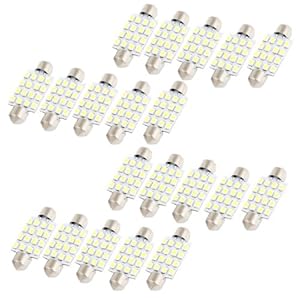
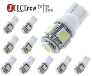
I have been getting great deals on LEDs from Amazon.... I got 20 Festoon panel lights, for under $10.00, each panel has 12 LEDs. ARe they CHEAPLY MADE? You bet, but they're under a lens... I also got TEN 168 type LEDs for under $4.00 + shipping, they all work.
What hurts LEDs is the Manufacturing process. THe more heat applied to put them on the boards or in a circuit, the less they last. 90% of LED failure is due poor/cheap manufacturing. But hell, I got TWENTY of them, enough to replace one every year if need be. On and Off cycles DO NOT effect an LED like a filemant bulb.
Posted By: powerslave
Date Posted: October 19, 2013 at 5:26 PM
Actually, each 562 panel has 16 LEDS, forgot, four rows of four LEDs.
Each 194 has five LEDs, one forward, one on each side.
I got plenty of them... Did my whole car with LEDs...
Posted By: oldspark
Date Posted: October 19, 2013 at 7:42 PM
Though the above doesn't solve the OP's problem, to clarify powerslave's reply - the resistors are placed across (or parallel) to the LEDs though they can be placed anywhere.
Remember - the resistors are to give the circuit the same loading as the original bulbs hence the proper current for thermal flashers (or non-reprogrammable electronic flashers), and fool check sensors into thinking the "bulbs" are still ok.
That has no effect on alternators etc since the LEDs and resistors look the same as the OEM lighting.
In some cases, lower power (higher Ohmage) resistors may be ok. EG - a cruise control may get away with a 150 Ohm 1W or 680 Ohm 1/4W instead of one or more 10 Ohm 20W etc (across brake-light LEDs).
Posted By: powerslave
Date Posted: October 25, 2013 at 8:49 PM
I would have ADDED the post above yours to the one above THAT, but I can't EDIT. IT was not for solving his problem, it was FYI, as part of the post where I explain somethings with new cars and how they work.
Posted By: riggz
Date Posted: November 17, 2013 at 3:24 PM
Ok maybe I wasn't clear in my first post. THanks to all those who have offered advice so far.
My 2009 Suburban has the standard tail lights with one bulb for brake, one bulb for turn signal, and a bulb for reverse. This requires 5 wires to complete: ground, brake, turn, reverse, park. I am swaping out the entire tail light assembly with a new assembly from a Caddilac Escalade that is all LED (except for the reverse bulb). The issue is that the Escalade tail light uses the same LEDs for brake and turn signal. So it only requires 4 wires to complete: ground, brake/turn, reverse, park.
Since they also use different plugs I have gone ahead and assembled new plugs to go in between the body wire harness and the new Escalade tail light with a converter in the middle. I have also included a 50watt 6ohm resistor to simulate a turn signal bulb to prevent hyper flash (which is controlled by the BCM or Body Control Module). I can not just swap out a "flasher can" as it does not exist in this vehicle. I have installed a Hopkins 5 wire to 4 wire electronic tail light converter to make this work and only use one side of the output and it works fine. (Although one of the two converters I purchased was bad and wouldn't pass through the brake light feed.) Really the only thing I need to accomplish is how to pass the brake and turn through and output it as one. If the brake is applied it passes straight through. If the turn signal is applied it passes through and flashes. If the brake AND turn signal are applied it still flashes, but just alternate of the + feed (so it will have to be opposite of the front turn signal.)
I would like to be able to build my own by using a small circuit board and some diodes and relays and then stick it all in a small metal enclosure, but I am not exactly familiar in this area. I can solder and assemble fine but not so good with design. My end goal is to be able to build more of these in order to sell to other's wishing to do the same tail light conversion.
I know a simple automotive relay would "work" but I would like to make this as small as possible and also be as quiet as possible. I tried to break open the bad converter to see what all it had inside, but the way it is built is by pouring the rubbery plastic over their circuit board inside a mold so there is no good way to gain access to their circuit board.
Maybe I should have posted this in a different forum? ------------- -=riggz
Posted By: oldspark
Date Posted: November 17, 2013 at 3:46 PM
IMO you were quite clear. As I said it requires a DPDT relay (or SPDT and SPST), BUT that requires relocation of the flasher can AFTER the flasher switch.
Where that can't be done, delay circuits are required and I've only used programmable stuff for that. (Hence my usual referral to commercial products.)
PS - your flasher switch may feed +12V to "each side" of the BCM in which case the DPDT relay solution should work.
Posted By: oldspark
Date Posted: November 17, 2013 at 8:43 PM
Hold off before buying relays etc. The above was written in haste and I'm about to haste off again.
An SPDT should suffice since the front indicators are not involved.
I was also thinking SPST tho I doubt it - I'll have to think about your set up.
Do you know the current draw of the stop/flasher LEDs? The reason I ask is that a J-FET is perfect for this application, however they have limited current capacity - far too little for traditional bulbs - but I haven't investigated their use for LEDs.
Also if you could confirm that your left-right selector switch supplies +12V to "either" input of the BCM. Ground switching can also be accommodated.
However if it's a single wire control - ie, CAN-bus or other signalling - a simple relay-only solution is not possible.
Posted By: Ween
Date Posted: November 17, 2013 at 10:45 PM
hi,
the turn signal switch supplies ground signals to the BCM, independent left and right inputs. info obtained on GM upfitter website.
mark
Posted By: oldspark
Date Posted: November 18, 2013 at 6:06 AM
THANKS Mark!!
In that case, an SPDT relay. (One per side if applicable.)
86 to fused +12V (see below**)
85 to flasher switch output or BCM input (eg, RHS)
30 to LED +ve
87a to switched brake +12V output
87 to BCM flasher output (eg, RHS)
That assumes both brake and flash are +12V signals (not GND), but that should be true.
And it assumes the BCM does not ground 85.
I suggest a spike quenching diode across the relay coil - ie, a 1N4004 or 1N4007 between 86 & 85; line end to 86 - unless spikes are known to be harmless.
** I said 86 to +12V to allow hazard flashers with IGN off but that depends on how the hazards are switched AND means the relay will be energised whenever the flasher switch is to that side.
If that's an issue, then 86 to IGN +12V (eg from the flasher fuse), but then that rear flasher might not flash with hazards on, and definitely not unless IGN is on.
To explain the above operation assuming it's the RHS:
- normally the brake +12V is connected to the tail LED - ie, 87a to 30.
- when the flasher switch is in its RHS position it grounds the BCM as per normal, and 85 which thus energises the relay.
- the energised relay switches the LED (30) to whatever the BCM is putting out its RHS to flasher lights (87).
The ballast resistor could be placed anywhere from the respective BCM output to the LED +ve, but after 30 is probably better to it hyperflashes if the relay or circuit is faulty.
|