Welcome to the12volt!
And good onya for trying something like this - it's a pretty safe intro that covers a lot of basics - but I'll leave
my praise ramble for now.
You said "12V" LEDs, but 12V LEDs involve a resistor and LED or resistor and a string (group) of LEDs.
LEDs are usually ~2V for red & green, ~3.4V for white, ~4.5V for blue, etc.
And then - yes - wire "strings" or series LEDs where the number of LEDs per string is determined by the SUM of all LED voltages (aka VL) not exceeding the (minimum) supply voltage - eg, 12V. or maybe 11V allowing for a flat battery etc.
A resistor is then used to "drop" the remaining voltage - and also limit the maximum string current.
Typically for white LEDs, a max of 3 per string - ie, 3 x 3.2V or 3 x 3.5V = 9.6V or 10.5V which is
comfortably less than 12V.
If red which were traditionally 1.7V but now 2V or 2.1V, assume 2V hence we could have 6 LEDs = 6 x 2V = 12V (especially in 12V vehicles which are usually more like 12.5V to 14.5V), but we might want to include a resistor so hence maybe only 5 (or 4 or 3) for a "12V" supply.
We need to know the LED current to calculate the resistor value (R = V/I from Ohm's Law V = IR), but your LEDs are probably rated as 20mA. (All LEDs in a string will have the same current thru them.)
NOTE - one resistor per string. The (12V) strings are then paralleled together.
Instead of me rambling, look at
electronicsclub.info - Light Emitting Diodes (LEDs).
There are other good web references and LED resistor calculators.
Maybe then get back with your
preliminary design - how many LEDs with what VL voltages and currents and resistor values and I or others might do a sanity check BEFORE you buy extra components or assemble it etc.
Also note that LEDs are not that critical. Many people wire strings of (say) 6 or 7 reds or 4 whites direct to 12V vehicle systems (ie, 14.4V) without resistors, but resistors should help maintain a more consistent illumination (brightness) with varying voltage as well as help ensure the LED's max current is not exceeded - though less current may not make much practical difference to brightness, and (slight) over-current usually means a shorter life (ie, less than several years) rather than any instant destruction.
As to the EL wire, I presume you mean an ElectroLuminescent display and hence the inverter.
That should simply be a case of wiring the EL to the inverter as per instructions, and the inverter's 12V to the batteries (8 x 1.5V in series = 12V).
The wireless remote I presume is the master on-off switch that sits between the batteries and the rest.
How long the batteries last depends on total current consumption, but that's another issue. However a 12VDC plugpack could be substituted, or even a car battery etc though they are ~12.7V fully charged (and higher when being charged), but the use of LED string resistors should mean that's not a problem. You'd have to check what voltage input the inverter tolerates.
oldspark- thanks for your help. here are the specs of the LEDs i bought on ebay. they list on ebay as 12V...
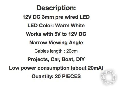
does that mean there's already a transistor in them?
ebay link here:
https://www./itm/50-x-Warm-White-5mm-LEDs-Pre-Wired-Light-12V-20cm-Bulbs-/300516795565
They are white LEDs (usually ~3.5V each) with a resistor.
One problem is that you will be using 3x the current necessary - ie, instead of having one string of 3 LEDs (plus resistor) at 20mA you will have 3 parallel strings of 20mA LEDs consuming 60mA.
Since they are 12V, just connect across your 12V supply.
Resistors and LED calculators are for "raw" LEDs (2V-4V etc), not 12V LED "modules".
OK, got it. Makes sense. I didn't know the difference between a raw LED and a module. Thank you.
Next question (hopefully not too many more..) If I am wiring them all to the 12V source and not in series, then I have about 60 wires that have to connect to 1 wire. what's the best way to accomplish this?
is it a breadboard like this?
https://www.sparkfun.com/products/112
You could provided it's in a stable environment (not vibrating etc).
Or just use any screw type cable joiners.
If they are 20mA LEDs, their total current will be 1.2A.
Though it's a bit hard to estimate, your batteries should last around 1 hour.
OK, i'm in the process of putting it all together and had 2 follow up questions:
1. You wrote about that battery would last about an hour. What if I wanted to use as a wall plug in. Could i just wire up something like this instead of the battery packs?
https://www.amazon.com/Switching-Power-Supply-Adapter-110V-/dp/B006NTNGN0
2. I turned it on as a test, and the overall brightness of the LEDs was TOO BRIGHT. What can i do to decrease their brightness? is there something i can put in the circuit to do this?
thanks,
Sam
From what I can see, both are fine ie, they both handle your 1.2A LED current.