Hi everyone and thanks in advance for your time and advice.
I've researched this topic ad nauseum, and have fried more components than I care to remember in trying to achieve what I believe should be relatively simple. I'm completely frustrated and decided to swallow my pride and ask for some help.
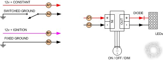
The pic below illustrates my goal - to appropriately power a single set of LED strips (C) using either the constant 12v source (A) or the ignition-only 12v source (B), based on one of the following conditions:
1) Ignition off + door open = lights powered by 12v constant
2) Ignition off + door closed = lights powered by 12v constant
3) Ignition on + door open = lights powered by 12v ignition
4) Ignition on + door closed = lights powered by 12v ignition
Can someone please connect the dots for me? I can easily power the LEDs under any of these conditions, but the switching between configs has me stumped. I've used a variety of relays in a number of configs - either it didn't work at all or it melted beyond recognition by the time I cut the power to it. In my research I've seen mention of the use of MOSFET components and diode-only configs in addition to relay-based switching... Instant parts availability is a bit of a problem, relays are easy enough to procure very quickly and using them seemed easiest but if someone can recommend an alternate but relatively simple solution I would be forever grateful.
Thanks again,
D
A single relay will solve the issue with powering through the ignition switch when the ignition switch is on (see below), but why not power straight from the battery regardless of ignition switch position?
#85 and #87 to ignition 12V+
#86 to ground
#87a to constant 12V+
#30 = 12V+ output
-------------
 the12volt Support the12volt.com
Thanks so much for your response.
The reason for this config is to help mom see her way into her vehicle while avoiding an issue when (not if) she would have otherwise inevitably forgotten to turn the lights off.
And thanks for your question - it made me realize I mistakenly indicated condition 2 should be 12v constant, when it should have said 12v ignition. My assumption was that would be the same as off...but now I'm wondering if that was a poor assumption and if it is responsible for the prior disasters...
Thanks again,
D