LED Flasher with Negative Polarity
Printed From: the12volt.com
Forum Name: Lights, Neon, LEDs, HIDs
Forum Discription: Under Car Lighting, Strobe Lights, Fog Lights, Headlights, HIDs, DRL, Tail Lights, Brake Lights, Dashboard Lights, WigWag, etc.
URL: https://www.the12volt.com/installbay/forum_posts.asp?tid=143428
Printed Date: March 21, 2026 at 2:37 AM
Topic: LED Flasher with Negative Polarity
Posted By: hype6900
Subject: LED Flasher with Negative Polarity
Date Posted: August 02, 2017 at 8:34 AM
I am looking to add an LED flasher to my Indian motorcycle. The goal is to have a switch that would activate the "strobes" when needed but continue to use the signal lights as turn signals/4-way hazards.
The flasher that I was intending to use is the SHO-ME 11.1010SF which has a 4 channel output.
The issue that I am having is that the turn signals due not utilize a conventional "flasher module", but instead receives a grounding signal form the ECM. I know that I can reverse the output polarity of the flasher unit using electromagnetic relays but I do not think the relays would be respond to the input of the flasher unit quickly enough. The flashers would not be used frequently, maybe only 4 or 5 times a year, but when they are used they will be running for long periods of time, possibly a few hours.
So my questions are as follows:
1) Would electromagnetic relays be able to respond quick enough to the pulse and can they be used for this application?
2) Is there any way that I could use solid state relays to reverse the output polarity and could they be used for this application?
Replies:
Posted By: hype6900
Date Posted: August 02, 2017 at 8:35 AM
The vehicle this is being installed in is a 2017 Indian Roadmaster. I do have a full wiring diagram which I can provide if necessary.
Posted By: hype6900
Date Posted: August 02, 2017 at 9:51 AM
An alternative that I just thought of is that I can take the negative pulse from the ECM and convert it to a positive pulse and then just rewire the LED signals. Would this work in a CANBUS system or do you think it would cause a check engine code?
Posted By: hype6900
Date Posted: March 22, 2018 at 4:10 PM
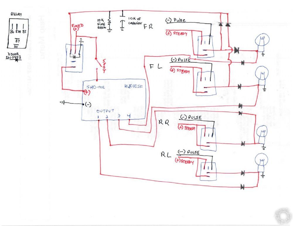
I've come up with a wiring diagram that I think may work for what I am trying to accomplish. I have combined two different types of relay wiring to achieve this.
The first task is to convert the negative pulse from the ECM to a positive output and the the second is to turn the pulsing signal into a steady output.
The idea is that the turn signals will have priority over the LED Flasher. This will allow me to drive with the flashers activated (via switch) but still allow me to use turn signals if needed.
To accomplish this I am using these micro relays along with 1N5408 diodes. The two issues that I am not sure of is 1) is it possible to cut power (i.e. give priority to the blinkers) using the turning a pulsing signal into a steady output and 2) what size capacitor and resistor should I use, would the 10K uf Capacitor and 10K fixed resistor still be appropriate being that there will be no power draw?
Please provide any thoughts/comments.
NOTES:
All turn signals are factory LEDs and I believe they draw around 5 watts.
The stock existing turn signal wires which provide a steady positive and pulsing negative are 22 gauge wires.
Thanks in advance.
Posted By: eguru
Date Posted: March 22, 2018 at 8:11 PM
I'm sure that I haven't followed everything in your posts.
Are the existing LED's being driven on the ground side but you want to convert them to be driven off the +12V side to accommodate the SHO-ME module?
If you can clarify those points, I'm sure we can develop a less messy solution.
Posted By: hype6900
Date Posted: March 23, 2018 at 8:29 AM
Yes, that is exactly what is happening. The existing system runs a steady 12+ through the LED and then the VCM pulses the Negative to ground for the blinker.
Posted By: eguru
Date Posted: March 24, 2018 at 10:08 AM
Try this.
We invert the positive output from the SHO-ME to drive the LEDs (with no change to existing wiring).
We use the turn switch to disable the SHO-ME power input.
Posted By: hype6900
Date Posted: March 26, 2018 at 9:14 AM
Thanks for the reply.
I'll give this a try.
Posted By: hype6900
Date Posted: June 28, 2018 at 2:53 PM
Hi Eguru,
I am finally ready to continue with this project. I have just ordered the COM-12959 and have some follow up questions.
According to your diagram, it looks like you are using a voltage divider circuit to reduce the output of the Sho-Me from 12V to ~11V [(12V X (200k/(20k+200k)) = 10.9] is that correct? If so, according to the datasheet the Vgs is +10,-8. Is it safe to run the gate source at the higher voltage knowing that it will most likely be around 14 Volts when the vehicle is running? Also, what wattage resistors are you using in the above example? Lastly, do you know if the COM-12959 10K resistor that comes with the kit would be the R1 or R2 resister in your above circuit?
I am also assuming that as I am not running power through this I would only connect the Gate, Source to ground, and Drain and the other two pins (System + and Device +) would be empty.
Posted By: hype6900
Date Posted: June 28, 2018 at 3:08 PM
Also as the lights are driven by the grounding the negative would I need to reverse the Source and Drain so that the internal diode in the MOFSET allows the current to flow?
|