Activate Truck Bed Lights from Multiple Sources
Printed From: the12volt.com
Forum Name: Lights, Neon, LEDs, HIDs
Forum Discription: Under Car Lighting, Strobe Lights, Fog Lights, Headlights, HIDs, DRL, Tail Lights, Brake Lights, Dashboard Lights, WigWag, etc.
URL: https://www.the12volt.com/installbay/forum_posts.asp?tid=144694
Printed Date: April 19, 2026 at 5:04 PM
Topic: Activate Truck Bed Lights from Multiple Sources
Posted By: dieselmike
Subject: Activate Truck Bed Lights from Multiple Sources
Date Posted: August 29, 2018 at 9:57 AM
I have a 2008 Ford F250. I will be installing truck bed lights. There will be a total of 8 LED pods which has en extremely low amperage draw (less than 1 amp total). I want to wire it a little more complex than a simple single switch to turn it on/off. I need some help wiring in order for them to operate the way I want.
I want them to turn on in the following three circumstances:
1. By way of a pop-pin switch. The kind that you install so when the tailgate is closed the pin pushes in and turns off the lights. When you open the tailgate the pin pops open and the lights turn on.
Click HERE to see product
2. By a dedicated on/off switch in the cab that I can turn the lights on and off at any time, even when the tailgate is closed.
3. Finally, by tapping into the line that triggers the lights to come on whenever my existing factory bed light comes on (The one above the rear windshield)
My initial thought was to use one relay and connect all three triggers to the 86 terminal inserting a diode on each of the three lines as to not send a signal back to either of the other 2. I am pretty sure this will work, but not sure if the use of diodes is necessary. Also under this method, I am not quite sure how I can have the pop-pin act as a trigger, because the way that switch works is by breaking the circuit at the ground. Not the hot lead. (You install that by connecting the ground from the lights to the spade terminal on the switch. Then the body of the switch is mounted right onto the truck, thereby grounding itself.)
Now being that these lights only draw about 80mAmps (0.8 amps), I was wondering if there is a way I can wire this to my satisfaction without using a relay.
If someone could please steer me in the right direction or suggest the best way to do this I would appreciate it. Please let me know if I need to provide more specifics.
Replies:
Posted By: the12volt
Date Posted: August 29, 2018 at 1:48 PM
1. The "pop-pin" switch you linked to should go to ground when the pin is not pushed down. I'm not sure how you planned to mount it to make it break ground when the tailgate is open or were you referring to it breaking ground when the tailgate is closed?
2. The on/off switch can supply 12V+ or ground. Do you want this to override everything (bed light and "pop-pin" switch)?
3. What does the lead going to your existing bed light switch? Is it 12V+ or ground? -------------  the12volt Support the12volt.com the12volt Support the12volt.com
Posted By: dieselmike
Date Posted: August 29, 2018 at 2:14 PM
First off, Thank you very much for responding. I have searched all over the internet and no one has seemed to do all three of these methods in conjunction with one another. So I stumbled across this site as the DC circuit know all. So really appreciate the help. To answer your questions:
1. Correct. I think we are saying the same thing. Perhaps my terminology was wrong. When the pin is out (tailgate open), contact is made, and the circuit is closed, thereby completing the circuit and the lights go on. When the pin is pushed in (tailgate closed), the circuit is open (broken)thereby turning off the lights. But this opening/closing of the circuit takes place on the ground side of the circuit. Not the hot side. The way the switch is designed it doesn't appear that I can use it to break the circuit on the hot side.
2. I never thought of using the on/off switch to break the ground side. I see where you are getting with that. As far as override everything. I'm not sure I would call it an override, so much as to work independent of the two. Said another way, if I am rolling down the highway with tailgate up, all lights are off. I want to activate a new switch in the cab to turn on the new bed lights.
3. 12V+ for sure.
Posted By: the12volt
Date Posted: August 29, 2018 at 2:30 PM
You're welcome.
1. I think we're on the same page. Use the switch to supply ground when the tailgate is open.
2. I would wire the switch in the cab to supply ground.
3. I would use an SPDT relay to provide a ground when the bed lights are on. Wire it as shown below connecting the switch 12V+ lead of the bed lights to terminal 86.
Now connect all the negative outputs (from on/off switch, pin switch, and relay) to the negative lead of the lights and connect the positive lead of the lights to a constant 12V+ fused source. Diodes aren't necessary, but if you do use them, I would use 2 amp diodes to be on the safe side. ------------- the12volt Support the12volt.com
Posted By: dieselmike
Date Posted: August 29, 2018 at 2:42 PM
This is great. Let me digest this all. Then I am going to draw up a nice diagram how it will look on my truck and link it here for your final approval. That will probably be tomorrow as I will not be on a computer for the rest of the evening.
Posted By: the12volt
Date Posted: August 29, 2018 at 2:47 PM
I look forward to seeing it. You can use this button  to add the diagram to your post. ------------- the12volt Support the12volt.com
Posted By: dieselmike
Date Posted: August 30, 2018 at 9:20 AM
This is what I came up with. A few notes about my crude drawing:
1. The location of the wire runs are for clarity only. Everything will be run along the driver side frame.
2. Relay will most likely be tucked away in the Driver side A-Pillar as I can gain access to tap into the existing hot wire coming from that Factory light in there.
3. In reality there will be a total of 8 LED pods in the bed. 4 on the right and 4 on the left. I omitted the 4 on the left for clarity. I am well aware how to connect both strands together.
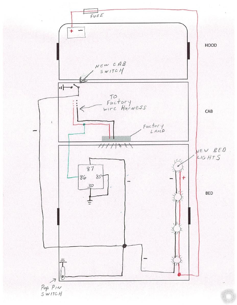
Assuming this diagram is correct I do have 2 questions.
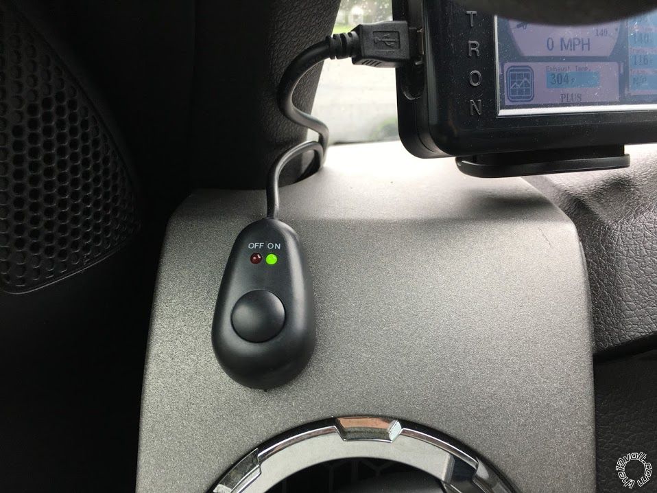
1. The style switch I plan to use in the cab has red and green indicator lights to tell whether it is on or off. (see attachment) I am pretty sure those will not work in this configuration. Am I wrong? Is there a way around that?
2. You mentioned to use an SPDT relay. I typically use a basic 4 prong relay with a 30, 85, 86, and 87 terminal. Can I just use that and attach a jumper wire connecting the 30 and 85 terminal to create what you posted above?
Posted By: the12volt
Date Posted: August 30, 2018 at 9:35 AM
The diagram is fine, but I would mount the relay under the dash instead of behind the A-Pillar, resulting in less wires to run up into the A-Pillar and easier access if need be in the future.
As far as the switch with the LEDs, I would have to see the wiring to accurately answer your question, but I would think it would be possible, however I would be concerned about it always being illuminated with the vehicle not running.
Yes, an SPST relay will work. I just keep SPDT relays in stock as most shops do for simplicity. No need to stock both. ------------- the12volt Support the12volt.com
Posted By: the12volt
Date Posted: August 30, 2018 at 9:41 AM
Without seeing the wiring for the switch, I'll assume one lead of it is ground and it relies on 12V+ being switched to illuminate the green LED when in the ON position. If this is the case, you can use it to switch 12V+ to the relay and use two diodes to isolate the dash switch and the switched lead from the bed lights. ------------- the12volt Support the12volt.com
Posted By: dieselmike
Date Posted: August 30, 2018 at 11:09 AM
My switch will be similar to the one in this article:
Wiring an illuminated toggle switch
Note the sentence: Note most switches will not illuminate if they are on the 'ground' side of the accessory.
For a toggle switch like this that opens and closes the circuit between the #1 (PWR) terminal & the #2 (ACC) terminal my application would have me connect #1 to a ground, # 2 to my Negative pigtail. That would leave #3 unused. The switch would work in terms of turning on and off my bed lights. But the illuminated light on the switch would not.
I think you mean this. Tell me if this is correct. If I have this right it will also solve your concern of having the little indicator light on all the time when truck is off.
Posted By: the12volt
Date Posted: August 30, 2018 at 11:20 AM
That'll work. ------------- the12volt Support the12volt.com
Posted By: dieselmike
Date Posted: August 30, 2018 at 12:48 PM
Thanks again, the12volt. I'm going to try and find some time to hammer this out this weekend. Will post a follow up next week with some pictures after it's complete.
I am also going to be installing Aux backup lights. I want to do it at the same time so I can tuck the entire wire run in the same protective loom. But I am okay with that wiring. Keeping that one very simple. Just a switch and a backup light trigger. Nice and easy peasy.
Posted By: the12volt
Date Posted: August 30, 2018 at 12:51 PM
You're welcome. I look forward to seeing them. ------------- the12volt Support the12volt.com
Posted By: dieselmike
Date Posted: September 04, 2018 at 7:37 AM
Well, a wrench was thrown into the plan right out of the gates. That "Pop-Pin" switch I planned to install won't work on my truck. There is no flat mating surface where it can make contact. So the whole idea that I had to wire this to cut power on the ground lead is tossed out the window. So instead of the pop pin, I will simply install a very basic on/off switch in the back of the bed. But I still plan on the other two triggers as well (a Dash Switch & tapping into the light above the rear window).
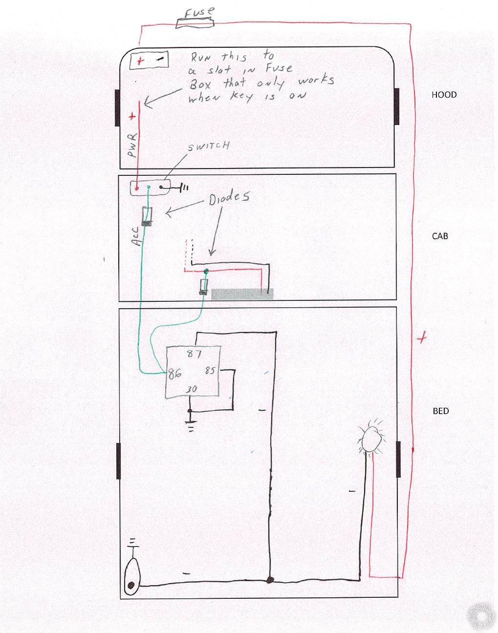
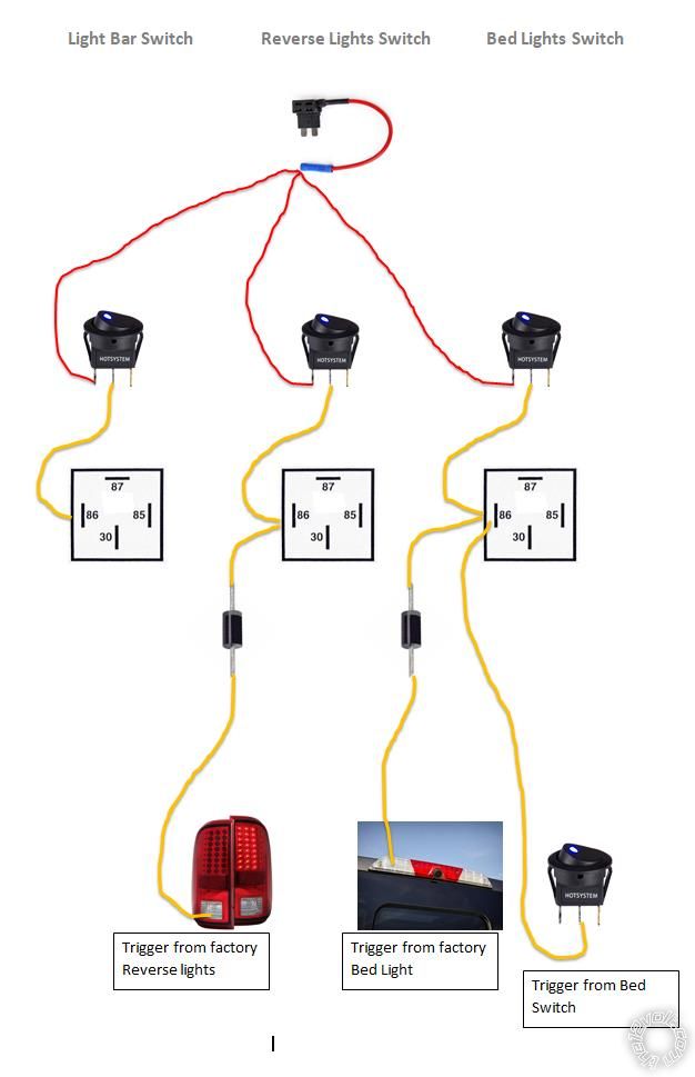
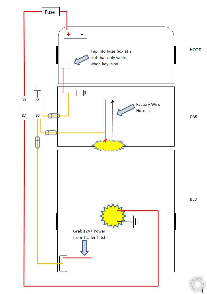
So here is Plan B which involves all 3 triggers to cut power from the hot side:

A few Notes about the picture:
1. The Dash switch has red and green indicator lights to represent On/Off. Which is why I am tapping into the fuse slot that only works with key on.
2. Tailgate switch will be a basic On/Off toggle switch with no indicator light, which is why no ground.
3. Do I need any more Diodes on the other triggers, or is the one on the trigger coming from factory light sufficient? (Is that one even necessary?)
4. Lastly, I will take any suggestions if you have a completely different way of setting this up.
Posted By: the12volt
Date Posted: September 04, 2018 at 7:54 AM
Diagram looks fine, but are you sure you have a constant 12V+ lead in the trailer wiring? I'm thinking you'll have to run one from up front.
The diode on the factory bed lights lead is to prevent those lights from coming on when either of the other two switches are on. ------------- the12volt Support the12volt.com
Posted By: dieselmike
Date Posted: September 04, 2018 at 8:11 AM
the12volt wrote:
Diagram looks fine, but are you sure you have a constant 12V+ lead in the trailer wiring? I'm thinking you'll have to run one from up front.
Yup. I considered this. I am hoping I find one (a constant 12V+ lead). If not, I guess I'll have no option but to run another. Which is a shame, because I already built two very neat wire loom runs going along the chassis. One for this project, and one for the Aux reverse lights. If I planned better, I would have had another red wire in this loom.
the12volt wrote:
The diode on the factory bed lights lead is to prevent those lights from coming on when either of the other two switches are on.
Yes. That is my understanding, which is why I was quite confident it was needed on the lead in my picture. But if I don't have one on the lead to the dash switch, will it interfere with my little indicator lights on the switch when one of the other 2 triggers are activated?
Posted By: the12volt
Date Posted: September 04, 2018 at 9:24 AM
I can't tell you if it will interfere or not with the dash switch, but it wouldn't be a bad idea to add one. If it does light up with 12V+ just on the output side of the dash switch, you could use it as an indicator if you forgot that you left the rear switch on. ------------- the12volt Support the12volt.com
Posted By: Ween
Date Posted: September 04, 2018 at 5:21 PM
In the battery junction box (fuse box under the hood), there should be a relay labeled as trailer tow, battery charge. This is the +12V
that is available at the 7 pin trailer connector, orange wire. However it is controlled by the ignition switch by said relay. If the relay is removed,
and a jumper wire placed between terminals 30 and 87, unswitched power will be available on the wire. Add a fuse inline for the added circuitry (lights)
of course.
Posted By: dieselmike
Date Posted: September 05, 2018 at 7:40 AM
Ween, Thanks for the contribution to the thread. It's so funny you mentioned this. After the12volt replied to me questioning power at the hitch, I starting digging the depths of the internet. Sure enough, modern day Ford Trucks only supply 12V+ at the 7 pin hitch connection when truck is on. I stumbled across your exact suggestion on one of the Ford Truck Forums. This is a great solution and one I am certainly going to implement. So glad I don't have to make another run to to front. It's getting a little tight routing all these wire looms along the frame rail and into the engine bay.
Onto my next question... So far I have only discussed wiring up 3 triggers for my bed lights. But need a little advice regarding the dash switches I will be installing. There will be a total of THREE after market dash switch in my cab:
1. For a grill mounted light bar (already installed and operational)
2. For the reverse lights
3. For the Bed Lights we've been discussing
My question is this: Can I power up all three switches jumping from the same fuse tap? Or does each switch need it's own fuse tap? Keep in mind, the power coming from the fuse tap is only to power the switch(es) as all three application are run through a relay. None of these dash switches will be handling the loads on the lights. Here's a quick and dirty diagram of what I am thinking. For clarity and not confuse the picture, I am not showing the grounds. But keep in mind all of these switches have indicator lights so will require a ground. I am aware of that. I am also not labeling the 30, 87 or 85 Posts on the relay. I understand that each relay will have a dedicated fused line direct from a 12V+ source to 30. 87 will run to said new Aux Lights. And 85's gets grounded.
Posted By: the12volt
Date Posted: September 05, 2018 at 9:54 AM
Yes, that will work. ------------- the12volt Support the12volt.com
Posted By: dieselmike
Date Posted: September 05, 2018 at 10:02 AM
Perfect. Thank you sir. I'm thinking a 3 or 5 amp fuse on the "add a circuit" fuse tap. That sound good? Also, I am going to run an Ampere test on each of these new applications to decide what fuse to use for each coming from the power source. Then I'll run that by you for approval. I know this has taken some turns and modification from when I started this thread. So once again. Really appreciate you answering all this and sticking with me. Really helping me through this install.
Posted By: the12volt
Date Posted: September 05, 2018 at 10:41 AM
A 3 or 5 amp fuse will be fine for your switches.
You shouldn't need to run a test if you already have the specs for the devices you are powering. Just remember to never use a larger fuse than the current rating of the wire you used.
------------- the12volt Support the12volt.com
Posted By: dieselmike
Date Posted: September 05, 2018 at 11:27 AM
Well, the Light bar up front is 120 Watts according to the specs. So that's pulling about 10 amps at 12 Volts, or about 8.5 amps at 14 volts.
Reverse lights 96 Watts - So 8 ish Amps
Bed lights are so low the Specs don't even mention it. But when I asked around I was told they don't even pull 1 full amp.
I used mostly 14 & 16 Gauge wire. Some 18 on the triggers and switches. Max run length anywhere is maybe 25 feet. Though that is estimating very much on the high side. So I was thinking a 10 or 15 on the higher powered circuits and a 7.5 or less on the Bed lights.
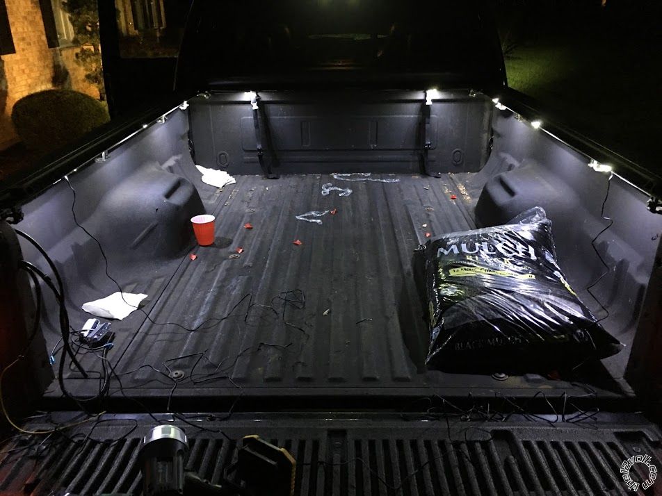
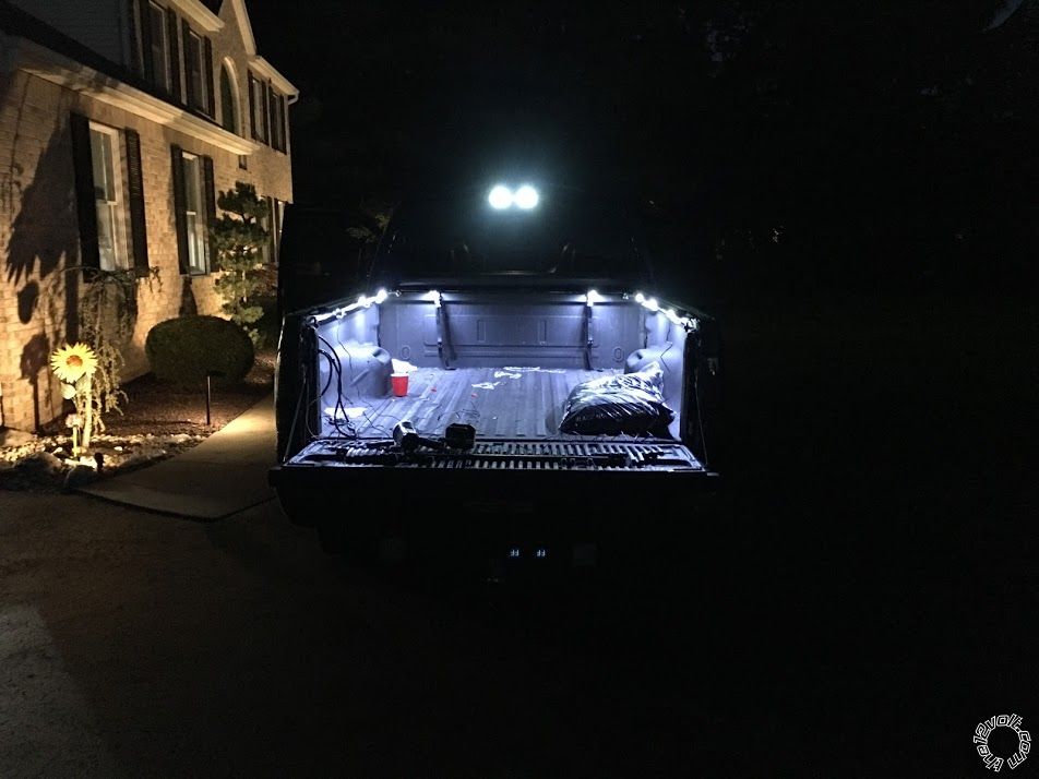
By the way. Here's a pic of the bed lights last night.
Posted By: the12volt
Date Posted: September 05, 2018 at 11:51 AM
15 and 7.5 will be fine. ------------- the12volt Support the12volt.com
Posted By: dieselmike
Date Posted: September 12, 2018 at 8:47 AM
Update:
Wow. This turned out to be some project. On paper it looks great. Once you start running the wires, spicing, crimping, shrink wrapping, protecting everything in wire loom, zip tying, etc, it gets very tedious. But for the most part I am done.
Observations regarding diodes:
Originally I installed the bed lights with only a diode on the trigger line coming from the factory rear window light as shown below:
 But the problem with that was:
That rear window light goes ON under under numerous scenarios even when the truck is completely off, key out of ignition. For example, if I lock or unlock the truck using my key FOB, that light goes on. If I walk up to the truck and open the door, that light goes on, etc. So this is what I noticed. I would open up the drivers door, lights would turn on. Good so far. But if I turned on my dash switch before the delay would turn off the lights, the power would now run BACKWARDS through that switch, into the fuse box (where I tapped in) and activate the entire fuse box. (Follow on diagram above). This caused all kinds of scary things, such as: I would hear the fuel pump under the hood engage, the engine blower motor would go on, the Glow Plug cycle would start (diesel engine).
Said another way; If I turned on my new dash switch while the factory light was on, the truck "thought" I stuck the key in the ignition.
Hopefully that makes sense.
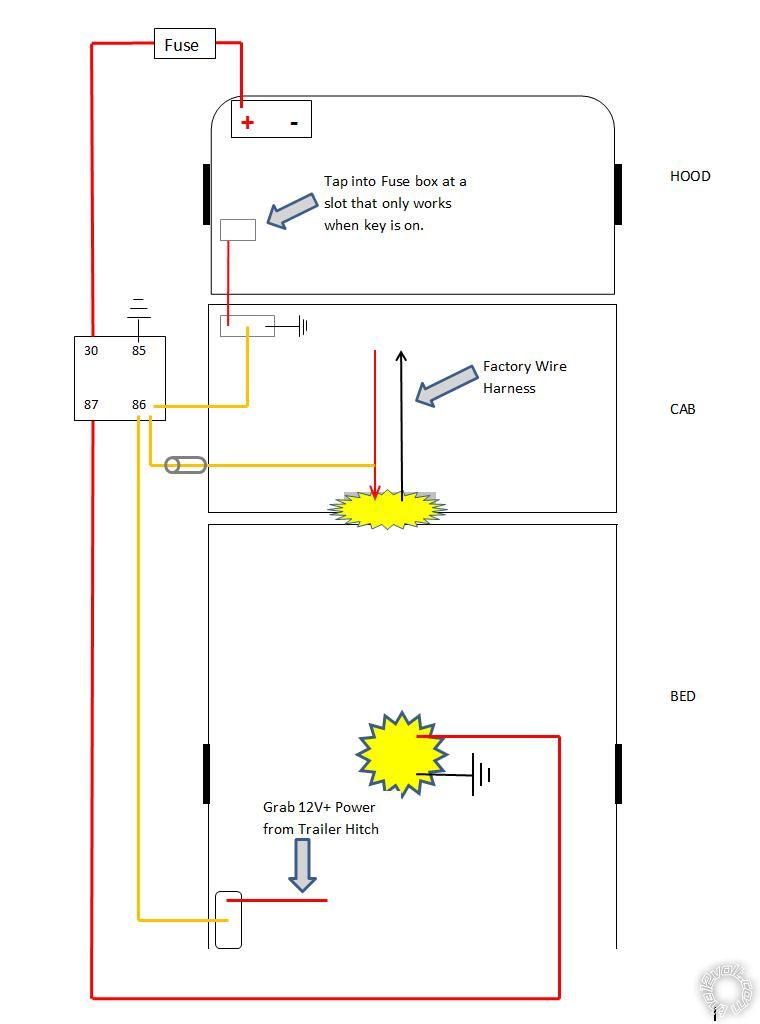
The Solution:
Install a diode on the yellow trigger wire between the relay and the dash switch. For good measure I also installed one on the yellow wire going to the bed switch. I considered installing one on the wire coming from the fuse box to the switch also, to completely control which direction electricity can flow. But I thought this was not necessary as I already blocked flow in that direction from all points of entry. Sure enough I tested it with the news diodes in place and all works well now. So this is what it currently looks like:
 Now regarding getting power to my bed switch:
 (God bless ya if you're still with me - LOL)
We discussed last week that I wanted to tap into my 12V+ at the 7 pin hitch connection in the rear to power my bed switch. But that there was the possibility that the connection wasn't live with the key off. Which ended up being the case. I took Ween's suggestions below and made that live all the time:
Ween] wrote:
In the battery junction box (fuse box under the hood), there should be a relay labeled as trailer tow, battery charge. This is the +12V
that is available at the 7 pin trailer connector, orange wire. However it is controlled by the ignition switch by said relay. If the relay is removed,
and a jumper wire placed between terminals 30 and 87, unswitched power will be available on the wire. Add a fuse inline for the added circuitry (lights)
of course.
So now I can walk up to the truck at night; key out, ignition off. Open the tailgate, turn on switch I mounted just to the side of the bed and turn the bed lights on. (Yes I am aware I can drain the battery this way if I forget to turn em off).
Now that orange wire I tapped into at the 7 pin is already protected by a factory fuse in the fuse box. So I don't believe it is necessary to add a fuse where I tapped into it. Do we agree on this? Remember, that tap is not even powering the bed lights. It's only powering my bed switch which in turn activates the relay. The bed lights themselves are of course on a protected circuit coming straight off the battery (again refer to diagram above).
OK. Long post. Hope everything I discussed here is clear. This has certainly been a learning experience for me.
|