How To Transform An Intermittent Signal To A Constant One?
Printed From: the12volt.com
Forum Name: Lights, Neon, LEDs, HIDs
Forum Discription: Under Car Lighting, Strobe Lights, Fog Lights, Headlights, HIDs, DRL, Tail Lights, Brake Lights, Dashboard Lights, WigWag, etc.
URL: https://www.the12volt.com/installbay/forum_posts.asp?tid=147024
Printed Date: April 30, 2026 at 4:55 PM
Topic: How To Transform An Intermittent Signal To A Constant One?
Posted By: saitch0
Subject: How To Transform An Intermittent Signal To A Constant One?
Date Posted: September 05, 2021 at 7:46 PM
Hi guys,
I want to use the intermittent signal of my blinkers and turn it into a constant signal to power cornering lights. I poked around and installing a capacitor is one of the solution. The draw of the cornering lights is about 1 amp.
I am pretty new to electronics but eager to learn. If I understand right I install a capacitor to the red wire that power the light and it will charge itself from the intermittent signal of the blinkers and it will be able to power the cornering lights when there is no power and making the signal constant. If I use capacitor that is too small it wont be able to hold enough power and there will still be an interruption in the signal. If I pick a capacitor that is too big it will power the circuit too long after the blinker signal is stopped. What size capacitor do you suggest so I can buy the correct set on amazon.
Vehicle is a Suzuki Carry if it matters.
Thanks
Replies:
Posted By: Ween
Date Posted: September 05, 2021 at 8:49 PM
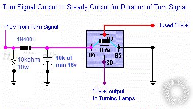
This... https://www.the12volt.com/relays/relaydiagram22.html
With using the capacitor across the relay coil, the load current (cornering light) doesn't effect the 'on' time. The capacitor keeps the relay coil energized between flashes, and slightly after the turn signal is cancelled.
Posted By: i am an idiot
Date Posted: September 05, 2021 at 9:30 PM
Posted By: saitch0
Date Posted: September 06, 2021 at 9:05 AM
Ok lets see if I understand everything.
The pink wire out of 86 represent the pulsed signal coming out of the flasher relay.
I need to connect one side of a 10k resistor and one side a 10kuf capacitor to that line. Then that line continues to my LED light.
I then need to link together the other side of the capacitor and resistor and ground them.
Resistor
Capacitor:
Are those the needed components?
Anyone can explain to me why I need to ground the capacitor and resistor and why a resistor is needed?
Thanks
Posted By: Ween
Date Posted: September 06, 2021 at 5:06 PM
The resistor (10k ohms) isn't needed. The capacitor needs to be grounded so as to be able power the relay during the time when there isn't power being supplied through the diode. The diode is needed to isolate the power coming from the flasher. If it wasn't there, the capacitor would discharge into the front turn signal circuit.
Posted By: saitch0
Date Posted: September 07, 2021 at 1:26 PM
Thanks Ween for the explanation. After more research I plan to go with those components:
Capacitor: Radial Electrolytic Capacitor 25V 10000UF 105C
Diode: HUABAN 1N5400 Rectifier Diode 3A 50V
Are those the right ones for my project?
Posted By: Ween
Date Posted: September 07, 2021 at 9:23 PM
A 3A diode is a bit overkill for the project. 1N400* series diodes would be fine, !N4001 or !N4002.
Posted By: pfix
Date Posted: October 31, 2021 at 11:26 AM
If u need a resistor to keep the blink-rate it may be solved like this
( modified version of : https://www.the12volt.com/relays/relaydiagram22.html )
If u got a LED blinker relay u don't need the 10k resistor
Posted By: pfix
Date Posted: October 31, 2021 at 12:09 PM
Here is what I used on a CBR1000 with "aftermarked" LED sequential rear turn-signals :
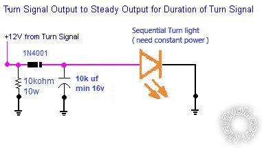
I plan to install LED's in the front turns also, then the 10k resistor will not be needed anymore :)
|