Hello all,
It has taken me a while to to get here but here goes. Hope this works as I often have mixed results posting on forums...
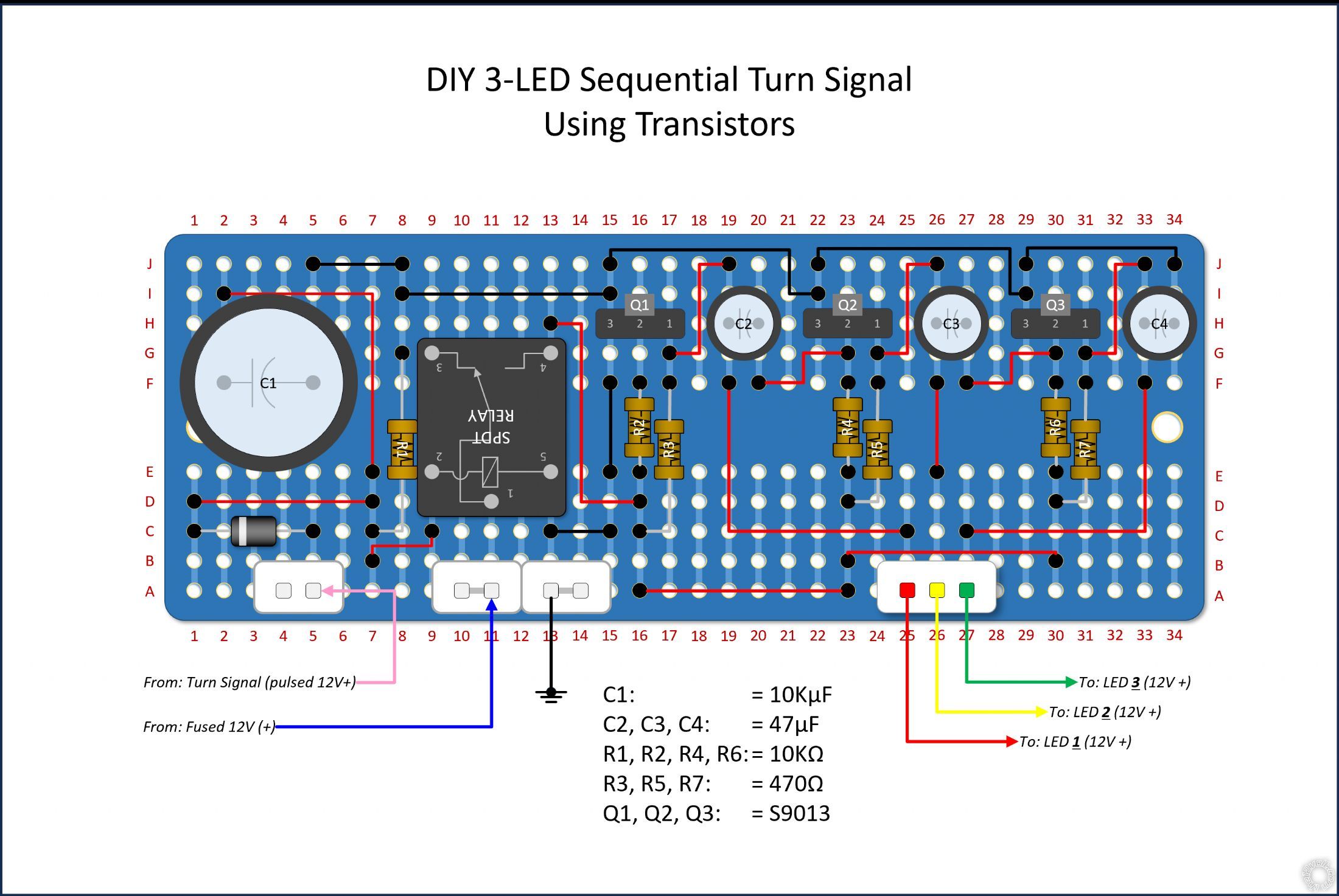
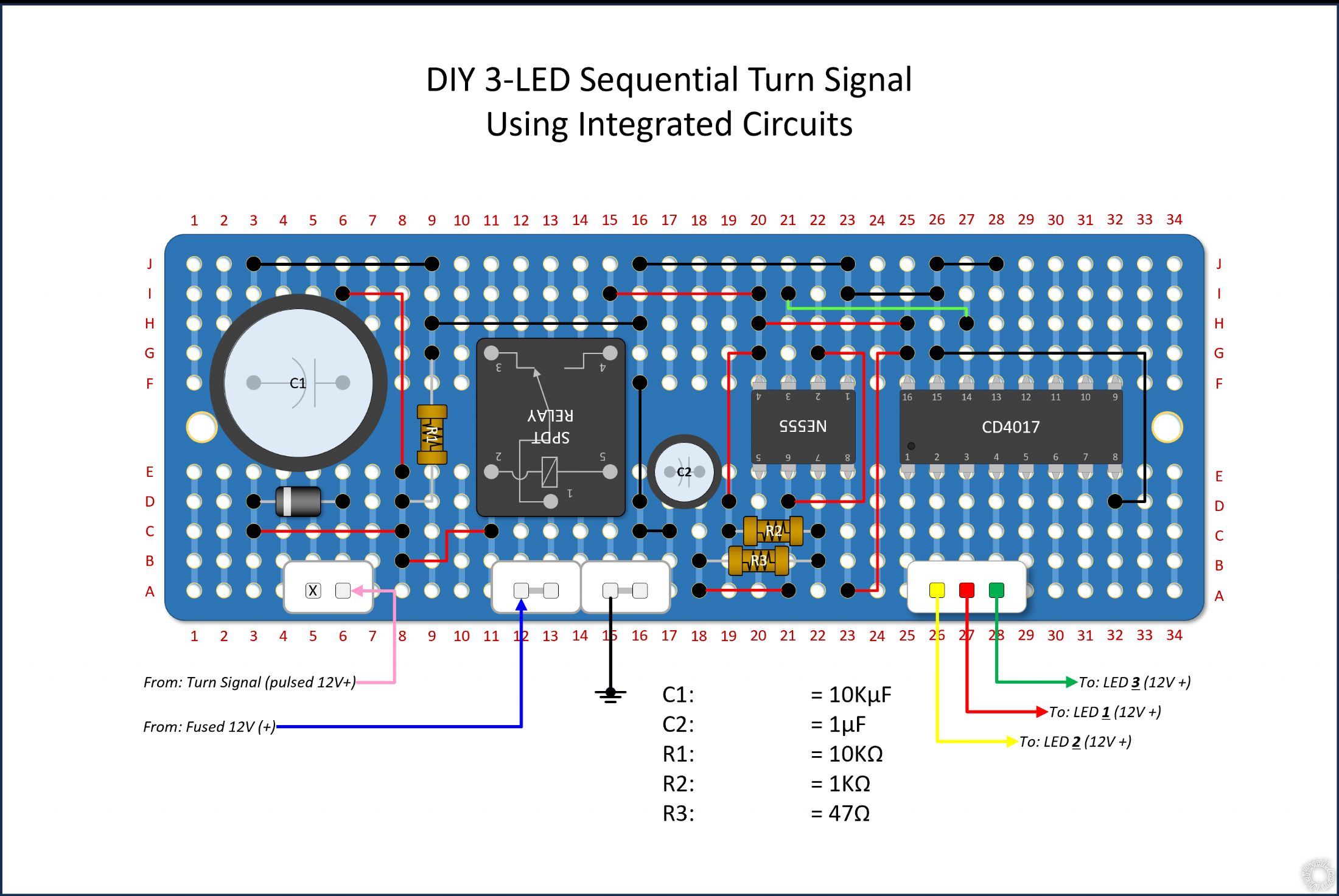
I have installed a set of 3 LED turn signals in both front fenders of my Jeep. Initally I was using a cheap aftermaket sequencer to run them but it failed after about 6 months (as always you get what you pay for). In researching a fix I came up with two posibilies; one 555/4017 IC based, one Transistor based. BTW - I used a relay diagram from here to even out the pulsed signal input.
NOTE: The pics I've attached are not curcuit diagrams, but pcb layouts. Experience has tought me they are
NOT the same thing! I'm working inside a 3"x 4" project box that already has a mounting place (with wiring run to it), so space is limited to that. Two of the PCB's I've depcited fit nicely (1 for Lt, 1 for Rt). They are not to scale but the relationship between components is reasonably accurate. In case you're interested, these, like almost allmost all my wire diagrams, were done in PowerPoint. It's a kind of hobby. I see them as puzzles. I even did my lawn tractor once...
Basically I'd like some input on whether either or both will work (with or w/o modifications?) I'm not into the math and I had some difficuly finding different diagrams that used the same components (for confirmation). Any direction on specs, P/N's, etc., would be greatly appreciated!
Once I have my final board design l'll post the full lighting diagram.
Thx
-------------
Joel
A plug-in breadboard version of the IC based plan didn't work... :(
The lights barely flickerd. More so #2 than the others. Not sure if it's the proponderance of inherently loose connections or I just have it wrong.
Any guidance?
Joel
-------------
Joel
Made some adjutments on the breadboard - got Smoke! The 4017 chip overheated between pins 16 & 15 (B+ & Gnd). Are there different voltage ratings for these chips?
-------------
Joel
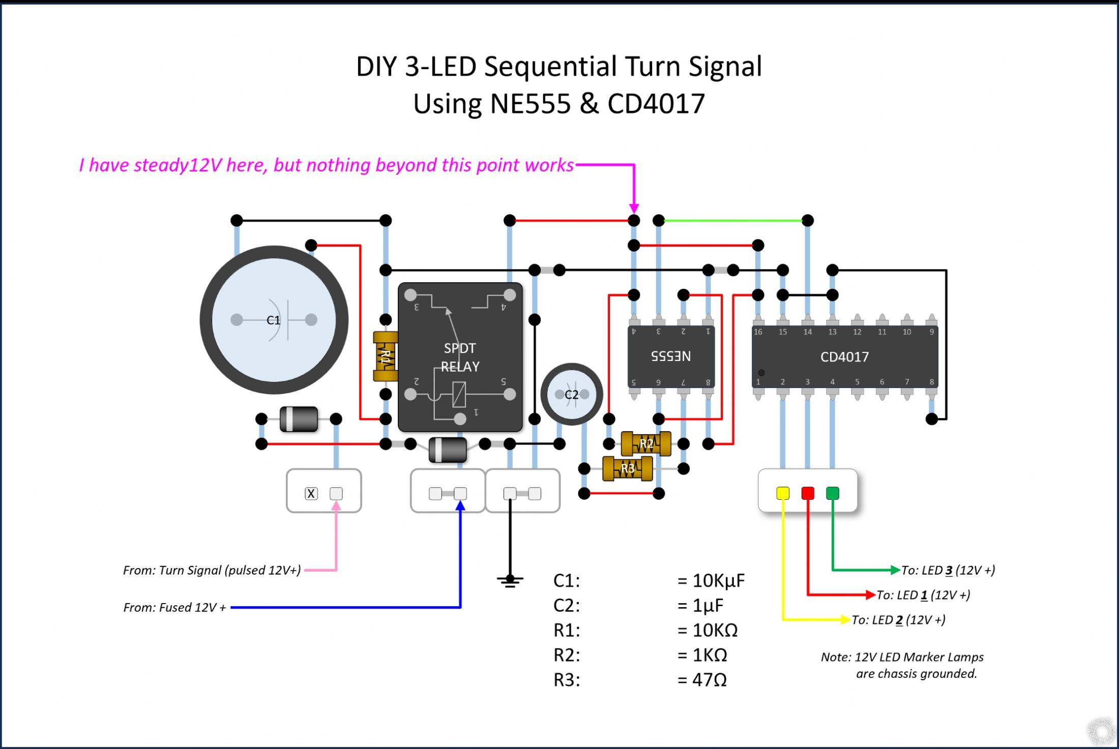
OK, last ask. The lack of a even a single conmment is very discouraging...
I cleaned up my diagram and removed the PCB graphic. Hopefully is is easier to read. Ive studied 555/4017 diagrams till my eyes are crossed. This
SHOULD work but it doesn't!
BTW - Both chips are rated up to 15V
Thx,
-------------
Joel