Transistors to switch leds on/off
Printed From: the12volt.com
Forum Name: Lights, Neon, LEDs, HIDs
Forum Discription: Under Car Lighting, Strobe Lights, Fog Lights, Headlights, HIDs, DRL, Tail Lights, Brake Lights, Dashboard Lights, WigWag, etc.
URL: https://www.the12volt.com/installbay/forum_posts.asp?tid=72491
Printed Date: March 14, 2026 at 3:47 PM
Topic: Transistors to switch leds on/off
Posted By: recognition
Subject: Transistors to switch leds on/off
Date Posted: February 09, 2006 at 7:09 AM
Hi, I'm new! Right, I need to wire up a blue led and red led. They need to switch from red to blue when 12v signal is applied. I have used relays before but found them to noisy (I want a silent operation) I have a basic understanding of transistors but could do with some guidance. Or alternatively, I know I can switch from blue -> red without a relay or transistor because the red led has less resistance then the blue, but can I make it work the other way round? Cheers!
Replies:
Posted By: firstrax
Date Posted: February 09, 2006 at 7:37 AM
Posted By: coppellstereo
Date Posted: February 09, 2006 at 9:38 PM
what is PNP and NPN ? -------------
Posted By: firstrax
Date Posted: February 09, 2006 at 9:45 PM
coppellstereo wrote:
what is PNP and NPN ?
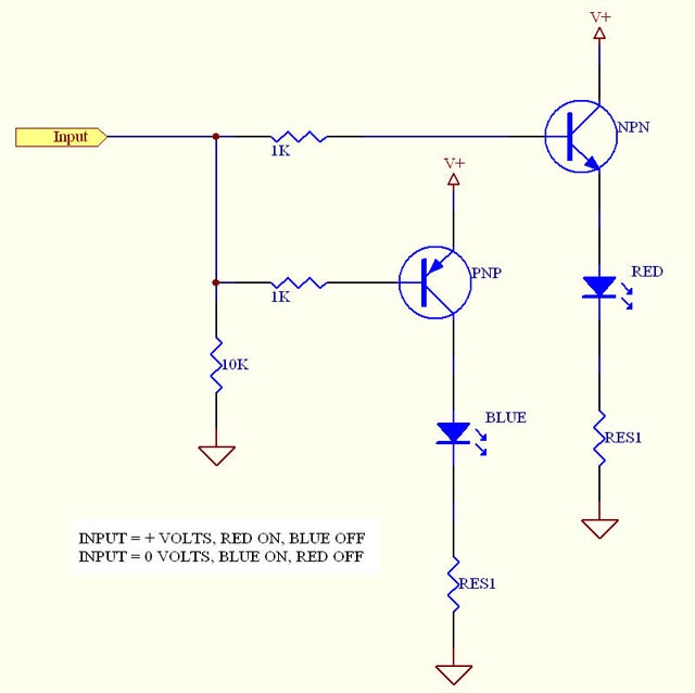
Basically, PNP, 0 or -volts on the base switches the transistor on. NPN, + volts on the base switches it on.
Posted By: coppellstereo
Date Posted: February 09, 2006 at 9:50 PM
I think I understand. I'm new to reading these schematics.
-------------
Posted By: firstrax
Date Posted: February 09, 2006 at 10:07 PM
Its like relays. The first few times we touch them they seem strange and complex. But after wiring up a few they become just another tool.
Posted By: recognition
Date Posted: February 10, 2006 at 3:59 AM
Thanks for the diagram, but I think that works in the opposite way to what I want. When 0v from the input, red should be on and blue off. When theres 12v from the input, it should be blue on and red off. Should i just swap the PNP and NPN transistors around? Also, I've been trying to make this but with no luck. would I need NPN transistors for this schmatic? Thanks for your help! 
Posted By: firstrax
Date Posted: February 10, 2006 at 8:15 AM
Try this. 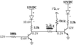
Probobly not enough current to the bases to forward the transistors. Try a pull up on the base of the second transistor. Might also want to lower the resistance of the base resistors to get more current through the base. You can go all the way down to the hundreds without damage. Yes those should be PNP. Recommend 2N3904. Also, if the input to the base of the first transistor floats when not connected to 12v you will need put a pull down resistor on it. If you float a base its anyones guess what state of saturation it will be in.
Posted By: firstrax
Date Posted: February 10, 2006 at 8:17 AM
recognition wrote:
Thanks for the diagram, but I think that works in the opposite way to what I want. When 0v from the input, red should be on and blue off. When theres 12v from the input, it should be blue on and red off. Should i just swap the PNP and NPN transistors around?
Your right, opposite. Swap the leds, not the transistors.
Posted By: firstrax
Date Posted: February 10, 2006 at 8:20 AM
firstrax wrote:
Those should be PNP. Recommend 2N3904.
I meant to say NPN. 10 times fast, npn,npn,npn........................
Posted By: recognition
Date Posted: February 10, 2006 at 11:27 AM
Cool! thanks for your help! Been using relays but I want a much smaller, quieter set-up. This should get me started well! Cheers!
Posted By: AZ-ss
Date Posted: February 20, 2006 at 6:11 PM
I have a question about using transistors instead of relays. My example is- I have a switching (positive or negative) source for a circuit that is aprox. 3 volts and I would like to control a positive source of 12+ volts. I think I understand that the Collector and Emitter would bear the 12volt end of the circuit and the Base would be the 3 volt switcher. (correct?) Now, Should the base be opposite polarity of the Collec. and emitter? And if the base receives a variance of voltage does it affect the volatge being passed from collector and emitter? (such as a dimmer circuit) Thanks!
Posted By: ff-mike
Date Posted: February 21, 2006 at 4:05 PM
Basically correct. Easiest method would be an NPN transistor:
Emitter- ground
Collector- ground lead from device
Base- 3 volt switching signal-> recommened to use a resistor
|