Hello,
I am currently using an FM modulator to transmit the audio from my Pioneer Inno to the factory stereo in an '02 Eclipse. I wanted to add an iPod through the FM mod as cheaply as possible so I bought a Belkin audio adapter and used spare parts to lying around to build my own audio switching device. I have attached a crude wiring diagram to show what I did with the relays.
Unfortunately it's not working.. it seems as though there's a channel missing from the audio no matter which source I have selected. Is it because I used 3-conductor stereo jacks for the audio switching? I think I've seen 5-conductor jacks as well but obviously that would make this needlessly complex and add extra relays, etc. Any thoughts?
Thanks
-Mike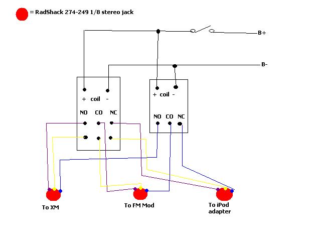
Looking at that diagram it looks like your feeding one source into another, keep it simple use the 2 fm mods on different frequencies and switch them on as you use them. Me I would have integrated the Pioneer into the car bypassing the factory system or replacing and bought an iPod adaptor to suit the head unit.
-------------
WOW Sight and Sound
Maroochydore
Nothing is impossible!
Do it right the first time or don't do it at all.
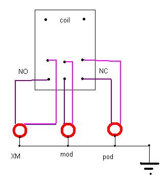
Additionally, there is no need to switch the commons (the audio ground). They can remain always connected, AND remain connected to each other - there is no reason to isolate them.
Here is how I would do it...
 :::::::EDIT:::::::
I am looking at my diagram, and yours again, and it seems the only thing I did is remove the relay isolation of the grounds. This leads me to believe that you have a solder bridge somewhere... Your implementation is correct. Something is shorted out. Check your connections again, but leave the common isolation and switching out... I would start by checking for continuity between the signal commons on the DPDT relay and ground. If it is with BOTH sources, it has to be there. It also cannot be on the SPDT, as I am assuming you are using THAT one for the commons.
-------------
It all reminds me of something that Molière once said to Guy de Maupassant at a café in Vienna: "That's nice. You should write it down."