Does anyone know the pinout for the 4 wire aux port on a 2008 ford superduty? No one seems to make any type of inline harnes and I want the install of a external xm sat reciever look clean. (no wires pluged into the external aux jack)
Thanks
Yes and Yes, but its an input... im assuming the 4 wires are as follows left +, - and right +,-
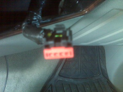
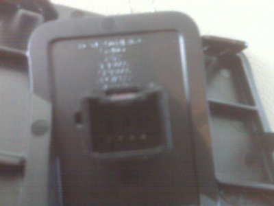
Here are some pics
I should have been a little more clear. Is there an 1/8 inch input jack that the harness plugs into?
If it does, go to Radio Shack and purchase an 1/8 inch stereo male to 1/8 inch stereo male adapter. They are a common item for the rocket scientists at any of their locations. Plug one end into the jack of the vehicle. now using your ohm meter touch and hold one lead to the tip of the other end of the cable. Now touch the other meter lead to the 4 wires on the back of the plug. (one wire at a time of course) When you find the wire that is connected to that. That would be the right signal positive wire. now move the lead to the piece of metal between the 2 black rings of the plug. Now meter the remaining 3 wires. The one that is common with this terminal is going to be your left positive signal wire. The ground connection of the plug is the metal piece between the base of the connector and the first black ring. Hold meter lead to this and test the 2 remaining wires. This is the ground or shield connection.