have i blown my amplifier?
Printed From: the12volt.com
Forum Name: Car Audio
Forum Discription: Car Stereos, Amplifiers, Crossovers, Processors, Speakers, Subwoofers, etc.
URL: https://www.the12volt.com/installbay/forum_posts.asp?tid=108190
Printed Date: May 01, 2026 at 5:30 PM
Topic: have i blown my amplifier?
Posted By: ncchance
Subject: have i blown my amplifier?
Date Posted: October 16, 2008 at 8:57 AM
This is about as stupid of a question as anyone would hope to come across, but I feel obliged to ask it anyway. I have an Orion HCCA 225 G4 amplifier. Extremely long story short....the power and ground connections got mixed up. After this issue literally came to light it was corrected, but the amp doesn't seem to turn on anymore. Is the amp more than likely toast? Thanks.
Replies:
Posted By: i am an idiot
Date Posted: October 16, 2008 at 9:16 AM
If the amp was properly fused, it should have taken the fuse out. Verify with a volt meter that the amp is getting power on the red wire and the blue wire. If it is getting power to those 2 wires and it is not coming on, you have a burnt trace on the board. It should be an easy fix. There are diodes in the amp to protect it from this exact thing. Fused properly they protect it. Improper fusing will take out a trace on the circuit board.
Posted By: ncchance
Date Posted: October 16, 2008 at 12:25 PM
I am an idiot, thank you very much! LMAO! This afternoon I'll check everything out with a voltmeter. This just happened last night so I haven't had the time to go ahead and get some readings. I just wanted to hit the ground running when I check it out after work. The amp is connected to the battery through a 30 amp fuse block and it also has (2) 30 amp onboard fuses. I did give those a look, but they didn't show any signs of failure (success). The plug got pulled out when I had to grab something out from inside of the spare tire well. (obviously a result of momentary laziness) I plugged it back in and heard a few crackles, but I figured it was just a few compenents getting energized. (haha?) I turned the stereo on and nothing from the subs, I went to check it out and realized the plug was upside down. Agh! Flipped it, plugged it in, hit the stereo and....nothing. I'm only putting that out there in case any of it had something of relevance to it. If none of my story changes anything, please disregard my response, accept my appreciation, and believe me when I say I am the real idiot here. lol ------------- "I've only gotten this far because I'm known for making every project 10x more difficult than it ever needed to be."
Posted By: bigjohnny
Date Posted: October 16, 2008 at 6:29 PM
maybe you blew a fuse in the car itself?
Posted By: i am an idiot
Date Posted: October 16, 2008 at 6:46 PM
Yes, as Johnny suggested, not a fuse in the car itself but the single 30 amp fuse you have near the battery is probably blown.
Posted By: ncchance
Date Posted: October 17, 2008 at 2:35 PM
I've checked it with the voltmeter and both wires are sending 12.26 volts to the amp with the ignition on accessory. I did replace the on-board fuses, but that didn't fix the problem. What's got me even more boggled is that I believe my subs may be blown in addition to the amplifier. They are very stiff and when hooked up to another working amplifier they have very low output. However, there is no scratching or anything. If it is a trace that is burnt out and you are still up to responding, where can I find more info. on fixing the amp? I sure could stand to save some money right now. Thanks again! ------------- "I've only gotten this far because I'm known for making every project 10x more difficult than it ever needed to be."
Posted By: i am an idiot
Date Posted: October 17, 2008 at 3:38 PM
When you checked voltages, did you have the negative lead of the meter grounded to the ground wire at the ground input terminal of the amplifier? Not at the end of the wire where it is attached to the car but at the terminal ON the amplifier.
Posted By: dragon51
Date Posted: October 17, 2008 at 5:02 PM
Check your RCA cables too, I froze a sub and killed the amp replaced the sub and the amp still did not work, after everthing else was check, we tested the RCA cables and they were bad however they looked fine. It was a weird thing.
Posted By: ncchance
Date Posted: October 17, 2008 at 10:41 PM
Actually, the first time I checked it I used the base of the trunk latch. I just ran out and tested the amp using the terminal on the amp. I got 12.62 at the Power and .684 at the remote. I tested the positive and negative jackets on the RCA. The positive was giving me 2.015 and the negative gave me nothing. For comparison I tested the RCAs going to amp powering the speakers in my rear deck. They didn't give me any readings at all. Let me also add that the car was not turned on and the key was not in the ignition. What does this mean? How can the amp be drawing power when I have an accessory relay sending the power for the remote-on? Recently, I had an issue with my head unit where it wouldn't stop sucking power no matter what I did. Unless I disconnected the power harness of course. It would get absolutely hotter'n hell and drain my battery. As it turned out the internal amp chip was scorched. I took the amp chip out of the unit since it wasn't the source of power for my speakers. Ever since I took it out and isolated the leads I haven't had any problems. Until now. Is it possible that when the Power and Ground wires were mixed up the amp used my speakers as a ground and fried everything in the path? That may sound like shear brilliance (sarcasm), but hey - what can I say? I've relied on luck this far...it was bound to go from bad to catastrophic...retardation. lol. I love me. ------------- "I've only gotten this far because I'm known for making every project 10x more difficult than it ever needed to be."
Posted By: ncchance
Date Posted: October 17, 2008 at 10:52 PM
Dragon. That was pretty wierd. How can an RCA freeze a sub? Must have been some seriously high voltage shooting from that phuker or something. I would have thought the amplifier would just stop receiving power/information from the RCAs when they go bad. Obviously, I don't know much of anything pertaining to this maddness. I'm going to go sell my system as a bad joke and pay for installs from now on. ------------- "I've only gotten this far because I'm known for making every project 10x more difficult than it ever needed to be."
Posted By: i am an idiot
Date Posted: October 18, 2008 at 12:46 AM
You need to turn the key and the radio on and check voltage again. Black lead on ground terminal of amp. Red lead to power and then to remote. If there is 12 volts on both of these wires and the amp is not on, it has a problem. Depending on what kind of radio you have, some decks get amp turn on through the output IC. You took yours our. The remote wire of your deck may now be dead. If that is the case connect the amp turn on wire to the same wire that the red wire of the deck is connected to. This will turn the amp on anytime the key is on.
Posted By: dragon51
Date Posted: October 18, 2008 at 3:56 AM
I was running I fosgate he10 with a old fosgate power 500 bridged at 2 ohm when I froze the sub, when that happened it took out the amp and the RCA cables.
Posted By: haemphyst
Date Posted: October 18, 2008 at 10:42 PM
dragon51 wrote:
I was running I fosgate he10 with a old fosgate power 500 bridged at 2 ohm when I froze the sub, when that happened it took out the amp and the RCA cables.
There was something ELSE wrong. Your description of what happened can't take out RCAs. If you "froze" the sub, you were overpowering it, period. It IS possible you somehow got a DC on the RCAs or you were running the deck into clipping, but it would have to happen from the signal end, overpowering a sub WON'T take out the RCAs. ------------- It all reminds me of something that Molière once said to Guy de Maupassant at a café in Vienna: "That's nice. You should write it down."
Posted By: ncchance
Date Posted: October 19, 2008 at 12:53 PM
Well I did like you said. Apparently my Orion amplifier has become a pretty nice subwoofer anchor. lol, it keeps my subs from moving. I'm getting 12 volts at both the Power and Remote terminals without any response from the amplifier. I do feel like the remote wire from the deck is still working because my other amps are turning on. Actually,The remote wire from the deck goes to a relay and then the relay kicks my others amps on. I checked the relay for continuity and its checks out fine. Also, however fortunate it may or may not be, my subs aren't completely gone. I hooked them up to a JL amp again and this time they worked with sufficient response. I'm pretty sure they may need to be relaced, Either they're old or there is some damage to the voice coils. I really don't know what the gritty and sticking comes from when I push in on the sub... ...the way I took a blown amp from a buddy of mine, turned it over and sprayed the hell outta the voice coil with PB blaster. The sub works again! Not nearly as good as it did when it was new, but believe it or not it worked for this particular sub in this particular instance. I sure appreciate all the help and insight ya'll have provided. I'm definitely going to spread the name of THE 12VOLT.COM!!! ------------- "I've only gotten this far because I'm known for making every project 10x more difficult than it ever needed to be."
Posted By: i am an idiot
Date Posted: October 19, 2008 at 8:08 PM
When checking the voltages, did you use the ground terminal of the amp for your ground reference? If you are willing to do a little footwork, this should be a very easy repair.
Posted By: ncchance
Date Posted: October 19, 2008 at 8:31 PM
Oh yeah, I used the ground terminal at the amp like you instructed the other day. No more trunck latch testing from me. Thanks for the lesson on that by the way. I'm absolutely willing to do a little footwork. I don't even mind doing a lot. I'm no stranger to work by any stretch of the imagination. I can only assume you are referring to repairing the blown trace on the amp? I'm ready to do whatever, whenever. Good looking out! ------------- "I've only gotten this far because I'm known for making every project 10x more difficult than it ever needed to be."
Posted By: i am an idiot
Date Posted: October 19, 2008 at 9:14 PM
You need to remove the amp from the vehicle and remove the cover so you can see the inside of the amp. I do not remember which screws they used on that particular model. I think you will need either a t-15 torx driver or a 7/64th allen wrench to remove the screws on each end of the amp. You will need a 3/32nd allen wrench to remove the screw securing the RCA jack to the amp. Leave the speaker and power plugs in the car. Remove both fuses and carefully pull that end cover over the fuse holders and the 1/8 inch remote jack. After you clear those things simply raise the cover and move it toward the other end so that it clears the RCA jacks. Put the fuses back in and set your meter to the lowest ohm setting. Touch and hold one meter lead to the power terminal of the amp. Locate the transformer in the amp, it is the round thing with wires wrapped around it, there should be a couple different color wires and a couple different size wires on it. The three legged things mounted to the heat sink, held down by the silver clamps are the transistors. The ones located very near the transformer are the power supply transistors. You need to touch the other lead to the center leg of one of these transistors. You should be able to do this without touching the metal clamp. If you can not do it without touching the clamp it is pretty easy to remove, simply place a screwdriver in the slot on top of the clamp, there are 2 slots on each clamp. With the screwdriver inserted in the slot, move the screwdriver gently toward the center of the amp, once that side comes out, do the same to the other slot in that clamp. Grab the clamp and move it toward the center of the amp. The clamp goes down below the board, you have to get the lower part of it above the board so you can get it out of the way. Now touch the other meter lead to the middle leg of one of the transistors. It should read a dead short. If it reads near 0 ohms, the problem is possibly the ground trace. Now touch and hold the meter lead to the ground terminal of the amp, touch the other lead to the right leg of the same transistor. It too should read near 0 ohms. Let me know what you find out. DO NOT CONNECT THE AMP WITH THE CLAMP REMOVED. to reinstall it simply work it back under the board and push the top of the clamp (with your hands) back over the ridge of the heat sink. Make sure it is at the same level as the neighboring clamps.
Posted By: ncchance
Date Posted: October 20, 2008 at 8:28 AM
Awesome! I can't wait to give this a shot. The only problem I might have is with my meter. You mentioned setting it to the lowest Ohm setting. I have a Fluke multimeter, but I'm not sure it has that option on it. All I do is slide the selector switch and push one of four buttons. I'll run out to the car here in a little bit and grab it along with the user manual. Worst case scenario I'd have to wait until Thursday evening when I'm at my Uncle's house to get you the results. I know for fact that he has a top of the line, do everything but mow your lawn type of multimeter. I'll get back to you shortly...
-------------
"I've only gotten this far because I'm known for making every project 10x more difficult than it ever needed to be."
Posted By: i am an idiot
Date Posted: October 20, 2008 at 8:58 AM
Your fluke meter is an auto-ranging meter. Just set it to ohms
Posted By: ncchance
Date Posted: October 20, 2008 at 9:16 AM
Nice! I'll get on that after work. I should have results for you by 5:00.
-------------
"I've only gotten this far because I'm known for making every project 10x more difficult than it ever needed to be."
Posted By: ncchance
Date Posted: October 20, 2008 at 4:21 PM
Alrighty. I did everything exactly as you instructed. With the lead connected to the positive terminal of the amp and the other lead touching the middle leg of the transistor nearest to the transformer I got a reading of 0 Ohm. With the lead connected to the negative terminal on the amp and the other lead touching the right leg of the same transistor I got a reading of 0.136 Ohms. Sorry I'm a little later than anticipated...held up at work.
-------------
"I've only gotten this far because I'm known for making every project 10x more difficult than it ever needed to be."
Posted By: i am an idiot
Date Posted: October 20, 2008 at 5:45 PM
One meter lead on the center leg of the transistor and the other lead on the right leg of the transistor. This should not be a dead short. Then reverse the leads so that the one that was on center is now on right. Notice and post both of those readings.
Posted By: ncchance
Date Posted: October 20, 2008 at 9:58 PM
Red lead to center leg and black lead to the right leg = starting at about 100.0 and just keep going up to about 345.1 and turns to 0. I've done this about 10 times each and sometimes it just stays at 0. Am I messing this up or is this a dead short?
Red lead to right leg and black lead to center leg = Same thing, only sometimes its starts at negative and then goes to 0.
I don't think I'm a total idiot, but it is completely possible. If it sounds like I'm messing it up I'll just score some alligator clips tomorrow and test it again. Sorry for the delays in response. I've got a whole lot going on right now.
-------------
"I've only gotten this far because I'm known for making every project 10x more difficult than it ever needed to be."
Posted By: i am an idiot
Date Posted: October 20, 2008 at 10:09 PM
That is exactly what it is supposed to do if the power supply transistors are in working order. Put the clamp back on the transistors. There is a chip located between the power terminals and the transformer, what is the number on that chip. I am looking at ampguts, the only amp they have close is the 250G4. If the layout is not like the 225, the chip you are looking for is going to be numbered one of the following, 2 or 3 letters then the number 494 or 594 or 2 letters 3524, 3525, or 3526. Do you see such a chip? and which one is it? We are going to need to put the amp back in the car to do a little testing. leave the bottom cover off for now.
Posted By: ncchance
Date Posted: October 21, 2008 at 7:18 AM
I've actually just now received your response. I would have checked for it one more time last night, but I had a lady friend pay me a visit. I'm glad to hear that something on this amp is working correctly. Since I live pretty close to my office I'll run home during lunch and get the chip information for you. I typically take either 11:00 or 12:00 lunches, just depends on how many research subjects actually show up today. It wouldn't be until 4:30ish that I'd be able to put the amp back into the car. I hope that's cool. ------------- "I've only gotten this far because I'm known for making every project 10x more difficult than it ever needed to be."
Posted By: i am an idiot
Date Posted: October 21, 2008 at 7:24 AM
Don't hurt yourself on my account. Today tomorrow this weekend it makes ME no difference.
Posted By: ncchance
Date Posted: October 21, 2008 at 7:34 AM
I appreciate that! I'm anxious to get this amp working again and to hopefully learn a ittle bit in the process. However, like I said, I do have a lot going on. Let's just plan for the lunch thing and we'll just see where it goes from there. I try to at least give you an approximate time of when I should have any information for you. That doesn't mean I expect you to respond then or even that day. Its just sort of a force of habit picked-up from work. Thanks again!
-------------
"I've only gotten this far because I'm known for making every project 10x more difficult than it ever needed to be."
Posted By: ncchance
Date Posted: October 21, 2008 at 5:39 PM
What a suck butt day it has been. I've got the chip you are talking about. It has KIA494AP 026 printed on it. I can provide pictures if you'd like.
-------------
"I've only gotten this far because I'm known for making every project 10x more difficult than it ever needed to be."
Posted By: i am an idiot
Date Posted: October 21, 2008 at 6:19 PM
Put a 10 amp fuse in only one fuse holder of the amp. No other fuses in the amp, only 1 10 amp fuse. Remember to reinstall the transistor clamp before putting the amp back in the car. I need to know the DC voltage on a few pins of the 494. Reconnect the amp and turn the radio on, connect the black meter lead to the ground terminal of the amp. I need to know the voltage on pins 3,4,7 8,9,10,and 12. Be very careful not to touch any 2 pins at one time. 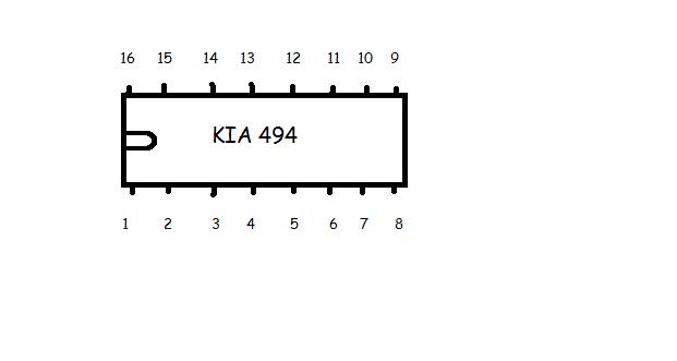
Posted By: ncchance
Date Posted: October 21, 2008 at 9:22 PM
I probably should have warned you. I get real anxious when I'm supposed to be very careful. I ended up accidentally arcing the positive and negative amp terminals resulting in a quick spit of sparks. The fuse was fine. It did leave a little brown pit in the negative terminal. I'm such a jackass...
These are the numbers I've recorded.
3 = 0
4 = 0
7 = -.001 (bounces between 0 and -.001)
8 = .062 and very slowly rising
9 = 0
10 = 0
12 = -.001 (bounces between 0 and -.001)
Here's the really odd thing. For someone unknown reason I decided to switch which side the 10 amp fuses was in. Here are the numbers I recorded with the fuse switched to the other slot:
3 = 0
4 = 0
7 = alternates between 0 and a long beep
8 = .713 and very slowly rises
9 = 0
10 = 0
12 = 1.104
-------------
"I've only gotten this far because I'm known for making every project 10x more difficult than it ever needed to be."
Posted By: i am an idiot
Date Posted: October 21, 2008 at 9:59 PM
Are you sure that the radio was turned on? With the radio turned on check voltage on the remote wire. Pin 8 and 12 should have near 12 volts on them.
Disconnect the amp and set your meter to ohms and check from the ground terminal to pin 7. It should show a dead short.
Posted By: ncchance
Date Posted: October 21, 2008 at 10:09 PM
Oh yeah, the radio was definitely turned on. It is likely I didn't have a good connection somewhere. I'll check it tomorrow morning once I get to work. I'm thinking I'll have some readings for you before or around 9. I'll probably have to run into the office for a moment. Once again, I appreciate your patience and working with me like you are. Its mighty cool of you.
-------------
"I've only gotten this far because I'm known for making every project 10x more difficult than it ever needed to be."
Posted By: ncchance
Date Posted: October 22, 2008 at 4:35 PM
One thing I know is that I need a new job...BADLY!
The pin 7 showed 0.3 ohms from the ground terminal with the amp disconnected. Something very strange that I came across (b/c I don't know a damn thing) is that when everything but the remote is disconnected from the bad amp and I touch the black lead to the ground terminal of my good amp I get 11.84 volts on pins 8 and 12 on the bad amp (using the red lead of course; I'm just trying to be as thorough as possible in explaining what I do on my end) What that mean? Also, not trying to question you in any way whatsoever, but the amp came with two 30 amp fuses in it. Would I not want to use one 30 amp fuse while running these tests? Just throwing that out there just in case. Like I said, you know what you're doing...and I don't know what I am F-ing up. I do some work with disadvantaged children until 9 tonight. I'll be able to respond to any questions you might have or be able to do anything need me to do after that.
-------------
"I've only gotten this far because I'm known for making every project 10x more difficult than it ever needed to be."
Posted By: i am an idiot
Date Posted: October 22, 2008 at 5:19 PM
With only remote connected to that amp, and your radio on, if you use the other amp's ground as a reference, you should get 12 volts on anything and everything in the Orion amp. 12 volts going in via the remote wire, the voltage goes everywhere looking for ground. It can not find ground because the amp is not grounded. 12 volts should be everywhere. The reason for the single 10 amp fuse was incase you accidentally touched pins 10 and 11 at the same time you would have turned the power supply transistors on wide open. They would last about a half of a second in this state. They would not blow 60 amps worth of fusing before they failed. How are you at soldering? Can you put your meter on ohms and verify that pin 8 and 12 are connected together. Also check from 11 to 12. Do you have an old IDE or Floppy ribbon cable that you can cut up to use one of the wires so we can make a jumper?
Posted By: ncchance
Date Posted: October 22, 2008 at 11:22 PM
That was an awesome explanation, it actually made sense to me. Thanks for looking out. I'm pretty good at soldering. I've had a lot of practice recently. Not that you asked, but in case it were to come up, I've never de-soldered before, but I can always get help with that. From what I understand there is more to it than just heating up the solder and pulling a component off a board.
Unfortunately, I'll have to let you know about the 8 to 12 and 11 to 12 readings tomorrow.
Hopefully this pic I uploaded actually shows up correctly. This is on the back of a laptop keyboard. Would that suffice to get a jumper from. I also have an old camera phone I can bust open. I really don't even mind running over to RadioShack and picking up some jumper wires tomorrow afternoon.
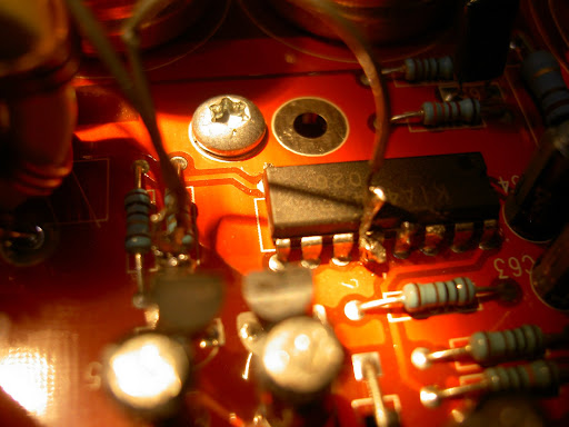
I also added a pic of the amp, I have some closer, more detailed pics. I'm just throwing it out there in case you wanted to give me a reference at any point.

 ------------- "I've only gotten this far because I'm known for making every project 10x more difficult than it ever needed to be."
Posted By: i am an idiot
Date Posted: October 23, 2008 at 6:03 AM
The ribbon cable on the laptop keyboard is not what you need for this task. If you have to buy something, buy an IDE hard drive cable. It will have 40 or 80 actual wires that you can use. A 40 conductor harness will probably be a better choice for this job. If pins 8 11 and 12 are all connected together, you need only 1 jumper. If 11 and 12 are not connected together, (you will still need only one jumper) you will need to connect the jumper to both of those pins. Cut the end off of the longest section of the ribbon cable and strip 1 of the 40 strands from the cable. Strip each end of the cable back about 1/8 of an inch. Heat up your iron and apply solder to both ends of the wire. If 8 11 and 12 are all connected together via the circuit board, it will be safer to solder to pin 8, you can get to the end of the chip and should have no chance of bridging it to pin 7. That would not be good. 8 is power and 7 is ground. Heat up pin 8 and apply some solder to the pin. Now that there is solder on each surface, place the jumper wire against pin 8 and heat both surfaces. The wire will heat up, you need to be holding it back about 6 inches. Once the solder melts on the wire and the pin, remove the heat and keep the wire in place as long as you can without burning your fingers. Once the solder has cooled, gently tug on the wire to make sure it is connected good. If 11 and 12 are not connected together, you will have to put the jumper on both of those pins. Apply solder to both of those pins, place the jumper between the 2 pins, heat, melt and remove heat, tug on wire after it has cooled. If 8 11 and 12 are common Just do 8. It is much safer. Remember only 1 10 amp fuse. Plug up the power harness only. No RCA no speaker terminals just power. Now briefly touch the other end of the jumper to the power block, notice if the light comes on, if it does come on next time leave it on for a couple seconds. If it remains on for a couple seconds and does not blow the fuse, connect the RCA and speaker connector and see if it plays. Play it at low volume only, the 10 amp fuse will not go far. If it plays at low volume we know that the power supply is OK, all we need to do now is figure out which transistor in the path between the remote terminal and the 494 is bad. Let me know what you figure out.
Posted By: ncchance
Date Posted: October 23, 2008 at 3:55 PM
Before I go buy a new IDE cable let me ask you this. Would it be possible to use a standard serial cable? The reason I ask is because I have several of these just laying around.
-------------
"I've only gotten this far because I'm known for making every project 10x more difficult than it ever needed to be."
Posted By: daburrrninator
Date Posted: October 23, 2008 at 5:00 PM
I havent read the entire thread, but if its just being used as a jumper then yes, a serial cable is fine. You could also use cat5 cable if you have any, that makes great jumper wire.
Posted By: i am an idiot
Date Posted: October 23, 2008 at 5:51 PM
Yes as stated above the serial cable will be fine.
Posted By: haemphyst
Date Posted: October 23, 2008 at 8:06 PM
i am... (and I mean this with all sincerity) you are AWESOME, man! I have seen you help several people repair different electronics long-distance, and I have to tell you, that is one of the coolest things I have ever seen! You are a super asset to this forum! Thanks for joining us!
-------------
It all reminds me of something that Molière once said to Guy de Maupassant at a café in Vienna: "That's nice. You should write it down."
Posted By: stevdart
Date Posted: October 23, 2008 at 10:13 PM
(re: haemph's post above) I am an idiot gets my vote for platinum, too, along with the  . I learn something every time I read his answers. . I learn something every time I read his answers. ------------- Build the box so that it performs well in the worst case scenario and, in return, it will reward you at all times.
Posted By: ncchance
Date Posted: October 24, 2008 at 1:17 AM
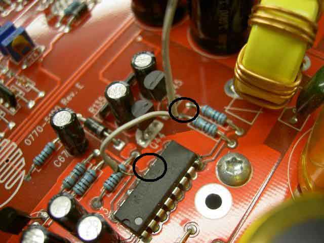
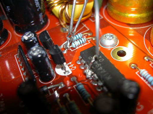
I have to agree over and over again. You should be compensated vast sums of money for the invaluable experience and wealth of knowledge you've shared over the years. I've read and relied upon your responses even before our current correspondence. Pins 11 and 12 were connected to eachother, but they weren't connected to pin 8. However, I feel like they are common now. The picture below should show what I was able to do based upon my understanding of what you wanted me to do. I have a feeling I may have messed up...which is why I'm not going to put it back in the car until I get your vote of approval. Regardless of which 3 I test, they all check out at .3 ohms on the meter and are all well connected. Tomorrow I'll clean the board off real well and make the connections as you directed. I know I won't mess those steps up. https://picasaweb.google.com/Chance.Lester/QuickPics#5260600055381379522 https://picasaweb.google.com/Chance.Lester/QuickPics#5260599966006935074 ------------- "I've only gotten this far because I'm known for making every project 10x more difficult than it ever needed to be."
Posted By: i am an idiot
Date Posted: October 24, 2008 at 3:07 AM
STOP those are not pins 11 and 12 Go back and look at the picture I drew. Just wanted to get that out there as soon as I could. Now I am going to have to go to the previous page and find out what I missed.
Posted By: i am an idiot
Date Posted: October 24, 2008 at 3:14 AM
haemphyst wrote:
i am... (and I mean this with all sincerity) you are AWESOME, man! I have seen you help several people repair different electronics long-distance, and I have to tell you, that is one of the coolest things I have ever seen! You are a super asset to this forum! Thanks for joining us!
Wow thanks for the kudos, I really appreciate it, but boy you sure know how to put somebody on the spot. We don't even have the amp working yet.
Thank you too, Steve
Posted By: i am an idiot
Date Posted: October 24, 2008 at 3:21 AM
NC Stop again, thanks to your picture I just noticed something, See the 2 identical resistors directly beyond the end of the chip? One of the legs of one goes to pin 8? I am guessing that the other resistor feeds pin 11. check with your meter to confirm this. If the other resistor is connected to pin 11, we need to power pin 12 and the other end of those 2 resistors. Notice that they are connected to each other on the other end. Pin 12 and the ends of the resistors that have the trace connecting them together.
Posted By: i am an idiot
Date Posted: October 24, 2008 at 3:39 AM
I circled 11 and 12, but remember we only need 12 and the common leg of the resistors, If of course the other end of one of the resistors is connected to 11. I am sure it will be. You did a very nice job on the soldering. In order to remove the solder from 12 and 13, there is no need to get any desoldering braid, you only need to strip a few inches of wire, twist it to keep the wire from pressing flat when you press on it, place the wire along the side of the chip, heat the wire that is right on pins 12 and 13, as the wire gets saturated with solder, pull it towards you so that a clean piece is on those pins, repeat until you have removed the solder that is bridging those pins.
The pic below tells you where to install the jumpers. Run the 2 wires to the resistors and the short one to pin 12. It is easier to put more wires on the resistors than on the chip.
Posted By: ncchance
Date Posted: November 02, 2008 at 9:27 AM
Once again, I greatly apologize for the delay. But at least now you know why. I just attempted to embed some pics I took of the recent soldering. Sorry, they aren't the bext quality. Nothing is being bridged although it may look like it is from the pics I've posted. I'm hoping I didn't misunderstand your directions. I've had a lot on my mind and confusion has tended to set in lately. I haven't and will not hook anything up until I get the go-ahead from you. I'll be back in Durham (home) sometime early this evening and I'll be able, if directed, to hook it up and get any necessary readings. 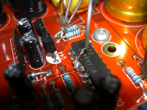
------------- "I've only gotten this far because I'm known for making every project 10x more difficult than it ever needed to be."
Posted By: i am an idiot
Date Posted: November 02, 2008 at 10:03 AM
All looks fine there. As you stated, in one pic it does look as though 12 and 13 are bridged, the other pic shows they are not. You can bring it to the car and remember a single 10 amp fuse, and only connect the power plug. No RCA jacks. With the power plug connected, briefly touch the jumper to the power block or the shiny metal going into the back of the fuse holder. By briefly, I mean about 1/2 of a second, watch the LED when you do this. It should light up. If it lights up and the fuse is ok, the next time try it for a few seconds. If that goes well, connect RCAs and speaker terminal. With the volume turned very low touch the jumper to the fuse again and see if the sub plays. If it plays, this will let us know that there is no major damage. Let me know if it plays. Edit: A soldering tip for you. When attempting to solder a wire to another component or to another wire for that matter, heat up the wire and apply solder to that device, then heat up the other device and saturate it with solder. With solder on each device, now place the devices together where you wish to make the connection. Heat up the 2 soldered devices and when the solder melts, remove the iron and hold in place until the joint cools. Never touch the solder directly to the iron, the iron is hot enough to make the solder melt, if the part you are soldering is not hot enough to melt the solder, you will not make a good connection. Depending on the quality of your iron, you may have to briefly touch the solder to the iron to start the melting process, but the metal needs to be hot enough to melt the solder.
Posted By: ncchance
Date Posted: November 03, 2008 at 6:59 AM
I was able to hook it up as you directed last night and the news I have isn't very good. The only light that was visible was a very faint spark created at the end of the IDE jumper cable whenever I touched it to the power block. I also tried touching the metal rear of the fuse holder, but there wasn't any life from the power LED. Now that I think about it, I don't recall if there was a spark created on the fuse holder the way there was on the power block. Also, I know you said to connect on the power block so that is all that I connected. Did you want me to connect the remote as well? I'm guessing there may in fact be major damage? Using your soldering tips, which are greatly appreciated by the way, I will re-solder the connections to make sure my problem isn't just a couple of bad connections. That is if you think it would even be worth it. I'll be able to resume with much better contact and response times starting at this point. Thank you for your condolences and you're understanding. ------------- "I've only gotten this far because I'm known for making every project 10x more difficult than it ever needed to be."
Posted By: i am an idiot
Date Posted: November 03, 2008 at 8:40 AM
See the 2 transistors next to the chip, they are labeled Q44 and Q45. We need to check them to see if they are shorted. Put your meter on the diode test function, it should be the only little picture on the choice of selections. The pic should be similar to this 
Touch and hold one meter lead to one leg of the transistor, now touch the other lead to the other 2 legs, one at a time of course, and notice the readings. Do this for both transistors and let me know what you find out.
Posted By: ncchance
Date Posted: November 03, 2008 at 4:57 PM
Alright these are the reading I got after testing. In order to keep me from confusing myself I'm numbered each leg of the transistor 1, 2, or 3. 1 being the closest to the RCA inputs and 3 being the closest to the power block.
Q44: 1 - 2 = 0.645 steady
1 - 3 = 1.3 and climbing
2 - 3 = 1.600 and climbing
Q45: 1 - 2 = 0.660 steady
1 - 3 = 0.660 and climbing - Sometimes it reads 0.231 climbs and beeps for a few seconds then stops, and other times it doesn't.
2 - 3 = 0.604 slowly dropping
I don't think I am making any inadvertent contacts. Do these results seem accurate?
-------------
"I've only gotten this far because I'm known for making every project 10x more difficult than it ever needed to be."
Posted By: i am an idiot
Date Posted: November 03, 2008 at 6:07 PM
When performing the following tests, about 30 seconds into it, put your finger really close to the top of the 494 to see if it is getting hot. Do not touch it, it may get really hot. If it is even warm you can stop testing, it is bad. Try connecting the remote lead and the jumper back to the fuse holder. Do you have any alligator clips so you can connect the jumper and have both hands free to take some readings with the meter. With the black meter lead on the ground terminal of the amp, meter to DC Volts, red lead to power terminal, then to the remote terminal, just to verify the amp is getting power. Leave black lead there and check the following pins on the 494. 7 should read 0 8 should read 12 9 and 10 should be around 5. 11 should be the same as 8. 12 should read 12. Let me know what you find out.
Posted By: ncchance
Date Posted: November 04, 2008 at 8:35 AM
Here are the results I got last night. Pin 7 = 0 Pin 8 = .004 Pin 9 = 0 Pin 10 = .034 Pin 11 = 0 Pin 12 = 0 So I've got what is most likely a stupid question. From what I've experienced in the past whenever something isn't working then you come to find something else isn't working...sometimes they have a common fault. This is a shot in the dark here, but I found out last night that the relay I use to run a fan above my HU and to send the remote wire back to my rear amplifiers wasn't working 100%. It wouldn't turn the fan on, but it was switching my other amp in the rear on. Is it possible that this relay hasn't been sending enough juice to power the remotes for two amps? What I've done while the orion amp has been out of commission is running my subs off the amp that typically ran the 6 x 9s in my rear deck. I'm basically running a panaroamic front stage with subs. Perhaps the relay was working just enough to switch the one amp..... Now that I think more about it that is completely inane. If the relay switches at all it is switched and that's just that. Correct? Also, it wouldn't have a whole lot to do with the readings I'm getting from the pins of the 494 because we're sending direct power to the amp. I don't know...I think I'm just grabbing out at anything in desperation. I went ahead and replaced the relay with one I had laying around. The fan started working again. If you think it'd be worth it I can get new readings after work and let you know what I get at about 4:45 - 5:00. Haha, if you feel the need to berate me, go ahead, I'll understand. lol ------------- "I've only gotten this far because I'm known for making every project 10x more difficult than it ever needed to be."
Posted By: ncchance
Date Posted: November 04, 2008 at 8:41 AM
I forgot to mention that switching the fuse locations gave me different readings at the pins. I wrote them down on a different slips of paper, but I must have lost it somewhere. The only difference I can recall was at pins 8 and 12 where I got 0.345 for both of them.
-------------
"I've only gotten this far because I'm known for making every project 10x more difficult than it ever needed to be."
Posted By: i am an idiot
Date Posted: November 04, 2008 at 8:12 PM
8 and 11 should have near 12 volts. Pin 12 should have 12 volts on it. You must have a bad solder joint on pin 12. You are connecting the wire from pin 12 to the fuse. You need to figure out why there is not 12 volts on pin 12.
Posted By: ncchance
Date Posted: November 04, 2008 at 9:04 PM
I was reading over the past few posts and somehow I inadvertantly overlooked the sentences about the 494 getting warm. That being the case I paid no attention to how it responded. After I resolder all of the jumper's joints I will run the test again and make certain to pay attention to the 494's response.
-------------
"I've only gotten this far because I'm known for making every project 10x more difficult than it ever needed to be."
Posted By: i am an idiot
Date Posted: November 04, 2008 at 10:32 PM
You need to figure out why there is no voltage on pin 12. Without power there, it will not get hot.
Posted By: ncchance
Date Posted: November 05, 2008 at 7:21 AM
Haha, good point. Need I mention the fact that I'm slightly retarded? I didn't do anything yesterday because I worked until 10:00 last night, but hopefully I'll get the chance to work on it this evening.
-------------
"I've only gotten this far because I'm known for making every project 10x more difficult than it ever needed to be."
Posted By: i am an idiot
Date Posted: December 30, 2008 at 6:01 AM
You should have received the amp and the parts by now. Let me know what you figure out with the parts. Hope you had a good Christmas.
Posted By: ncchance
Date Posted: January 21, 2009 at 10:04 AM
I received the amp and the extra parts to repair the other amps. With your help I was able to replace the output transistors and get the US Acoustics working again. I have yet to repair the JL amp that I canabalized for its transistors, but that should be a breeze. I would have been completely done for without your help! I can't begin to explain how grateful I am for your work/assistance/patience/expertise/time...the list goes on and on. You are of extrodinary value to The12Volt.com!!! The amp works like a champ and it even performs better than ever! It turned out to be bad solder joints on both fuse blocks, one bad transistor, and a defective LED. There is no way I'd have even known how to check or even being to repair those problems. You did it all for a minimal cost and fast shipment! I will sing your praises for as long as you'll let me! Thanks again and best of luck in the new year! ------------- "I've only gotten this far because I'm known for making every project 10x more difficult than it ever needed to be."
|