adding a wired remote volume switch
Printed From: the12volt.com
Forum Name: Car Audio
Forum Discription: Car Stereos, Amplifiers, Crossovers, Processors, Speakers, Subwoofers, etc.
URL: https://www.the12volt.com/installbay/forum_posts.asp?tid=113541
Printed Date: May 16, 2026 at 8:28 AM
Topic: adding a wired remote volume switch
Posted By: fatfenderfan
Subject: adding a wired remote volume switch
Date Posted: May 01, 2009 at 6:48 PM
I have an inexpensive AM/FM unit that I want to install in a specialty car. I want to install a wired remote on/off volume switch. I do not want to remote the treble/bass switch. I have photographed the original switch which you can view here. My questions are: (1) How do I ID the wires for the on/off circuit and (2) the volume control circuit. Once I have ID'd the right wires I want to change them over to the remote switch which would be, of course, a simple pot with off/on control (but I don't even know what kind to get). I have played around with my VOM trying to isolate the off/on switch but have not even been successful there. I have just enough understanding of stuff at this level to not be considered 'ignorant', but do qualify as 'dangerous'! Thanks for any help.
Replies:
Posted By: i am an idiot
Date Posted: May 01, 2009 at 7:37 PM
Can you take a photo of the bottom of the board. Take it square with the board. The power switch is the one with only 2 connections. All of the audio adjustments have 3 connections. I am pretty sure that the 2 sets of 3 connections directly toward the front of the control from the power connection is the left and right volume. The picture will help me confirm this.
Posted By: fatfenderfan
Date Posted: May 01, 2009 at 9:21 PM
Not only 'thanks for the fast reply', but 'thanks for the fast RIGHT reply'!
While I went ahead and posted the pic you requested to the end of that same album, given what you said I verified that the '2 connections' are off/on, and the next set of 3 (to the right in the pic) are the volume. But I am confused about the reading on those three. (Lets label them 1,2, and 3, top to bottom). When I check resistance between 2 and 3 it ranges from 4.5 ohms to 15.65k ohms. When I check between 1 and 2 its almost constant at 2.2 ohms. Does that make sense to you? Also, when shopping for a pot, what should I ask for?
Posted By: i am an idiot
Date Posted: May 01, 2009 at 9:35 PM
Volume is on the other side of the power switch, there are 2 for volume, one set for left and the other set for right. Off/On is correct. Volume are the 2 sets to left of on off.
Radio shack sells a 100K ohm stereo potentiometer, only problem is there is no on/off switch. They do sell a pot with on/off, only problem there is it is only one channel. 271-1732 is the part number for the stereo pot.
Notice the 2 bottom connections of the 2 sets of connections are connected together. That is the ground connection. The connections directly above the jumped ones are the wiper of the pot. That is output of the pot. The top connections are left and right signal.
Posted By: i am an idiot
Date Posted: May 01, 2009 at 9:38 PM
It would probably be easier to move the entire board and shaft. How far away are you needing to move it?
Somewhere on your camera there is a picture of a flower. This is the macro function, it allows your camera to focus in an extreme close up situation. Try selecting that and take another pic just like the last one. I am having trouble seeing the traces on the left side of the board.
Seriously, as long as you are not trying to move it several feet away, and you have somewhere you can mount the pot and circuit board, it will really be easy to move the entire setup.
Posted By: fatfenderfan
Date Posted: May 01, 2009 at 10:59 PM
First, I did use 'close-up'. But obviously my technique needed some work. I just went through that drill again and posted a much better shot.
OK, now you are forcing me to be completely honest... I don't have the option of moving the original switch because I am in the process of mfgr'n a replica of the original radio head from a 30's vintage vehicle. You see, back then the big old clunky radio was mounted up against the firewall with a couple of mechanical inner/outer drive cables running up to a small radio head in the dash. The radio in question is a new mfgr unit with a manual tuner (so I can sinc the dial mechanically) . I am remoting the manual tuner and have that worked out. I also have the front/rear control worked out. But I cannot remote the original volume control because I would have to have the bigger, inner knob for the treble/bass control show, and that is not an option. Also, because the 'treble-bass' and 'balance control' are 'push to engage', the knob would stick out to far. Not acceptable. My ultimate desire is to have the radio head look as close as possible to original, but have the radio itself located in a hidden, but accessible location for adjustment of those seldom used controls. Just so's you know what I am talking about I have posted a photo of what I am doing. I have digitally remastered the original face, found a source for the the needle and lens, and have worked out how to reproduce the plate, and original knobs (not shown it photo).
So now I am a whole lot less confused than when I started this thread but now I need to figure out how to isolate the on/off, volume control. It should have been obvious to me from the beginning that the orange and red were on/off (daaa) but I see now that it seems like there are (2) pair of red-black-white wires. Yet there are (5) circuits; (1) bass/treble (2) left/right (3) front/rear (4,5) volume. How do I isolate just those wires so the original switch (in its original location) controls everything but on/off, volume. And the remote switch just handles on/off; volume.
Posted By: i am an idiot
Date Posted: May 02, 2009 at 2:18 AM
Do you understand parallel and series wiring configurations? I will draw you a picture tonight. All you need to do is parallel the new pot with the volume section of the old one. Same with the power. You will have to leave the volume level on the actual radio volume control set to a pretty high volume level, Either on/off will turn radio on. They will both have to be off to turn the radio off. Either volume control will adjust the volume level of the radio up to the volume level set on the other volume control.
I hope you can find a stereo pot with an integrated power switch. It has been many years since the search, but we searched high and low for such a piece, no luck, but that was before the internet was available.
Posted By: fatfenderfan
Date Posted: May 02, 2009 at 8:41 AM
"Yes" to your first question. Thanks for taking the time to produce a drawing for me. I will be looking forward to seeing it.
Posted By: i am an idiot
Date Posted: May 02, 2009 at 4:34 PM
Did you get a 271-1732 from Radio Shack? If so take a pic or it with the shaft facing left and the 6 connections facing the camera. I will use the 2 pictures and run wires between them. 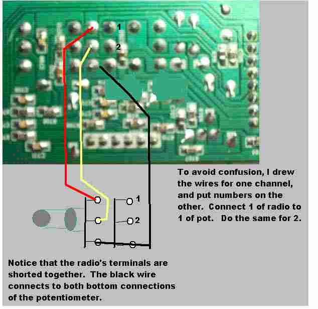
Posted By: i am an idiot
Date Posted: May 02, 2009 at 9:03 PM
You should use shielded cable to do this. The black wire is the shield of the cable. Radio Shack sells a suitable cable.
Connect both shields to the radio and to both bottom connections of the potentiometer.
Posted By: fatfenderfan
Date Posted: May 03, 2009 at 1:44 AM
Great. Got it. You have already given this more effort than I could have expected so I went ahead a drew up what I think you were going to do. Maybe you can check it.(Pic is tacked on to the original album.) Also think I may have stumbled across what might be a cute little trick by way of a stereo pot WITH on/off switch. Along with the 271-1732 I picked up a 271-0215. I noticed there is a perfect little hex drive on the back of the 1732. I plan on cobbling up a coupler to drive the 0215. Waa-Laa... an endless supply of 100k ohm stereo pots WITH on/off for under 8 bucks! You can see pics of this on that album too.
Posted By: i am an idiot
Date Posted: May 03, 2009 at 6:27 AM
I just realized we may have a tiny problem. You will have to completely disconnect the power switch on the main volume control, remember I said either switch would turn the unit on. And either volume control would control volume up to the level of the highest set volume control. With the radio control off, the volume will be at 0. You will have to keep volume up on the radio volume control. This will have the power switch always on. You will not be able to turn it off via your new switchometer. You will have to cut the red and orange wires and run them to the new switch. If you do not want to cut the wires, you can solder wires to the connections on the bottom of the board and cut one of the traces going to the switch on the radio board.
Also you should use a couple of zip-ties to secure the shielded cable to the board of the radio. That cable is not very tough, just the moving around while mounting it will likely break the wires at the solder connection.
Posted By: fatfenderfan
Date Posted: May 03, 2009 at 1:28 PM
I was wonder'n about your original idea of off/on. This one I get.
Armed with all this info I will get to work and see if I can make it all happen. Will let you know what the outcome is if you would like...
Posted By: i am an idiot
Date Posted: May 03, 2009 at 1:55 PM
It would be nice to know if you get it working. One more thing, you will need to figure out which of the 2 wires are the hot feed to the board. Cut only that one or cut that trace. The output of the switch on the board feeds other components on that board. Edit: The red wire is the hot wire. Cut it and send it only to the new switch. Connect the other terminal of the switch to the Orange wire or to the terminal of the switch that connects to the orange wire.
|