Sony 16 Pin Diagram
Printed From: the12volt.com
Forum Name: Car Audio
Forum Discription: Car Stereos, Amplifiers, Crossovers, Processors, Speakers, Subwoofers, etc.
URL: https://www.the12volt.com/installbay/forum_posts.asp?tid=113843
Printed Date: November 23, 2025 at 3:49 PM
Topic: Sony 16 Pin Diagram
Posted By: pv13
Subject: Sony 16 Pin Diagram
Date Posted: May 16, 2009 at 7:13 PM
I have a Sony CDX-C5050X CD player but with no harness. This unit is 9 years old, and I am only using it as a shop radio, so I don't want to put anymore money into it by purchasing a harness.
Does anyone know what the pin diagram might be for this 16 pin harness? Or is there a way to test which wire is which?
Thanks
Replies:
Posted By: i am an idiot
Date Posted: May 16, 2009 at 7:40 PM
I can help you figure out what is what. Is there a fuse on the back of the unit? Do you have a digital multimeter? With the meter set to the diode test function, this is the symbol that should be on that setting.  Attach the black lead of the meter to the chassis of the radio. Now touch the red lead to each of the pins on the plug. One pin will beep at you and read very near 0.000. Label that pin as ground. There will be 8 pins that have the same exact reading. Those are speaker wires. We will get to that later. If there is a fuse, you should be able to get a meter lead on the element of the fuse, there is a hole on each side of the fuse that allows access to the element. One lead on the fuse other lead to the remaining unidentified pins, one of them will read very near 0.000 label that one as constant voltage. You should have only 2 or 3 unidentified pins now. Draw a picture of what you found or take a pic and label what you have found, I can tell you where the switched wire is located. Attach the black lead of the meter to the chassis of the radio. Now touch the red lead to each of the pins on the plug. One pin will beep at you and read very near 0.000. Label that pin as ground. There will be 8 pins that have the same exact reading. Those are speaker wires. We will get to that later. If there is a fuse, you should be able to get a meter lead on the element of the fuse, there is a hole on each side of the fuse that allows access to the element. One lead on the fuse other lead to the remaining unidentified pins, one of them will read very near 0.000 label that one as constant voltage. You should have only 2 or 3 unidentified pins now. Draw a picture of what you found or take a pic and label what you have found, I can tell you where the switched wire is located.
Posted By: pv13
Date Posted: May 18, 2009 at 12:23 AM
I believe I found the constant 12 volt, ground, and speaker wires, but there is still 6 wires that I haven't identified. 4 of the pins didn't fluctuate from the OL on my multimeter, while the other 2 gave me some readings.
Thanks
Posted By: i am an idiot
Date Posted: May 18, 2009 at 1:37 AM
7 or 15 is switched. probably 7. It really does not matter from here. The only wires left are Switched, remote, power antenna, and possibly a mute wire (not likely on a Sony). The good thing about that is any of those wires will NOT be damaged by applying 12 volts to them. Solder your wires on ground and constant, connect them to the appropriate battery terminals. Now touch another power wire to 7 and turn the radio on. If it comes on solder that wire there. If not try it on 15, one of them is switched. Once you get that, we need to find out if speaker wires are 1,2 3.4 or 1,9 2,10. In order to figure this out, balance to the left and fade to the front. wire up a speaker and touch the wires to 1,2 3,4 9,10 11,12 Then from 1,9 2,10 3,11 4,12. Several of these combinations should make sound. One combination will be considerably louder. Make note of the louder pair. Balance right, and do it again with the remaining wires. Label the louder pair. Fade rear and do it again. Label that pair. If it is 1,9 2,10 etc. 9 10 11 and 12 are your positive wires. If it is 1,2 3,4 9,10 11,12 2,4,10,and 12 are your positive wires.
It is hard to identify the switched wire with a meter. It is simply a voltage sensing wire. it pulls no current through that wire. If it did pull current it would make the meter react.
Posted By: pv13
Date Posted: May 18, 2009 at 4:52 PM
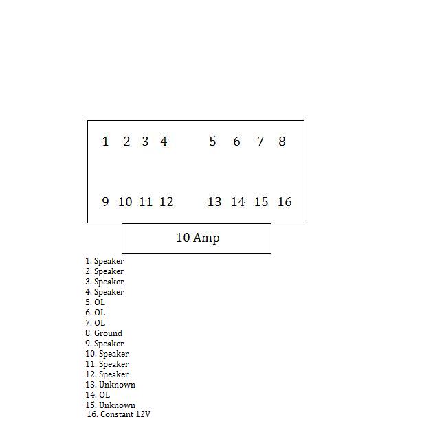
The switched 12v was number 7. And the speakers were as follows:
Front Left: 1,9
Front Right: 4,12
Rear Left: 2,10
Rear Right: 3, 11
Thanks for your help.
Posted By: i am an idiot
Date Posted: May 18, 2009 at 5:58 PM
Glad you got it working.
|