pg octane 900.5 repair
Printed From: the12volt.com
Forum Name: Car Audio
Forum Discription: Car Stereos, Amplifiers, Crossovers, Processors, Speakers, Subwoofers, etc.
URL: https://www.the12volt.com/installbay/forum_posts.asp?tid=114723
Printed Date: March 25, 2026 at 10:08 AM
Topic: pg octane 900.5 repair
Posted By: ianarian
Subject: pg octane 900.5 repair
Date Posted: June 27, 2009 at 6:32 AM
My brother crossed polarity on the power and ground terminals of this amp. The 40a fuse for sub obviously smoked. Both 25a fuses for Front and Rear are fine. The amp still plays fine as a 4ch. The 5ch smokes fuses though. I gave him a new amp but was wondering if there is something we can do to get the sub line working again.
-------------
This is what I do for FUN!
Replies:
Posted By: i am an idiot
Date Posted: June 27, 2009 at 3:28 PM
If the amp was properly fused, there should have not been any damage. If you have an Ohm meter and a digital camera, And can answer some questions, I am sure we can figure out what the problem is. If polarity was reversed, it would have blown all of the fuses. ------------- Let's Go Brandon Brown. Congratulations on your first Xfinity Series Win. LGBFJB
Posted By: ianarian
Date Posted: June 28, 2009 at 3:27 AM
To the best of his recollection only the 40a blew.(comming from the guy who reversed wires in the 1st place) Uh huh, anyway I got the meter but I think I need to get ya a clearer pic. 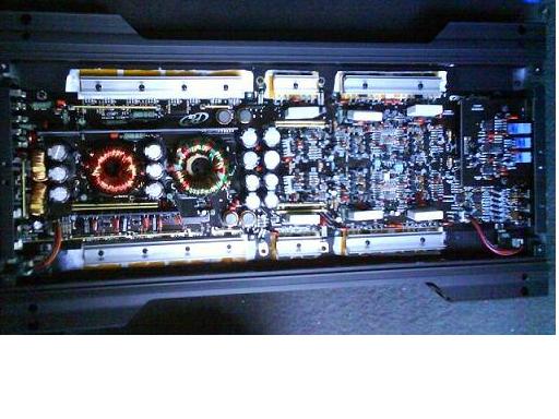 ------------- This is what I do for FUN!
Posted By: i am an idiot
Date Posted: June 28, 2009 at 7:45 AM
That picture will do for now. Place a 10 amp fuse in the slot that is blowing. I need you to connect only the power wire and the ground wire. Do not connect the remote wire. Does the fuse blow with only power and ground connected?
Posted By: i am an idiot
Date Posted: June 28, 2009 at 8:20 AM
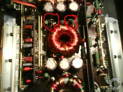
Do not remove the clamps from the heat sink unless we determine it is necessary. The cleanliness of the bond of the transistors to the heat sink is important. The less time it spends apart the better off we are. If it blows the fuse without the remote terminal connected, the problem lies in the power supply area. If it only blows the fuse when remote power is applied, the problem lies in the output devices. Look for the large diode to the left of the picture. There may or may not be one. 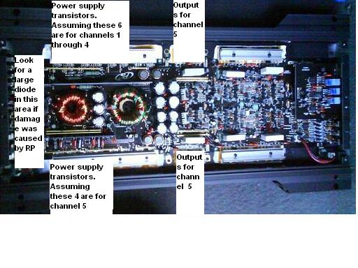
Posted By: ianarian
Date Posted: June 29, 2009 at 1:29 AM
It blew a 10a without the remote hooked up. I dont see a diode that stands out as large. There is one that I would consider the larger than the rest though.
-------------
This is what I do for FUN!
Posted By: i am an idiot
Date Posted: June 29, 2009 at 6:01 AM
With your meter set to the diode test function, it should be the only setting with a symbol. It is the symbol for a diode.  Remove all fuses from the amp, There are 3 legs on each of the power supply transistors. Place and hold one meter lead to the center leg of the first transistor, now touch the other lead to another leg of the same transistor. Write down that reading. Now move the last lead to the other leg ot the transistor. Write down that reading. Move to the next transistor. Repeat. On either the set of 4 or the set of 6 there will be one or more of them that read very near 0.00 This is the problem set of transistors. Once you figure out the shorted set, remove the clamp from that set of transistors so we can get the number off of the top of the transistor. If you can not read the numbers, place your finger in some of the white heat sink grease and rub it onto the top of the transistor. Wipe most of it off and you will be able to read the number.
Posted By: ianarian
Date Posted: June 29, 2009 at 8:50 PM
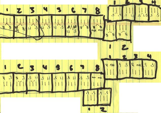
Hope this makes sense but its arranged just as we see the amp in the other pick. I metered every transistor under the heat sinks. Some say max because the meter kept going up until 2.0 where it went to open circuit. 0 obviously didnt get a reading. Looks as if every heat sink but 2 has a bad transistor under it. I'll grab those #'s for ya too. ------------- This is what I do for FUN!
Posted By: i am an idiot
Date Posted: June 29, 2009 at 9:02 PM
It appears as though the amp has shorted output transistors. There is no way connecting the amp backwards shorted these components. The output transistors shorted and in turn took out the power supply.
With your meter set to the diode test function, what does it read when you hold the leads together?
The transistor on the top left of the picture is definitely shorted. I am 99% sure the ones at top right of this picture are shorted. I need the info about your meter to be sure.
Posted By: ianarian
Date Posted: June 30, 2009 at 3:10 AM
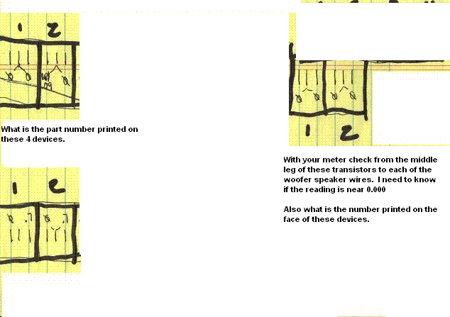
All four transistors are labeled DFP50N06/4206.
The other 2 separate transistors cycle to .OL, when the common lead is on the transistor side and the red lead is on either +/- sub terminal.(SWITCHING LEADS) If the common lead is on the sub side then im getting .903 across both transistors mid leg to sub(+), and .491 from both transistors mid leg to sub(-). Transistor #1 labeled-TIP36C/() 638. Transistor #2 labeled-TIP36C/ () 636.
My meter is a Wavetek Meterman...it reads .000 at lead tips.
My brother is a journey inside wireman and admitted the reversing mistake. Which must of been hard to do. He knows what he's doin by all means. Hmmmm something fishy goin on here!
-------------
This is what I do for FUN!
Posted By: i am an idiot
Date Posted: June 30, 2009 at 5:33 AM
We need to cut the legs off of the top left transistor and both of the TIP 36 transistors. Cut the legs off as close as you can to the case of the transistor. After cutting each leg, move it a bit towards the center of the board to make sure it is not making contact with the transistor. REPLACE ALL of the clamps that you removed, Place a 10 amp fuse in the slot that has been blowing. And if you have (2) 5 amp fuses, place them in the other 2 slots. Place the amp back in the vehicle and connect power ground and remote. It may or may not blow the 10 amp fuse, if it does not blow the fuse, Set your meter to the DC Volts selection. I need to know the DC voltage from the outside legs of the 4 power supply transistors. 2 on top of pic and 2 on bottom of pic. These are the only 4 parts that we are concerned about at this time.
Posted By: ianarian
Date Posted: June 30, 2009 at 7:00 PM
For now I got the amp on my bench its covered and clean and well lit. The 10a sub fuse blew as soon as I switched on remote.
-------------
This is what I do for FUN!
Posted By: i am an idiot
Date Posted: June 30, 2009 at 7:11 PM
How many transistors did you cut out of the circuit?
Posted By: ianarian
Date Posted: June 30, 2009 at 7:32 PM
3 total
-------------
This is what I do for FUN!
Posted By: i am an idiot
Date Posted: June 30, 2009 at 8:22 PM
Check the transistors directly across from the TIP36Cs. They should be TIP35Cs. Also check these from the left leg to the right leg. Also recheck the one remaining transistor at the top left of the pic, and the 2 at the bottom left of the picture. Also there is a resistor connected to the left leg of each of the power supply transistors. The transistors in the top row of the pic are positioned correctly. The bottom row are positioned opposite. The resistor will be connected to the left leg of the top row and the right leg of the bottom row. Using the meter now set to the Ohms selection, what is the reading of the 4 transistors we are checking now? Is the resistor that was connected to the top left discolored or burnt?
Posted By: ianarian
Date Posted: July 01, 2009 at 12:32 AM
Yes they are tip35's, lookin at the face/label the 3 legs commming down, are they B,C,E in that order? Lets say that the (Center to Left) legs-.551 on both tip35's. (Center to Right) leg is .OL on both tip35's
the one remaining transistor at the top left of the pic-1.13(C-L) .460(C-R)
and the 2 at the bottom left of the picture.(C-L)1.130 (C-R).458 same for both
I didnt get a ohm reading on the four transistors, testing them in the same fashion as the diode tests.C-L,C-R
All the resistors look ok/same too.
-------------
This is what I do for FUN!
Posted By: i am an idiot
Date Posted: July 01, 2009 at 5:21 AM
Cut out the other transistor top left of your diagram. Try the fuse again. We may have a problem with the driver transistor that drives the 2 top transistors. I need to know the value of the resistors, and also follow the trace from the other end of the resistor. It will go to a small transistor. It may go to 2 transistors. I need the number on both of those transistors.
Posted By: ianarian
Date Posted: July 01, 2009 at 4:38 PM
Ok, she blew a 10a when remote switched on..
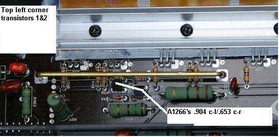
our two little transistors are both labeled K/620/A1266/Y
the resistors are yellow, purple, black, gold they metered to 46.2ohm
Posted By: i am an idiot
Date Posted: July 01, 2009 at 6:44 PM
The A1266s I am assuming that one is connected to the resistors in top of pic and the other is connected to resistors in the bottom of the pic. With your meter I need ot make sure both of these give the same readings as the other one. Check all possible combinations of leg and lead positions. Also check the 35s from left leg to right leg.
Posted By: ianarian
Date Posted: July 01, 2009 at 10:58 PM
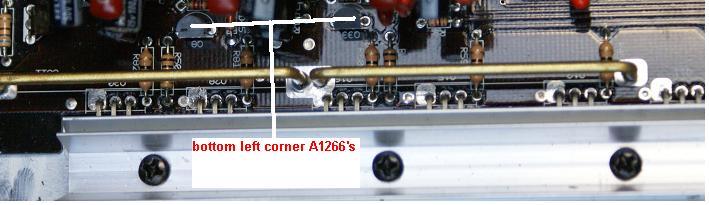
There is no continuity across the L and R legs of the 35's. I located 4 total mini transistors all appearing to be branched of the resistor as we discussed which all have the same reading. center-Leg1 .904 / center-leg2 .653. Reading displays promptly and stable.
 ------------- This is what I do for FUN!
Posted By: i am an idiot
Date Posted: July 02, 2009 at 5:27 AM
We are going to have to replace all 4 of the power supply transistors, so cut the bottom 2 out also. But cut them as close to the case as possible. Bend the legs so that they are perpendicular to the board. Do not cut these near the board. This will make it much easier to remove the legs when it comes time. After you cut these 2 out, reinstall all clamps and another 10 amp fuse, (it will not blow this time) Power it up and set your meter to DC volts. One lead on left leg and one lead on right leg. It should be near 5 Volts on each of the transistors. I am thinking that one pair is going to be lower or higher than that. Also there should be a chip with about 16 pins on it. I need to know the number, it will be XX494 or XX594 or XX352X. One of the other legs of the 1266s will go to that chip.
Posted By: ianarian
Date Posted: July 02, 2009 at 10:17 PM
Ok my kind sir, yes we had just about 5v on the remaining power supply transistors. There are two chips that may be the ones your speaking of: They both are labeled S63525A they sit vertically on a separate board. They got 8 pins to each side of them.
 ------------- This is what I do for FUN!
Posted By: i am an idiot
Date Posted: July 02, 2009 at 10:36 PM
I am not worried about the remaining transistors. What is the voltage on the 4 that you removed? Yes those are the chips I was asking about. If you have 5 volts on the 4 that were removed, we have something else pulling current on the audio section.
Posted By: ianarian
Date Posted: July 03, 2009 at 7:30 PM
Yes we do have the 5v on the 4 removed transistors....my bad misunderstood ya.
-------------
This is what I do for FUN!
Posted By: i am an idiot
Date Posted: July 03, 2009 at 10:20 PM
I am having trouble locating those exact power supply transistors. If I can not find them, I do know a replacement that will work. I may have to make a call Monday.
Posted By: ianarian
Date Posted: July 05, 2009 at 4:44 PM
In my area we have a store called electronics plus. Here lemme posta link: [URL=https://www.electronicplus.com/]
try this store
-------------
This is what I do for FUN!
Posted By: i am an idiot
Date Posted: July 06, 2009 at 7:59 PM
I can not find anything on their website. If you could call them or go by there and see if they carry the TIP36s and an IRF-Z44. Preferably the International Rectifier brand. If they try to sell you an NTE cross reference, you would be better off ordering the originals from DigiKey.com or Mouser.com Thinking back, there is still possibly something shorted, that is why the fuse kept blowing when the power supply transistors were still in the amp. When we removed them and verified that there was around 5 volts on the gate of the transistor, this leads me to believe that there is still a problem with the audio section. While you are ordering, go ahead and get a couple TIP35s also.
Posted By: ianarian
Date Posted: July 09, 2009 at 4:14 AM
Ugg, had some emergency outta town biz...so Ima order this:
6.)-tip36's
4.)-tip35's
1.)-IRF-Z44
I got to leave for LA again this weekend but I'll get the order in before I leave.
-------------
This is what I do for FUN!
Posted By: i am an idiot
Date Posted: July 09, 2009 at 5:47 AM
You need 4 z44s and 2 each of the others,
Posted By: ianarian
Date Posted: July 09, 2009 at 10:07 PM
YA, Idiman thats what I meant  , I was just using technical terms and stuff...  ------------- This is what I do for FUN!
Posted By: i am an idiot
Date Posted: July 09, 2009 at 10:27 PM
When you get the parts in, I still think that there is a problem somewhere. You need to go to radio shack and purchase (4) 8 ohm 20 watt resistors. Parallel these resistors to yield a 2 ohm load. We need to insert the resistors in series with the power wire. This will limit the current draw of the amp to around 7 amps of current. This will be very important when we power it back up. We have to monitor the temperature of the resistor to see if something is drawing current.
Posted By: ianarian
Date Posted: July 10, 2009 at 6:41 PM
Roger Dodger...Crap, my tip36's came in so far and they are NTE. Ima return them. Dude swears they are exactly the same and if they dont work....then there's another problem. HUH! Ima tell him to worry about getting me the right parts, this stuff usually escalates to a verbal assault. He knew what he was ordering, restock fee my @$$!
-------------
This is what I do for FUN!
Posted By: ianarian
Date Posted: July 14, 2009 at 1:04 AM
Ok, the resistors were easy. Are we on hold with those until the transistors arrive?
-------------
This is what I do for FUN!
Posted By: i am an idiot
Date Posted: July 14, 2009 at 6:56 AM
Pretty much.
Posted By: ianarian
Date Posted: July 14, 2009 at 9:07 PM
Aight, I'll need a lil bit of time, I dont make any internet purchases, ever. That local store couldnt get us the right stuff. So, I got 2 stores to check that claim they have what we need but they're a coupla divetry miles away. Do NOT forget about me though non-idiot. I have learned a lot and have had fun working on this. It wont be too long.
-------------
This is what I do for FUN!
Posted By: i am an idiot
Date Posted: July 14, 2009 at 9:14 PM
'm not going anywhere. Just let me know when you get the parts.
Posted By: ianarian
Date Posted: August 01, 2009 at 9:59 PM
GAAAA, Im not good at sourcing parts.....Or these dam resistors are obsolete. The sites keep claiming they are in stock and when I order them(which I've had to resort to) they comeback saying out of stock~! SOB's take all my info too. Got any other places I can try?
-------------
This is what I do for FUN!
Posted By: i am an idiot
Date Posted: August 02, 2009 at 6:54 AM
If you are having trouble finding the 8 Ohm 20 watt resistors, go to an auto parts store and purchase an old sealed beam dual element headlamp. I do not remember the number, it is a round headlamp that has high and low beam elements.
-------------
Let's Go Brandon Brown. Congratulations on your first Xfinity Series Win. LGBFJB
Posted By: ianarian
Date Posted: August 02, 2009 at 10:15 PM
Did I say resistors? heh My bad I meant transistors...can you check these, make sure they are right? If so, I should be able to get these!
https://www.alliedelec.com/Search/ProductDetail.aspx?SKU=2480467&MPN=TIP35C#tab=Specs
https://www.alliedelec.com/Search/ProductDetail.aspx?SKU=2480468&MPN=TIP36C#tab=Specs
-------------
This is what I do for FUN!
Posted By: i am an idiot
Date Posted: August 02, 2009 at 11:11 PM
Yes the SGS Thompson devices should be fine.
-------------
Let's Go Brandon Brown. Congratulations on your first Xfinity Series Win. LGBFJB
Posted By: ianarian
Date Posted: September 10, 2009 at 8:06 PM
The eagle has landed...I got 4-resistors, 4-z44's, 2-tip35's and 2-tip36's
-------------
This is what I do for FUN!
Posted By: i am an idiot
Date Posted: September 10, 2009 at 9:09 PM
I will re-read later tonight and get back to you then or tomorrow evening.
Posted By: i am an idiot
Date Posted: September 12, 2009 at 9:24 PM
If you have verified that there is 5 volts on the left leg of each of the power supply transistor pads, and you have the resistors or the light bulb to limit the current, we are ready to start installing the parts. Do not turn the amp on without mounting it back into the heat sink. And you must install the resistors or the light bulb in series with the power wire. When soldering the parts back in, the left leg of the power supply transistors are very critical that you get a good solder connection. It is really essential that all of the solder connections are good. But if there is a bad connection on the left leg of the power supply transistor will cause that transistor to turn on full throttle, and that will not be good at all.
Posted By: ianarian
Date Posted: September 13, 2009 at 1:46 AM
alrighty then..
- Install all 3 fuses back to the rated Amps
- resistors paralleled to 2 ohm's, in series to +12v
- verify 5v on all left legs
- remove existing pins from board, solder in new components
- verify connection quality
- reassemble all pieces and parts, including heat sinks
- check back in before energizing
-------------
This is what I do for FUN!
Posted By: i am an idiot
Date Posted: September 13, 2009 at 4:16 AM
Using your ohm meter, (if you have not done this yet) we need to check the resistors connected directly to the left leg of the power supply transistors. They should all be the same value. If one is not in tolerance it needs to be replaced. We need to put a single 5 amp fuse in the fuses for each supply. I think I remember that there are 2 separate sets of fuses. One for the 4 channel section and another set for the Sub channel. If this is the case, one 5 amp fuse in each of the 2 banks of fuses, for a total of 2 fuses. When you do turn it on, you need to leave it on for only 5 seconds then turn it off. When you turn it off, touch the resistor briefly to see if it is hot or warm. If not warm, try it for 10 or 15 seconds and repeat. While it is on for these brief periods, check the left leg of each power supply transistor, if any of them are different than the pack, stop and post your findings.
Posted By: ianarian
Date Posted: September 13, 2009 at 7:13 PM
All resistors re-checked and good. Ya, I got 2-25a fuses for the Front and Rear. It was the 40a for the sub that wouldnt hold. All loaded with 5a for now. My gun isnt cutting it, its on its death bed...Ima go get another one tonight. The legs are a little difficult to remove, Im taking care not to damage anything.
-------------
This is what I do for FUN!
Posted By: i am an idiot
Date Posted: September 13, 2009 at 7:47 PM
Do not even attempt this using a gun type soldering iron. If you have to purchase an iron, at least look into a Weller branded iron. A WP-35 shuld work well for you.
https://www.amazon.com/Weller-Watts-Professional-Soldering-3-wire/dp/B000WT6LOI
It may be easier to cut the legs off of the parts and remove them one leg at a time. Cut them as close as you can to the case of the transistors.
Posted By: tommy...
Date Posted: September 14, 2009 at 7:46 AM
I am doing the same thing...A few were easier just cutting legs and pulling with a pair of needle nose...! Others i would just put my tip on the leg...it would heat up...then push it through the board...Just thought i would add that...!...
-------------
M.E.C.P & First-Class
Go slow and drink lots of water...Procrastinators' Unite...Tomorrow!
Posted By: ianarian
Date Posted: September 15, 2009 at 5:56 PM
Yea, I got a weller now, its a pen type...you people are crazy, this tedious stuff is nuts. Anyway, I got all the transistors in and am ready to screw in the heat sinks. Do I need to add any white grease to the backs of the new sinks? Or is what is left on the little plastic sheet enough?
-------------
This is what I do for FUN!
Posted By: i am an idiot
Date Posted: September 15, 2009 at 7:56 PM
The heat sink compound is essential for the transistors to be able to dissapate the heat. Radio Shack sells a small tube that should be enough to handle your job.
Posted By: ianarian
Date Posted: September 15, 2009 at 11:56 PM
I borrowed some from the lab guy at work... He is from Loiusana too! Tomorrow, I get out the bench and try testing. Do the resistors stay on still? Then what type of test should I do on the transistors? Voltage between center and outer legs?
-------------
This is what I do for FUN!
Posted By: i am an idiot
Date Posted: September 16, 2009 at 12:29 AM
With the 2 Ohm resistor in series with the power wire, turn the amp on for 10 seconds and check the resistor for heat. If it is not hot, try it for 20 seconds check temp again. If possible during the 20 second run, check the voltage on the left leg of each of the power supply transistors. Black lead on the ground terminal of the amp or the ground terminal of the power supply. Red lead on the left leg of each transistor. After you get these voltages, check the resistor for heat again. It will hopefully be only a few degrees above ambient. Next time you turn the amp on, check the voltage from the power terminal of the amp to the ground termina of the amp. Our goal voltage is 12 or so. Let me know what you come up with.
Posted By: ianarian
Date Posted: September 17, 2009 at 5:34 AM
OK Idi, we got 7.5v on the input terminals to the amp...The resistors get pretty warm, but not too hot. All 5a fuses are holding, and the voltage readings are as follows. The yellow circles are the replacements we made. 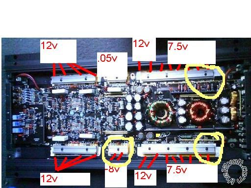 ------------- This is what I do for FUN!
Posted By: i am an idiot
Date Posted: September 17, 2009 at 6:15 AM
The 7.5 volt reading has to be on the middle leg of the z44s. What is the voltage on the left leg? Black lead on ground terminal and red lead on the Left leg of each of the z44s. Left leg is the leg connected to the resistors you checked earlier.
Posted By: ianarian
Date Posted: September 17, 2009 at 10:05 AM
Solder High....They all make the same reading, initially like 1.4 then settles into a .05(+/-) on the 20VDC setting.
-------------
This is what I do for FUN!
Posted By: i am an idiot
Date Posted: September 17, 2009 at 8:22 PM
Pull the fuses out of the power supply that you worked on. Power it back up and check the voltage across the power and ground terminals of the amp. Let it run for 20 seconds or so, and see if the resistors are still getting warm. Check the voltage on the left leg of each of the running power supply transistors.
Posted By: ianarian
Date Posted: September 19, 2009 at 2:17 AM
Ok, the battery on my bench is a little low it has around 11v at the terminals. But its a standard car battery. The amp terminals read 8.3v without the sub fuse in. All the transistor legs read 2.85v except for the four I changed out. They read 2.95v.
-------------
This is what I do for FUN!
Posted By: i am an idiot
Date Posted: September 19, 2009 at 5:04 AM
All of those numbers look in order, it could be the dead battery that is making me think that there is too much chrrent draw. DO NOT CHARGE THE BATTERY YET. It will be safer to test the amp if the battery is not hot. If you still have the single 5 amp fuse per supply, remove the 2 ohm resistor and briefly turn the amp on. If the fuse blows, have another 5 amp fuse ready and try it only one more time. The capacitors trying to charge on the initial turn on may blow the fuse, if you quickly change the fuse and it blows again, we have a problem. If that happens, you need to find and remove the rectifier diodes for the supply that is blowing the fuses. There are 2 rectifiers on each supply. They are located next to the power supply transistors. There are 2 different numbers. They must go back into the same location from which they were removed from. Mark them with a silver sharpie or a paint pen, or take a picture so you will know which location they came from. Removing these will tell us if the problem is in the amplifier section or in the power supply section. After removing them, once again a single 5 amp fuse in that supply. Try it only once this time, there are no capacitors to charge up. Removing the rectifiers, essentially removed them from the circuit.
Posted By: ianarian
Date Posted: September 20, 2009 at 2:39 AM
Hey I***t, there are two sets of two diodes that I think may be the ones. The diodes Im lookin for... will they have the symbol imprinted on the board?
.  ------------- This is what I do for FUN!
Posted By: i am an idiot
Date Posted: September 20, 2009 at 7:29 AM
Sorry, the rectifier diodes are in the same case as the Z44s. They are probably the next items in the row. They will have either a picture of 2 diodes on each one. One set of pictures will be pointing inward, and the other diodes will be pointing outward. They may have the following letters all followed by some numbers. FEN and FEP or MUR. The devices numbered 78XX and 79XX are not the diodes. Do not remove them. The 3 places that they may be located are labeled by the ? mark in the new red square on the picture. 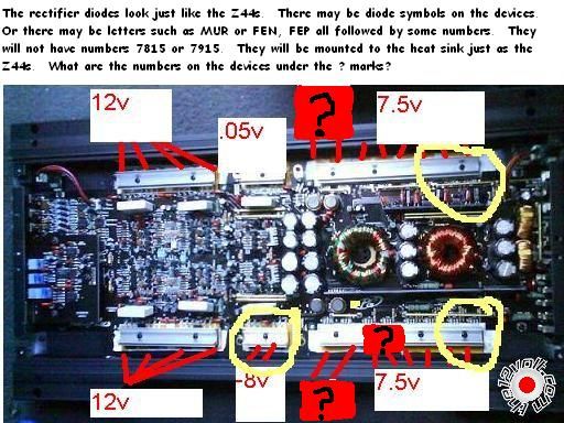
Posted By: tommy...
Date Posted: September 20, 2009 at 7:37 AM
That looks almost identical to the Planet Audio i am working on...! Where did you get the z44's from...? Best i found was 20 of them for $20 before shipping...?! I know you told me mouser,digikey idiot...Was just curious...!
-------------
M.E.C.P & First-Class
Go slow and drink lots of water...Procrastinators' Unite...Tomorrow!
Posted By: ianarian
Date Posted: September 20, 2009 at 7:55 AM
Looks like there's four of them, 2 are labeled F1B2CCI-641 and the other 2 are F1B2CAI-639.
-------------
This is what I do for FUN!
Posted By: i am an idiot
Date Posted: September 20, 2009 at 9:28 AM
Those would be them. I have never seen those numbers, but I can assume that the CC is for common cathode and the CA is for common anode. Remove only the 2 on the power supply of the one that is blowing the fuse. And make a note so they go back in the same location. That part is critical. Since you can not cut these legs off, it is safer to apply as much solder as you can to each of the 3 joints on the component. Then lay your iron across all 3 connections and heat them all up at the same time. The tab of the transistor will get too hot to hold, use some small pliers only to keep from burning your fingers. Do not apply much pressure with the pliers, when the joints get hot enough, the part will easily come out of the board.
Once you get the diodes out, clean up the solder joints and make sure none are touching. Power it up with the single 5 amp fuse, check the voltage across power and ground. If the fuse does not blow, there is a problem with the output section. If the fuse still blows, you need to follow the trace from the left ldg of the 44s to the resistor, then out of the resistor to a transistor, what is the number on that transistor. The same trace may go to a second transistor what is the number on that transistor also?
Posted By: ianarian
Date Posted: September 20, 2009 at 12:34 PM
Allied? I think, they are in Washington, oh got receipt here, alliedelec.com I think it was $12 with shipping. For everything. Took forever to get here Fed-Ex ground.
-------------
This is what I do for FUN!
Posted By: ianarian
Date Posted: September 20, 2009 at 1:41 PM
fuse held, 10.41v (which is equal to the battery voltage) and the transistors are A1266, K-620\
-------------
This is what I do for FUN!
Posted By: i am an idiot
Date Posted: September 20, 2009 at 3:14 PM
Read the second paragraph before you take the amp apart to check for bridged solder joints on the bottom of the board. We seem to still have a problem at the output transistors. Check and make sure you do not have a bridged solder joint on one of the outputs you replaced. Check the top and the bottom of the board. Also check to see that you did put them back in the right spot. In order to check this, the middle leg of one of the rectifier diodes will show a dead short between the middle or the right leg of the outputs. The CA diode will be connected to one and the CC will be connected to the other. You may have to pull the clamps off of the 4 channel part and verify which output is connected to which diode. They will be the same on the part of the amp we are working on. Before you do anything else, run the amp for a few minutes to see if the heat sink is heating up on the supply you worked on. Make sure you mount it back into the sink. If there is a problem with the drivers, the 44s will heat up on that side before they heat up on the other side. After you leave it on for a bit and determine that it is not heating up, check for shorted solder joints on the outputs. Also check the resistance of the rectangular concrete looking resistors near the outputs. Now set your meter to the diode test function and check for shorted driver transistors near the outputs you changed. Check all possible combinations of those legs. If you get any readings below .300, check the same transistor on one of the other channels of the amp.
Posted By: ianarian
Date Posted: September 20, 2009 at 4:19 PM
I wanted to run by ya, we still have the tip36 transistors, I am not sure if we need em. They sit next to the heatsink we presumed to be the power supply transistors for the sub(page1). If they're irrelevant then I'll proceed.
-------------
This is what I do for FUN!
Posted By: i am an idiot
Date Posted: September 20, 2009 at 7:38 PM
After you test for heat with the diodes still removed, at least remove the 36s, they may be leaking, Since you have them I would replace them. They are rated at the same current as the 35s, they went through the same abuse as the 35s, they may have survived but could be weak.
Posted By: ianarian
Date Posted: November 19, 2009 at 10:11 PM
OK, I just got it all put back together, tip36's changed, and powered it up with all 5a fuses and they all held. So now, I got the proper size fuses in and I'm wondering if that means it's ok to give it a run.
-------------
This is what I do for FUN!
Posted By: i am an idiot
Date Posted: November 20, 2009 at 12:21 AM
We are getting close. But just to be safe, power it back up and leave it on for about 5 minutes. You need to monitor the heat sink the entire time to see if it is getting warm. No Speaker wires and no RCA jacks. After 5 mnutes you should begin to feel it warming slightly. If it is getting hot you may want to stop. If it is only getting a few degrees above ambient, connect speaker wires and RCA cables and try playing it. With the 5 amp fuses, it will only play at a very low volume, turn it up until you can barely hear any audio. Walk areound the vehicle listening carefully to each speaker. If they all sound free of distortion, gradually turn the volume up until you blow the fuses. If all sounded good until the fuse blew, Cross your fingers and insert the proper size fuses. Play it again and see what happens.
Posted By: ianarian
Date Posted: September 19, 2010 at 7:28 AM
Well the thing lasted through the summer. It never got real hot on the lake though. I got it in a bass boat and the owner listens to country, he appreciates the amp tremendously. So thanks for the 7 pages of H311. I'd like to believe that it was time well spent on both our behalves. YOU'RE the man, Idiot!
-------------
This is what I do for FUN!
Posted By: i am an idiot
Date Posted: September 19, 2010 at 9:39 AM
Glad to be able to help you. Thanks for reporting back.
|