diode protected relay
Printed From: the12volt.com
Forum Name: Car Audio
Forum Discription: Car Stereos, Amplifiers, Crossovers, Processors, Speakers, Subwoofers, etc.
URL: https://www.the12volt.com/installbay/forum_posts.asp?tid=119393
Printed Date: April 18, 2026 at 6:22 AM
Topic: diode protected relay
Posted By: y2j514
Subject: diode protected relay
Date Posted: January 16, 2010 at 5:56 PM
Ok so I want to use a relay on my remote wire from my HU to turn on my amplifiers and a few fans. I want to diode protect the relay to avoid the voltage spike that happens with the instant flicking of the coil.
I know you must place the diode across the relay with the cathode (striped side) facing the positive side of the coil. I am just wondering what rating of a diode I need?
I have a 15 volt 1/2 Watt diode lying around - any good?
Thanks
Replies:
Posted By: i am an idiot
Date Posted: January 16, 2010 at 6:13 PM
Do not use a Zener diode. With the rating you gave, that appears to be a Zener. You need a 1N400X, where X is any number from 1 to 7
Posted By: y2j514
Date Posted: January 16, 2010 at 6:17 PM
You're absolutely right. It is a Zener diode. Thanks for the input. If you don't mind, otherwise I can just google it, what exactly is the difference between these 2 diodes?
Posted By: i am an idiot
Date Posted: January 16, 2010 at 6:29 PM
Description of diode at the top of the following page. Zener diode description about 1/3 way down the page. https://www.bcae1.com/diodes.htm
Posted By: y2j514
Date Posted: January 16, 2010 at 6:45 PM
Thank you. So since I have to go out and buy a diode - do you recommend one more than the other? In terms of X being 1 to 7.
Posted By: i am an idiot
Date Posted: January 16, 2010 at 7:05 PM
The 4001 is rated at 50 volts, the others are rated at higher voltages. For automotive applications none will be any better than the other. Whatever you can find will work.
Posted By: oldspark
Date Posted: January 17, 2010 at 2:51 AM
The 1N4004 (400V) seems to be the most common with 4007 (1000V) close by - the others seem to have bee dropped (at least here under).
Usually 200V or higher is chosen for automotive applications...
Posted By: y2j514
Date Posted: January 17, 2010 at 2:46 PM
Ok, so I've been doing some reading around and I'm worried that the fans will make too much noise when I play the music at a quieter level.
I know using a thermisistor is possible - although even using bcae1 I have no idea how to do it. I can follow the logic pretty well - I just cant 100% read the diagram on bcae1.
I doubt this is an option but is there a way to simply make the fans spin faster as the volume increases? Like using an splicing an RCA cable from the HU or something?
Posted By: i am an idiot
Date Posted: January 17, 2010 at 7:14 PM
The wire labeled to active speaker terminal connects to a bridged speaker wire of a multichannel amp, or the positive terminal of a mono amp. https://www.bcae1.com/temp/speakerlevelfancontroller01.gif Save the image to your harddrive. I have no idea how long it will stay on his server.
Posted By: i am an idiot
Date Posted: January 17, 2010 at 7:16 PM
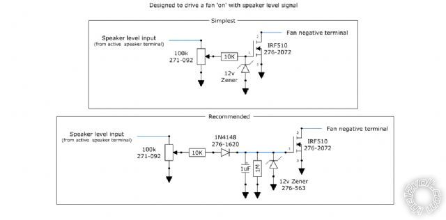
All parts are available at Radio Shack. The 6 or 7 digit numbers are radio shack part numbers. The resistors are 1/4 watt or 1/2 watt. whatever they have in stock. The cap should be 16 volts or higher.
Posted By: y2j514
Date Posted: January 17, 2010 at 7:36 PM
Wow thanks - thats pretty cool. Only problem is I'm having some trouble reading that. I got the jist of it though. See the problem is I'm no engineer. I am however, very sciency inclined, but the extend of my physics is at a CEGEP level (CEGEP is like the quebec equivalent of the last year of high school/1st year of university). So I know resistors, capacitors etc. the basic. If I were to go about this - should I do this on a small perforated board? Finally, would I have to do one of these circuit for each fan or could I connect the fans in series at the end of this one circuit?
Posted By: i am an idiot
Date Posted: January 17, 2010 at 7:50 PM
The device far left of the bottom diagram is a 100K potentiometer. There are 3 connections on it. The middle one connects to the 10K resistor. If you get the stuff from Rad Shack, let me know I can draw you an actual picture so you know which terminal of the pot connects to input or ground. Also the transistor has 3 legs on it also. The fans must be connected in parallel. You may want to purchase a small heat sink for the transistor if you are going to be pulling more than 1/2 amp through it.
Posted By: oldspark
Date Posted: January 17, 2010 at 8:01 PM
Temp switching may be easy using klixons (is that a trade-name.... ooops?) especially if rounded temps are suitable - ie, here we have 50 60, 70, 80 90, 100, 110 etc degrees-C klixons (about AUD$4-$5 each).
Klixons are merely a 2-terminal thermal switch capable of switching 5A.
They come in NO or NC (Normally Open or Closed) variants.
You'd probably use NO types so they close when above a certain temp.
You could (eg) have one for t-degrees for a "warm" fan, and another at (t+10) degrees as a "hot" fan. It might be one fan with "warm" = slower (series resistor), or 2 fans. (2 klixons with 2 fans is good for redundancy. And the higher temp klixon could be diode connected to the lower temp fan in case the low-temp klixon fails etc.)
If the fan is around or above 5A, a relay is required.
There are other low-current temp devices (thermistors), but they may need a relay to supply adequate load current.
Posted By: y2j514
Date Posted: January 19, 2010 at 8:42 PM
I have a day off on thursday, so I'll try to get supplies then. I like the idea of the fans going with speaker volume.
So fans in parallel with their negative leads connecting to the transistor. Their positive ends I assume connect to any 12v source?
Everything seems pretty straight forward, but just to clarify:
1M (to the right of the 1uf cap) is a... resistor? Finally, all the black arrows are grounds, correct?
Posted By: i am an idiot
Date Posted: January 19, 2010 at 10:42 PM
1M = 1 Megaohm resistor. Yes all black arrows are ground. The transistor connections are numbered. With the transistor positioned where the writing is oriented where you can read the writing, left leg is 1, Middle leg is 2, and the right leg is 3. The potentiometer has 3 connections, with the shaft facing you, and the connections on the top side of the pot. Left connection goes to the speaker wire of the amp. Middle leg connects to the 10K resistor. The right connection connects to ground.
|