how to make a voltage divider
Printed From: the12volt.com
Forum Name: Car Audio
Forum Discription: Car Stereos, Amplifiers, Crossovers, Processors, Speakers, Subwoofers, etc.
URL: https://www.the12volt.com/installbay/forum_posts.asp?tid=120474
Printed Date: March 17, 2026 at 4:34 AM
Topic: how to make a voltage divider
Posted By: cabron19
Subject: how to make a voltage divider
Date Posted: March 03, 2010 at 1:49 AM
Can anyone please tell me how I can make a simple voltage divider?
Apparently I will be needing a 10:1 and a 20:1 divider.
A step by step explanation of the process would be so appreciated!
I am proficient with a soldering iron and working with most through hole components so I am fairly sure I can build the damn thing if I just knew how. 
Thank you in advance for any help.
Replies:
Posted By: anonymous1
Date Posted: March 03, 2010 at 2:05 AM
If you don't mind . . . Is this for DC or AC? What voltage are you stepping down from > to? Do you know what the current draw will be? There are probably some IC or Voltage Regulator solutions readily available. On the whole, what is it that you want to accomplish? .
Posted By: oldspark
Date Posted: March 03, 2010 at 2:34 AM
AC or DC?  (I'm assuming this is NOT for 120V AC etc, but some SAFE voltage!)
If so, see https://en.wikipedia.org/wiki/Voltage_divider.
Then find the current from V=IR => I=V/R
Then each resistor's power from P=VI & V=IR => P=IIR (ie, I x I x R).
All units are volts, amps, ohms & watts.
Else volts, mA, k-Ohms & mW.
Posted By: cabron19
Date Posted: March 03, 2010 at 3:38 AM
here is a link to what I am trying to do.
https://www.diymobileaudio.com/forum/diyma-tutorials/51435-setting-gains-w-o-oscilloscope.html
Posted By: oldspark
Date Posted: March 03, 2010 at 4:09 AM
So would this device work.....?
Posted By: cabron19
Date Posted: March 03, 2010 at 4:15 AM
as in one resister? smarta**
j/k. 
But seriously I can accomplish what I want to do with one friggin resister?
Posted By: oldspark
Date Posted: March 03, 2010 at 5:09 AM
A potentiometer is a variable resistor is a voltage divider.
What impedance (resistance) do you need? Or what is the circuit's input/output impedance.
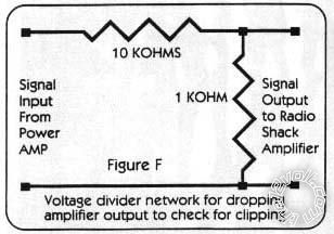
EG - if it's 10kR (10 k-Ohm = 10,000 Ohm) and you need 10:1 out, you could have two resistors: 9kR on top, 1kR on the bottom.
Or you could have a 10k pot (potentiometer; and linear!) dialed at 10% of it's sweep.
A pot is aka a volume control.
In the above diagram, the (say) 10V input is connected to gnd (bottom) and the top resistor (ie, from the left).
The 1V output is take from gnd (bottom) and the center-tap - ie, the bottom resistor out to the right...
Posted By: cabron19
Date Posted: March 03, 2010 at 5:25 AM
Actually I think I finally found what I was looking for:
Posted By: oldspark
Date Posted: March 03, 2010 at 6:29 AM
But you said 10:1 - not 11:1? 
Funny though - otherwise it looks so similar to everything above.
Maybe that's just me..... Maybe you were right, I am smart...
Remember to crank the amp up.
And use 1/2W resistors, they can be more stable.
And will last twice as long as 1/4W resistors in this case. 
|