I'm not sure if anyone else has had this problem, but on old amplifiers I have had problems with stripped screws or even just old/corroded terminal tabs. So what I have done several is disassemble the amplifiers. When I have access to the main board, I de-solder the 12V+, GND, and REM tabs from the board. After this, I take a length of 8 AWG wire, strip the ends off, and solder them in the place of where the old terminals were. Then I use a smaller gauge wire for the REM.
Just like on laptops, where the DC input is soldered directly to the board, these solder tab connections can sometimes crack breaking the circuit. I have done this to two amplifiers and I have been very happy with them since. The first time I did it was because the solder connection cracked and would have needed to be re-soldered regardless in order to keep the amp in use.
Yesterday, I did it to my second amp because when taking the screw off for the GND terminal, I stripped the threads. I spent about 20 mins trying to get it back in and then realized that I could try to do my direct wire thing again.
I disassembled my old amplifier and de-soldered my terminals from the board. I hooked up the 8 gauge wire and soldered it through and then on to the main board in the old spots. I have about 5 feet of power and ground wire hooked up that way if I ever use this amp in a car set up again, I can trim the wire as needed to reach ground or either distribution block. I use distribution blocks in all of my installs weather or not there is only one wire being used since you can get them fused for extra protection and easily add more equipment without having to run to the store or wait for a new distribution block come in the mail.
The REM wire is about 6 inches long with a Male Bullet Crimp so that a switched power source can be easily connected and disconnected. I chose male since when it is disconnected, there would not be a charge and nothing would happen if it accidentally touched ground. Also, it requires the positive switch wire to be a female bullet which prevents it from shorting out on a ground source since it is protected. I love these bullet connectors. I ordered hundreds of them online. I like them more than the spade shaped quick disconnects since you can twist them to disconnect which gives you more leverage and makes it easier.
Please check out the pictures I provided. Anyone who has any feedback let me know.
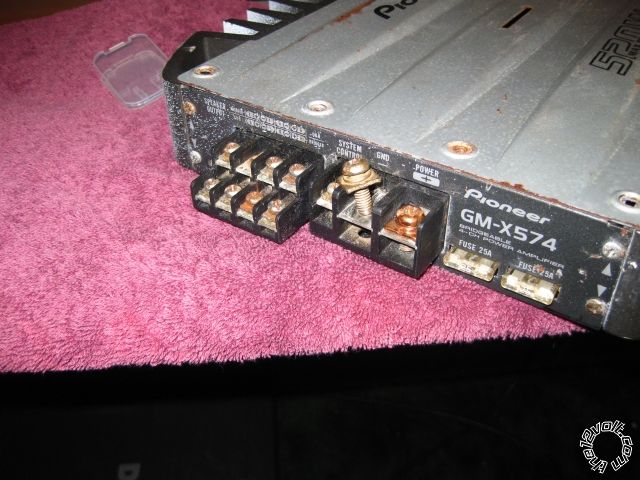
these are the original terminals
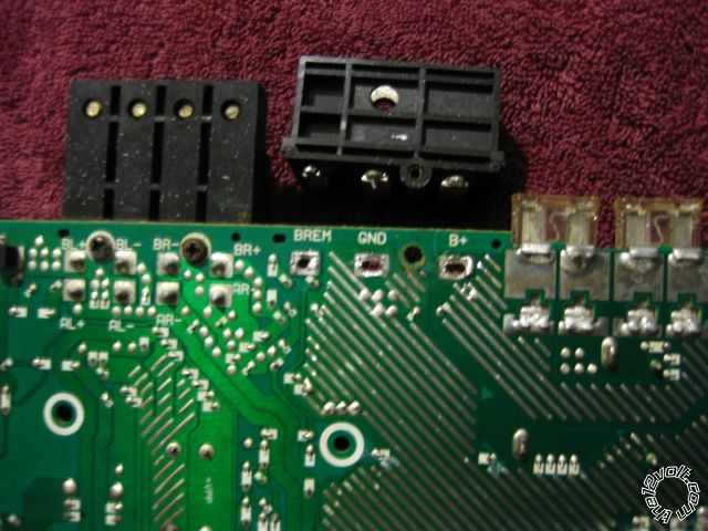
This is the old terminal block desoldered and removed from the board
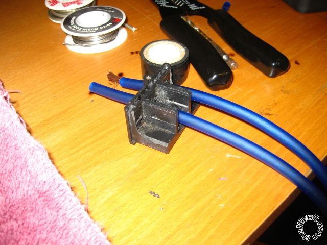
I then drilled holes through the plastic terminal block and ran the 8 gauge wire through new holes
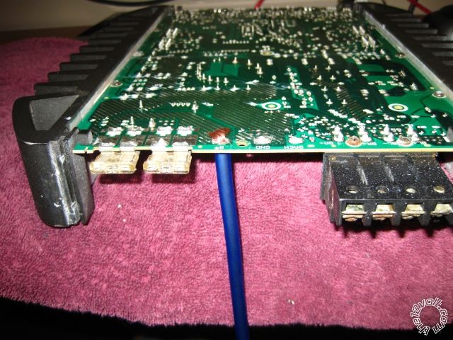
This is the wire on the board
I will included the rest of the pictures in the next post.
Here are the next set of pictures


These are the BAT wire and then all three new wires soldered to the board


This is the view of the 3 wires soldered from the top of the board.
After this I reassembled the amplifier and hooked it up to a car battery in my room. It is louder than my old Mitsubishi home theater receiver

By the way, the amp is a Pioneer GM-X574
Let me know what you think!
Thanks
Tyler