kenwood dnx6140 usb pinout needed
Printed From: the12volt.com
Forum Name: Car Audio
Forum Discription: Car Stereos, Amplifiers, Crossovers, Processors, Speakers, Subwoofers, etc.
URL: https://www.the12volt.com/installbay/forum_posts.asp?tid=124735
Printed Date: May 14, 2026 at 12:29 PM
Topic: kenwood dnx6140 usb pinout needed
Posted By: larry9901
Subject: kenwood dnx6140 usb pinout needed
Date Posted: November 29, 2010 at 7:53 PM
Hello,
I'm needeing some tech info. Possibly a schematic.
I've called just about everywhere I thought of but noone is willing to help me or give me the info I am looking for.
Upon removing my dnx6140 to install it in another vehicle I accidentally ripped the usb cord from my unit. I don't want to have to send it back, I would like to wire a new one in. I am not afraid to solder if needed also as I am very good at doing these tedious things.
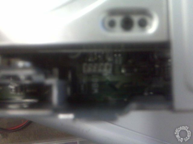
What I need to know is what order do the 5 pins from the female end connect to on a standard 4 pin male usb plug? There are 5 pins on the board on the radio. ( I do know for sure that the male end is a 4 pin usb) Just not sure how to reconnect it beacuse there are 5 pins on the radio.
I did check the pins with a multimeter and found the furthest one to the left is 5volts. None of the others reads voltage.
please see pic below. What is the fifth one for?
Again a schematic would be nice.
Thanks in advance for any help. I hope this post is clear with what I am looking for. and sorry if I am repeating myself.
Replies:
Posted By: haemphyst
Date Posted: November 30, 2010 at 10:32 AM
There won't be voltage on the other pins. The 5VDC is to power the device connected to the cable. One will be ground, and the remaining two will be data paths.
Do you still have the old cable with the header? You should be able to figure it out with that piece.
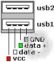
Worst case scenario: As long as you know the ground and +5V for certain, and there is no voltage on ANY of the remaining pins, simply connect the ground and +5V to the known pins on your replacement USB cable. There will be a black (ground), red (+5V), white and green wire inside the USB cable bundle. The remaining data pins/devices will most likely NOT be damaged in either the device or the deck if you have to "shuffle" them... It simply wouldn't work. I've connected the data wires backwards on motherboards, and there has never been any issues. i am an idiot may have some input on this, but *I* personally have never seen any ill-effects from connecting the data wires backwards. Just reverse them, and off you go.
Heres a pic:
Posted By: Ween
Date Posted: November 30, 2010 at 1:58 PM
hi,
or order a replacement cable from pacparts ,they do show an available piece for around $15 minus shipping.
mark
Posted By: larry9901
Date Posted: November 30, 2010 at 2:28 PM
No, I dont have the original.
My dumb a** threw it away assuming I could just purchase a new one from the local audio shop.
Thanks for the diagram above. But it doesnt make sense. The pinout on the host has 5 pins.
Also, how do I determine which pin is ground? The only pin I know for sure is the power as I put a multimeter to it.
Larry
Posted By: larry9901
Date Posted: November 30, 2010 at 3:57 PM
Well, I have another update.
I did end up calling and ordering from Pacparts. Thank-You for the lead.
The sales assistant did verify that there are 5 wires in the usb that has to be hardwired into the motherboard.
There is a red,white,green, and two blacks.
My question now is. How do I determine where the green, white, and two blacks go on the board?
Thanks guys,
Larry
Posted By: Ween
Date Posted: November 30, 2010 at 4:08 PM
i'm thinking the cable maybe terminated with a five pin header, which should insert right into the circuit board after anything existing is removed. you'll have to disassmble to get to the underside (solder) or the main circuit board. your pic shows a tan/milky white plastic piece with terminals inserted in it. also thinking the fifth wire maybe a shield for the USB cable. switch your multimeter on ohms or continuity, place the negative lead to the chassis/metal of the radio. now touch the positive lead to the each of the five terminals. since you already determined one is +5 volts, that leaves the four. see if two of them have continuity to the chassis, those would be your Gnd and shield.
Posted By: larry9901
Date Posted: November 30, 2010 at 4:34 PM
Ween]
wrote:
i'm thinking the cable maybe terminated with a five pin header, which should insert right into the circuit board after anything existing is removed. you'll have to disassmble to get to the underside (solder) or the main circuit board. your pic shows a tan/milky white plastic piece with terminals inserted in it. also thinking the fifth wire maybe a shield for the USB cable. switch your multimeter on ohms or continuity, place the negative lead to the chassis/metal of the radio. now touch the positive lead to the each of the five terminals. since you already determined one is +5 volts, that leaves the four. see if two of them have continuity to the chassis, those would be your Gnd and shield.
Great info!
I will test with multimeter as soon as I receive new cable. The radio is re-installed and I will remove it again upon receipt.
That leads me to another question.
Once I determine the ground and shield. How do I know which one is which on the radio?
Also, on the replacement usb cable, how do I determine which one is ground and which one is shield?
And does it matter if ground is hooked to shield, or shield is hooked to ground?
thanks again,
larry
Posted By: Ween
Date Posted: November 30, 2010 at 6:18 PM
when you get the radio apart, snap a pic of the solder side of the board. post pic, we should be able to help more at that point. there should be points on the circuit board that attach to the radio chassis. follow the circuit board traces at the usb cable connection point and see if any of them connect to that point. could be a bit of a maze, but i can't say for sure.
|