board diagrams?
Printed From: the12volt.com
Forum Name: Car Audio
Forum Discription: Car Stereos, Amplifiers, Crossovers, Processors, Speakers, Subwoofers, etc.
URL: https://www.the12volt.com/installbay/forum_posts.asp?tid=127282
Printed Date: May 16, 2026 at 3:24 AM
Topic: board diagrams?
Posted By: b00nd0ck xs41nt
Subject: board diagrams?
Date Posted: May 10, 2011 at 1:16 AM
Hey all, I have acquired a RF Punch 500a2 amp, and I fried it (no inline fuse) trying to see if it worked. Well, I fried two transistors, and can't find a board diagram anywhere to help me. The diagram I'm needing is for a G500a2.
I also need to find a supplier for the transistors I fried. On the board they are labeled as 'Q19' and 'Q20'. I'd like to get the amp running, because from what I've heard, it's a pretty decent amp for what it is. Thanks in advance!
J
-------------
DJ Jack Ripper, Car audio noob (sort of)
Replies:
Posted By: KPierson
Date Posted: May 10, 2011 at 6:02 AM
Simply hooking up the amp with no fuse will not damage the amp.
-------------
Kevin Pierson
Posted By: i am an idiot
Date Posted: May 10, 2011 at 7:31 AM
Rockford will supply schematics for any out of production piece. I will try to get an e-mail address for you to send a request.
Posted By: b00nd0ck xs41nt
Date Posted: May 10, 2011 at 9:36 AM
KPierson wrote:
Simply hooking up the amp with no fuse will not damage the amp.
It looks like it caught fire on the two transistors, I have pictures, but don't know if they allow img code on here. ------------- DJ Jack Ripper, Car audio noob (sort of)
Posted By: oldspark
Date Posted: May 10, 2011 at 5:20 PM
I case its unclear, Kevin means that NOT having the fuse does not change the circuit/power and hence won;t cause the amp to blow - ie, there is another fault that cause it to blow.
The fuse might have prevented it blowing - but that is another issue.
Posted By: i am an idiot
Date Posted: May 10, 2011 at 7:09 PM
I think I did better than an e-mail address. I did not look for your amp, but it should be here.
https://194.204.29.93/rockford/techlib/products.html
Posted By: i am an idiot
Date Posted: May 10, 2011 at 7:11 PM
Posted By: i am an idiot
Date Posted: May 10, 2011 at 7:28 PM
If you do not have to remove any clamps to see the numbers on the transistors, DO NOT rip the transistors off of the thermal strip. You must use a 100 watt soldering iron or a small torch to heat them up to melt the solder that adheres them to the strip. If you rip them off with pliers, you will destroy the strip.
Posted By: b00nd0ck xs41nt
Date Posted: May 11, 2011 at 12:23 AM
You guys rock. Thanks so much for the help!! Anyone got an idea or two about what have popped the two transistors? I'm accepting all ideas, because this amp could be more beneficial to me than the POS xplod amp I am currently running on my two Pyle 12's. (Yes I know, Pyle = Cheap) I'm looking for somewhat moderate SPL and this is all I can afford at the moment. Again, thank you so much for the link. I have certification in automotive electrical diag and repair, so this schematic is going to help me a LOT.
Instead of starting a new topic, I would also like to ask a question about a JVC EXAD Arsenal KD-AR5500. A local brought it to me, said he couldn't get it to illuminate. I am guessing it is something in the harness, but when he brought it to me, the harness itself wasn't completely clipped into the back of the unit. Going to check it later, and if I get it to work, then good. I like the way it looks and hopefully it'll fit one of my cars well.
-------------
DJ Jack Ripper, Car audio noob (sort of)
Posted By: i am an idiot
Date Posted: May 11, 2011 at 1:54 AM
If the transistor is visibly defective, chances are it is a power supply transistor. The most common cause of this failure is shorted output transistors. The transistors on the other end of the amp.
Posted By: b00nd0ck xs41nt
Date Posted: May 11, 2011 at 10:25 AM
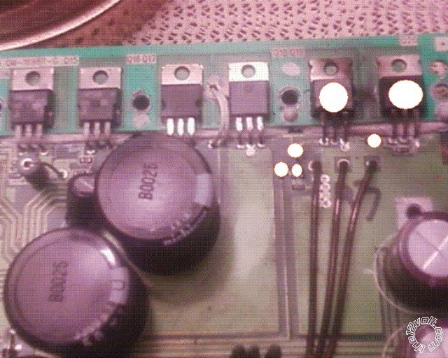
So one thing shorting, could have damaged something else? I have pictures, I'll link them from facebook if that's allowed.


[im]https://a5.sphotos.ak.fbcdn.net/hphotos-ak-ash4/224266_2033622358650_1186915035_2487150_7830444_n.jpg[/img]
------------- DJ Jack Ripper, Car audio noob (sort of)
Posted By: b00nd0ck xs41nt
Date Posted: May 11, 2011 at 10:26 AM

since it didn't work in the last post. ------------- DJ Jack Ripper, Car audio noob (sort of)
Posted By: i am an idiot
Date Posted: May 11, 2011 at 4:54 PM
After you find the shorted output transistors, take a pic of that channel so I can do the same for those parts as I have done for the supply. You only took a picture of the one side of the board. There are 2 transistors on the other side of the amp that also need to be replaced. Every component with the white dot needs to be checked or replaced. What is the resistance of the 2 resistors on this side of the amp? What about the 2 on the other side? Do you know how to check a bi-polar transistor with a digital meter?
Posted By: b00nd0ck xs41nt
Date Posted: May 11, 2011 at 10:27 PM
It's been a while since I've had to do any electrical work, but IIRC, I need to set the MM to Ohms, check resistance on each circuit, and if it's above 1. something, it's bad, or if it has no continuity at all? Sorry, it really has been a while since I've had to bust out my multimeter.
-------------
DJ Jack Ripper, Car audio noob (sort of)
|