pac ms frd1 and 4 channel amp
Printed From: the12volt.com
Forum Name: Car Audio
Forum Discription: Car Stereos, Amplifiers, Crossovers, Processors, Speakers, Subwoofers, etc.
URL: https://www.the12volt.com/installbay/forum_posts.asp?tid=128161
Printed Date: May 16, 2026 at 12:58 AM
Topic: pac ms frd1 and 4 channel amp
Posted By: i am an idiot
Subject: pac ms frd1 and 4 channel amp
Date Posted: August 06, 2011 at 9:35 PM
Pac-Audio.com has been in business since before 1985. That is when I first learned of this company. They made line out converters. This was so long ago that the model number was SNI-8. That is a line out converter for an 8 watt per channel radio. Shortly after that time, high power radios became more and more frequent. They had to add the SNI-15 to their lineup. That is for a 15 watt per channel radio. Point being, they know people install amplifiers into their vehicles.
In January this year we installed a Double Din DVD player into a 2011 F-150 with the Sync system. This piece worked flawlessly. Customer came in yesterday wanting to install a 4 channel amp and upgrade his door speakers. The installer is giving me trouble telling me that the module is not going to work with an amplifier. My argument was, dude, they have been making LOCs for over 25 years, they know people are putting amps in their cars. The module will handle the power of an amp. Guess who the idiot was. Yup it was me. We did get it in and working. Took some work, but we made it happen. Pac tech support was freaking out when I told them we ran an amp on the unit,
All was fine at low to medium volume. Problem was at high volume with all 4 channels driven, the module would power the radio down. That is how it kills rear speakers to answer a bluetooth call. 2 channels at a time would work much better, amp had to reach clipping before unit would shut down. Thought this was going to be an easy fix, bypass the box with the rear speakers. Front has to run through it in order for the bluetooth to work. That did not help much. My customers Love them some clipping. It was still shutting down.
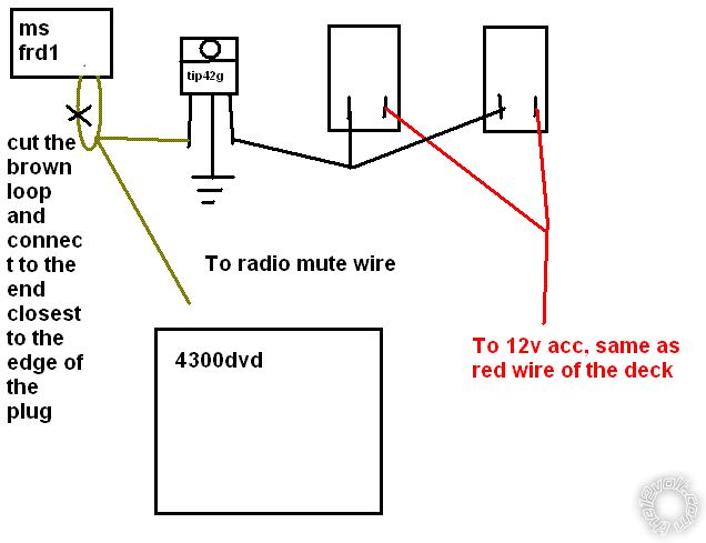
Pac tech support did tell me about the brown loop. If you cut that loop, and connect the radio's mute wire to the brown loop wire that is closest to the end of the plug, this will mute the radio instead of killing power. It would mute the radio when the volume was turned up, this was much better than having the deck power down and have to wait for it to come back up.
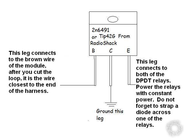
What was done to fix the problem: I had to use a transistor and 2 DPDT relays from Radio Shack to completely bypass the module with all amp wiring. I will post diagram for the transistor. Transistor is triggered by the brown wire of the pac module. Same wire that mutes the deck.
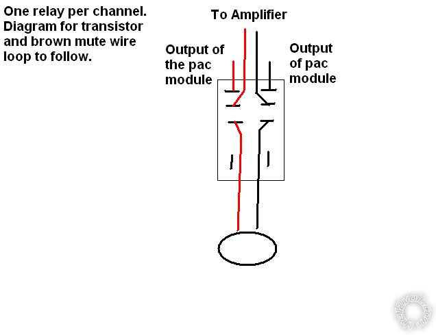
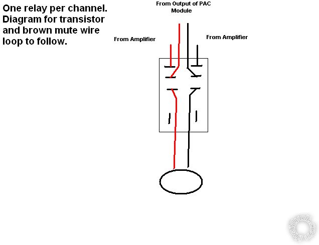
Relays wired as follows: Common terminals to speaker wires. Only front channels need to go through relays. Rear channels can not go through the module, just wire the rear speakers directly to the amplifier.
Normally closed contacts to the output of the amplifier.
Normally open contacts to the output of the module. This is only needed for bluetooth phone operation.
So don't go thinking that Pac knows you are going to amplify your systen, and make their interface modules accordingly. If you think that you may look like you have no clue. Like me.
Replies:
Posted By: i am an idiot
Date Posted: August 06, 2011 at 9:46 PM
Posted By: i am an idiot
Date Posted: September 29, 2011 at 3:39 PM
If using Bosch/Now Tyco relays. 30 is the common terminal. this connection goes to the speakers. 87A is the normally closed connection, this is to be connected to the aftermarket amplifier. 87 is the normally open connection, this connects to the output wires of the above mentioned Pac integration harness.
If using these relays, it will take a total of 4 relays. 2 for the left speaker and 2 for the right speaker. One relay for the positive wire, and one for the negative wire.
If you do use a DPDT relay, post a picture of the connetions of that relay and I can give more guidance.
Posted By: rocketpod23
Date Posted: September 30, 2011 at 4:03 AM
Currently trying this with a 2010 f150. I have a Pioneer AVH P4300 HU, with the PAC MSFRD1 Sync adapter, and will be trying to run a Rockford Fosgate 4 channel amplifier to my Pioneer 3 way door speakers.
I've searched the net, and talked to a lot of tech support, in an attempt to make this work without sacrificing any of my vehicle's Sync capabilities. If this works, I will definitely give feedback. I know I can't be the only one looking to do this. It may time a couple of weeks to get all this together, but I will certainly post results.
Posted By: i am an idiot
Date Posted: September 30, 2011 at 10:57 AM
It does work just as you desire. It has been in the truck since a week before I initially posted. Same exact head unit in a 2011 truck.
Transistor part number is 276-2027
Relay part number is 275-216 you will need 2 of these. Relays 10 bucks each, transistor less than 2 dollars. You will need some solder and a soldering iron if you do not already have one. If you have to purchase an iron, do not waste your money on a Radio Shack iron. Spend a few extra dollars and get a Weller iron.
Posted By: i am an idiot
Date Posted: October 01, 2011 at 11:03 PM
\If you have not went to Radio Shack yet, pick up a diode while there. 276-1101 or 276-1102 or 1103
Posted By: i am an idiot
Date Posted: October 02, 2011 at 6:31 PM
I did not get a layout of the relay from Radio Shack. They did have a picture, from what I could see through the smoked plexiglass cover, this should be accurate. Check against this info before wiring it up. Top set of contacts should be the NC (Normally Closed) contacts. Just below that is the NO contacts. Then the Common contacts. Coil connections are at the bottom of the relay.
Posted By: i am an idiot
Date Posted: October 02, 2011 at 7:09 PM
I forgot to draw the diode on the diagram. It needs to go across the coil of one of the relays. The end of the diode that has the band on it MUST be connected to the terminal that has positive voltage. The transistor does not need a heat sink. The tab of the transistor is connected to the middle leg. There is ground on the tab. If you want to mount it to a bracket or directly to the chassis, that will be fine.
Posted By: i am an idiot
Date Posted: October 03, 2011 at 8:33 PM
I looked at the pictures you sent. The above diagrams are exactly what you need.
Did you buy the exact part number relay I suggested? They sell a 3 amp and a 10 amp device. The pic looks like it may be smaller in size than the ones I have used. if it is the 3 amp unit, I have no idea how long it will last.
Posted By: rocketpod23
Date Posted: October 04, 2011 at 10:40 AM
grr, the relays I got are Part Number- 275-0218. I picked them up before your post listing the specific PN. I wander if they are the same. Judging from the new diagrams you posted, and the diagram on the package of the relay, they seem to be the same.
Posted By: i am an idiot
Date Posted: October 04, 2011 at 8:54 PM
You have the correct relays.
Posted By: rocketpod23
Date Posted: October 09, 2011 at 10:56 PM
Posted By: rocketpod23
Date Posted: October 10, 2011 at 3:33 AM
Made this last night. May have to do a couple of tweaks yet, but for the most part it should be ready to go. Still waiting on my amplifier, and amp kit to come in the mail. Next challenge is to drill holes in my front door molex connectors. I will update as progress is made.
Posted By: i am an idiot
Date Posted: October 10, 2011 at 5:32 AM
How big of an amplifier are you using? If it is under 200 watts per channel, you will never hear the benefits of upgrading your speaker wire.
Place a couple ty-wraps an inch or so below the end of the heat shrink of the transistor. Tighten them enough to keep the wires from twisting. The legs of the transistor do not like being flexed.
Posted By: i am an idiot
Date Posted: October 13, 2011 at 8:59 PM
You are correct about my picture being inaccurate. The markings, to amplifier and from pac module are pointing to the wrong terminals. I will redraw the pic and see about getting the other one deleted.
Posted By: rocketpod23
Date Posted: October 14, 2011 at 11:40 AM
Awesome. Thanks for the info, and the quick replies.
Posted By: rocketpod23
Date Posted: October 20, 2011 at 5:15 PM
Just saying thanks again for all your help. Everything works exactly the way I wanted! I actually can't wait to drive to work in the morning to hear the new sound (as depraved as that is).
Posted By: i am an idiot
Date Posted: October 22, 2011 at 7:40 PM
I finally got around to correcting the picture. I am glad you caught the mistake before you built it. The picture was labeled wrong. Verbal instructions were accurate. I would love for a moderator to delete this post and replace the earlier pic with this one. Thanks in advance.
Posted By: Cali_pilot
Date Posted: February 26, 2012 at 4:02 AM
OK, so I just undertook this installation on my 2011 F-150 w/Sync. When I was planning the install, I thought I was basically going to hook up my amplified speaker outputs directly into the MS-FRD1 speaker inputs instead of using my Pioneer head unit's speaker outputs. I did exactly that and almost everything was gravy. Music played out of my speakers and the voice commands/phone calls played through the front speakers, as planned. The only issue was that I was having a buzzing/distorted sound out of my speakers but only when I was using Sync. If I was listening to FM, or the on-board HDD, everything was fine but as soon as I switched to Sync and used USB, Line-in, or Bluetooth Audio, the buzzing played through the speakers along with the music.
After several phone calls with PAC, they decided that my issue was the input I was using on my head unit to play the Sync audio. My head unit has the IP-BUS input but I don't have the adapter for it so I just used the A/V inputs. I've used them in the past for connecting an RCA to 3.5mm cable for my iPod and it always worked fine. I explained to them that if I go directly from my iPod to the A/V input everything sounds great but they said that the PAC RCA output signal was too strong for my A/V input and was causing the distortion I was describing. I even went directly from the PAC to my amp since I know my amp can handle 8v inputs and the distortion was still there. I ended up having to have another PAC shipped out to me. Still waiting on it to arrive. They did at one point ask me how my setup was installed and they freaked out when I told them I was going straight from my amp to the speaker inputs on the PAC. They swore that if I continued with my current connections, the PAC would eventually fry because it wasn't meant to handle more than the typical 50W max per channel that the average head unit can output. I was under the impression that under the hood of the PAC, the speaker inputs were wired directly to the speaker outputs without going through any type of circuit board. I guess I was wrong.
So now I'm having to figure out how to connect my amp to my front speakers while retaining the voice commands/bluetooth sounds that are played through the front speakers driven by the Sync system. I understand the logic behind the recommended setup on this post but I'm wondering if perhaps there is an easier way to go about it. I was thinking of bypassing the PAC and splicing my amp's speaker wires into the front speaker outputs on the PAC harness. My only concern is whether the amp'd signal would affect the Sync system since they both would share the same output wires. I'm not sure if it would send the signal to the Sync and fry the system. I'm not worried about it affecting the speakers in any way because the front speakers would only ever receive a signal from one source at the same time since when voice commands/bluetooth are active, the head unit is muted. I was thinking maybe it would be possible to diode isolate my amp's signal from the speaker output on the PAC so that my amp'd signal would not affect the Sync system. I was thinking I could cut the wires going from the front speaker outputs on the PAC to the vehicle's harness, connect my amp's speaker wires to the vehicles harness, and connect a diode between the front speaker outputs on the PAC and the vehicle harness. But then I don't know if the Sync's output would affect my amp since the signal would make it's way into the amp's outputs. I know my way around installing mobile electronics, I just don't know if this would work without affecting something else. I'm not even sure if it's possible to diode isolate that strong of a signal (80W RMS). Please feel free to make suggestions. If anything, I can always go with the tested method posted earlier.
-------------
2011 Ford F-150 Super-Crew FX4
HU: Pioneer AVIC-Z1
Fronts: Infinity Kappa 682.9cf
Rears: Infinity Kappa 682.9cf
Amp: Profile AP1040
Sub: Pioneer TS-SWX251
Posted By: Cali_pilot
Date Posted: February 26, 2012 at 4:58 AM
Also, using the schematic, could you please draw or explain in better detail where the diode is being installed. I guess I just don't understand what is being isolated. Thanks.
-------------
2011 Ford F-150 Super-Crew FX4
HU: Pioneer AVIC-Z1
Fronts: Infinity Kappa 682.9cf
Rears: Infinity Kappa 682.9cf
Amp: Profile AP1040
Sub: Pioneer TS-SWX251
Posted By: i am an idiot
Date Posted: February 26, 2012 at 8:29 AM
https://www.the12volt.com/relays/page5.asp
On the above page there are several diagrams with a quenching diode paralleled across the coil of a relay. A diode is a polarity sensitive device. You need to put it across only one of the relays.
Use the last diagram I posted for the relays. The other guy pointed out that I had the 2 inputs reversed in the first diagram.
I will read your long post later today and then answer any questions you have.
Posted By: i am an idiot
Date Posted: February 26, 2012 at 5:15 PM
The relays are the only way to do what you need done. A diode will not isolate the amp signal from the sync module. A diode in line with an audio signal will not sound good at all.
I too was shocked when PAC tech support told me that I could not run an amp through their module. The very first piece of PAC equipment I ever saw was an SNi-8. A line out converter for an 8 watt radio. They got their start interfacing OEM radios to aftermarket amplifiers. Why would they make a piece as this that would not allow you to use an amplifier?
|