16 gauge copper wire to small?
Printed From: the12volt.comForum Name: Car Audio
Forum Discription: Car Stereos, Amplifiers, Crossovers, Processors, Speakers, Subwoofers, etc.
URL: https://www.the12volt.com/installbay/forum_posts.asp?tid=38642
Printed Date: May 15, 2026 at 9:49 AM
Topic: 16 gauge copper wire to small?
Posted By: cyberer
Subject: 16 gauge copper wire to small?
Date Posted: September 05, 2004 at 4:24 PM
Replies:
Posted By: Asmodeus
Date Posted: September 05, 2004 at 4:34 PM
I would use something a little thicker...12ga...
16 would be fine for mids and highs something that doesnt have as much current draw...
-------------

Posted By: Ravendarat
Date Posted: September 05, 2004 at 4:39 PM
-------------
double-secret reverse-osmosis speaker-cone-induced high-level interference distortion, Its a killer
Posted By: Teken
Date Posted: September 05, 2004 at 5:58 PM
Then you would be wise to upgrade to a larger guage. As it was indicated by Asmodeus, 12 guage would be better, and it will allow you to increase the draw in the future without any fears.
It really comes down to how you listen to your music, and at what volume levels. Which the amplifier, and sub are also factors.
If you are doing the occasional ground pounding, then 16 guage is just fine. If you listen at extreme levels all day long, and the insulator is of low quality you will find that the cable will fuse do to excessive current draw.
Pay now, or pay later . . . The costs for 12 guage is so cheap, why not??
Regards
EVIL Teken . . .
Posted By: customsuburb
Date Posted: September 05, 2004 at 8:03 PM
Teken] wrote:
6 guage will pass 15 amperes at a continous steady state. If your amplifier / sub combination will draw down more than 15 amperes steady state.
Then you would be wise to upgrade to a larger guage. As it was indicated by Asmodeus, 12 guage would be better, and it will allow you to increase the draw in the future without any fears.
It really comes down to how you listen to your music, and at what volume levels. Which the amplifier, and sub are also factors.
If you are doing the occasional ground pounding, then 16 guage is just fine. If you listen at extreme levels all day long, and the insulator is of low quality you will find that the cable will fuse do to excessive current draw.
Pay now, or pay later . . . The costs for 12 guage is so cheap, why not??
Regards
EVIL Teken . . .
Teken, I think cyberer is talking about the wire going from his speaker output on his amp to his sub, not his power wire.
-------------
Posted By: Steven Kephart
Date Posted: September 05, 2004 at 8:45 PM
My boss told me once that 16 awg is plenty for speaker wire. I proved him right at a competition pulling a very impressive number for my setup and only using 18 awg wire. The output of amplifiers are usually high voltage/low current which is why you can get away with smaller wire. Sure larger wire looks better and will be used in my install in the future, but it isn't needed from a performance standpoint.
Steven Kephart
Adire Audio
-------------
Posted By: Ketel22
Date Posted: September 05, 2004 at 9:55 PM
steven maybe you should bring your older more technical explaination back if there is further dispute about it...
-------------
Quad L Handyman services
Posted By: dpaton
Date Posted: September 05, 2004 at 10:18 PM
Steven Kephart wrote:
ure larger wire looks better and will be used in my install in the future, but it isn't needed from a performance standpoint.
While I don't doubt that Dan is right in some circumstances, dampening factor can have a large effect on the sound and efficency of a system. The cbale ABX tests I've done have shown it irrifutably.
To those who don't know about DF:
Think of it this way...an amplifier has a certain output impedence, usually around 0.01 ohm in car amps. A speaker has a certain impedence, usually 4 ohms nominal. That makes the dampening factor 400 (4/0.01). DF is the measure of how much control the amplifier has over the driver. Any resistance between the amplifier and the driver is counted into the amplifier part of the equiation. If you have 0.5 ohms of wire in between the amp and the speaker (0.25 ohms in each wire...round trip impedence is important), all of a sudden your DF drops from 400 to 7.8 (4/(0.01+0.5)).
Taking the example of a pair of front speakers and an amp in the back of the car (15' of wire is not at all uncommon), 30 feet (remember, it's round trip) of 16AWG wire and a 4 ohm speaker will give you a dampening factor of only 30. 18AWG would give you the same DF with only a 9.8' run. 10AWG is definately overkill, but if you're using long runs, 18AWG isn't the greatest idea either.
Personally, I use 12AWG for my fronts because my amp (an old ADS) has a relatively high output impedence, and I want to do everything I can to help it out.
-dave
-------------
This is not a sig. This is a duck. Quack.
Posted By: stevdart
Date Posted: September 05, 2004 at 11:16 PM
-------------
Build the box so that it performs well in the worst case scenario and, in return, it will reward you at all times.
Posted By: Steven Kephart
Date Posted: September 06, 2004 at 12:38 AM
dpaton wrote:
Steven Kephart wrote:
ure larger wire looks better and will be used in my install in the future, but it isn't needed from a performance standpoint.
While I don't doubt that Dan is right in some circumstances, dampening factor can have a large effect on the sound and efficency of a system. The cbale ABX tests I've done have shown it irrifutably.
To those who don't know about DF:
Think of it this way...an amplifier has a certain output impedence, usually around 0.01 ohm in car amps. A speaker has a certain impedence, usually 4 ohms nominal. That makes the dampening factor 400 (4/0.01). DF is the measure of how much control the amplifier has over the driver. Any resistance between the amplifier and the driver is counted into the amplifier part of the equiation. If you have 0.5 ohms of wire in between the amp and the speaker (0.25 ohms in each wire...round trip impedence is important), all of a sudden your DF drops from 400 to 7.8 (4/(0.01+0.5)).
Taking the example of a pair of front speakers and an amp in the back of the car (15' of wire is not at all uncommon), 30 feet (remember, it's round trip) of 16AWG wire and a 4 ohm speaker will give you a dampening factor of only 30. 18AWG would give you the same DF with only a 9.8' run. 10AWG is definately overkill, but if you're using long runs, 18AWG isn't the greatest idea either.
Personally, I use 12AWG for my fronts because my amp (an old ADS) has a relatively high output impedence, and I want to do everything I can to help it out.
-dave
Interesting, a possible technical dispute. I will have to let Dan know about this thread and see what comes up. I remember a LONG time ago Richard Clark gave a tech answer on why damping factor is a useless rating, but I have seen Dan prove RC wrong in some instances. I'm kinda curious where Dan stands on this issue.
Maybe you could explain how Damping Factor effects the control over the woofer? Remember the speaker produces a dynamic impedance that can change from 4 ohms (we'll use a more standard driver) all the way up to 80 ohms and sometimes beyond (depending on enclosure/speaker/frequency). 18 awg wire 30 feet long has a resistance of .1956 ohms at 77 degrees farenheit. I can't see how such a small change in resistance from going to a larger awg wire would have any effect on the system, especially when the speakers impedance is changing so much. Power loss is VERY small, and completely inaudible.
I'm really looking forward to your answer.
Steven Kephart
Adire Audio
-------------
Posted By: haemphyst
Date Posted: September 06, 2004 at 12:23 PM
DAMPING FACTOR: EFFECTS ON SYSTEM RESPONSE
A TECHNICAL ANALYSIS
Dick Pierce
Professional Audio Development
1 INTRODUCTION
Much ballyhoo surrounds the concept of "damping factor." it's been suggested that it accounts for the alleged "dramatic differences" in sound between tube and solid state amplifiers. The claim is made (and partially cloaked in some physical reality) that a low source resistance aids in controlling the motion of the cone at resonance and elsewhere, for example: "reducing the output impedance of an amplifier and thereby increasing its damping factor will draw more energy from the
loudspeaker driver as it is oscillating under its own inertial power." [1]
This is certainly true, to a point. But many of the claims made, especially for the need for triple-digit damping factors, are not based in any reality, be it theoretical, engineering, or acoustical. This same person even suggested: "a damping factor of 5, ..., GROSSLY changes the time/amplitude envelope of bass notes, for instance. ... the note will start
sluggishly and continue to increase in volume for a considerable amount of time, perhaps a second and a half." Instead of unbridled hyperbole, there have been attempts at a reasoned justification for damping factor. Witness a recent rec.audio.tech post: "Since the amplifier source impedance is indeed much smaller than the speaker impedance, the latter is almost insignificant. In fact, an amplifier with a damping factor of 50 will sink twice the current of one with a damping factor of 25, and therefore dissipate four times the resonant energy." [2] As intuitive as this analysis might seem, it is quite flawed since, as we will see, it simply ignores the one major loss factor in the entire system, throwing it out the window as if the single most important controlling element over cone motion had no real relevance.
2 DAMPING FACTOR: A SUMMARY
What is damping factor? Simply stated, it is the ratio between the nominal load impedance (typically 8 ohms) and the source impedance of the amplifier. Note that all modern amplifiers (with some extremely rare exceptions) are, essentially, voltage sources, whose output impedance is very low. That means their output voltage is independent, over a wide range, of load impedance. Many manufacturers trumpet their high damping factors (some claim figures in the hundreds or thousands) as a
figure of some importance, hinting strongly that those amplifiers with lower damping factors are decidedly inferior as a result. Historically, this started in the late '60's and early '70's with the widespread availability of solid state output stages in amplifiers, where the effects of high plate resistance and output transformer windings traditionally found in tube amplifiers could be avoided. Is damping factor important? Maybe. We'll set out to do an analysis of what effect damping factor has on what most proponents claim is the most significant property: controlling the motion of the speaker where it is at its highest, resonance.
The subject of damping factor and its effects on loudspeaker response is not some black art or magic science, or even excessively complex as to prevent its unserstanding by anyone with a reasonable grasp of high-school level math. It has been exhaustively dealt with by Thiele [3], Small [4] and many others decades ago.
3 SYSTEM Q AND DAMPING FACTOR
The definitive measurement of such motion is a concept called Q. Technically, it is the ratio of the motional impedance to losses at resonance. Another, completely equivalent view is that Q is the ratio between the amount of energy stored in the system vs the energy dissipated by losses. It is a figure of merit that is intimately connected to the response of the system in both the frequency and the time domains. A loud-speaker system's response at cutoff is determined by the system's
total Q, designated Qtc, and represents the total resistive losses in the system.
Two loss components make up Qtc: the combined mechanical and acoustical losses, designated by Qmc, and the electrical losses, designated by Qec. The total Qtc is related to each of these components as follows:
Qmc * Qec
Qtc = --------- [Eqation 1]
Qmc + Qec
Qmc is determined by the losses in the driver suspension, absorption losses in the enclosure, leakage losses, and so on. Qec is determined by the combination of the electrical resistance from the DC resistance of the voice coil winding, lead resistance, crossover components, and amplifier source resistance. Thus, it is the electrical Q, Qec, that is affected by the amplifier source resistance, and thus damping factor. Qec itself is a measure of, simply, the ratio of the energy stored
in the moving system to the energy dissipated electrically by the losses in the system, that is, in the resistances in the system. The energy stored in the moving system, the kinetic energy, is dependent upon the amount of mass and the velocity. In the context of a speaker, the Qe is (from Small[4]):
2 2
Qec = 2 pi Fc Mmc Re / B l [Eqation 2]
where Fc is the resonant frequency of the system, Mmc is the equivalent moving mass of the system, and Re is the DC resistance of the voice coil (and this assumes 0 source impedance or "infinite" damping factor). Further, B represents the magnetic flux density in the gap and l the length of wire in the magnetic field. (We will assume that we are using the same driver for all considerations here, thus, Fc, Mmc B and l remain the same as well.) The effect of source resistance on Qec
is simple and straight-forward. From Small again [4]:
Re + Rs
Qec' = Qec --------- [Eqation 3]
Re
where Qec' is the new electrical Q with the effect of source resistance, Qec is the electrical Q assuming 0 source resistance (infinite damping factor), Re is the voice coil DC resistance, and Rs is the combined source resistance. The factor
Re + Rs
--------- [Eqation 4]
Re
comes from the fact that Re is built into the original derivation for Qec includes Re in it. The correction simply calculates the incremental increase in Qe with the incremental increase in the total electrical resistance. Reconciling [Eq 4] with [Eq 2], we see that:
2 2
Qec = 2 pi Fc Mmc (Re+Rs) / B l [Eqation 6]
Thus it becomes obvious that the electrical Q of the speaker or, more generally, the electrical damping of the speaker, is NOT dependent upon the source resistance Rs alone (as the proponents of damping factor erroneously claim), but on the TOTAL series resistance seen by the driver, including the DC resistance of the voice coil, Re. This mistake, as commonly as it is made, the the fatal flaw in the entire damping factor argument. It's very important at this juncture to note two points. First, in nearly every loudspeaker system, and certainly in every loudspeaker system that has any pretenses of high-fidelity, the majority of the losses are electrical in nature, usually by a factor of 3 to 1 or greater. Secondly, of those electrical losses, the largest part, by far, is the DC resistance of the voice coil. Now, once we know the new Qec' due to non-zero
source resistances, we can then recalculate the total system Q as needed using [Eq 3], above. The effect of the total Q on response at resonance is also fairly straightforward. Again, from Small [4], we find:
4
Qtc
Gh(max) = sqrt(-------------) [Eqation 7]
2
Qtc - 0.25
This is valid for Qtc values greater than 0.707. Below that, the system response is overdamped and there is no response peak. We can also calculated how long it takes for the system to damp itself out under these various conditions. The scope of this article precludes a detailed description of the method, but the figures we'll look at later on are based on both simulations and measurements of real systems, and the resulting decay times are based on well-established principles of the audibility of reverberation times at the frequencies of interest.
4 PRACTICAL EFFECTS OF DAMPING FACTOR ON SYSTEM RESPONSE
With this information in hand, we can now set out to examine what the exact effect of source resistance and damping factor are on real loudspeaker systems. Let's take an example of a closed-box, acoustic suspension system, once that has been optimized for an amplifier with an infinite damping factor. This system, let's say, has a system resonance of 40 Hz and a system Qtc of 0.707 which leads to a maximally flat response with no peak at system resonance. The mechanical Qmc (i.e. the mechanical contributions to system losses and thus damping) of such a system is typically about 3, we'll take that for our model. Rearranging [Eq 1] to derive the electrical Q of the system:
Qtc * Qmc
Qec = --------- [Eqation 8]
Qtc - Qmc
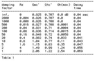
we find that the electrical Q of the system, with an infinite damping factor, is 0.925. The DC resistance of the voice coil is typical at about 6.5 ohms. Let's generate a table that shows the effects of progressively lower damping factors on the system performance:
--------------------------------------------------------
damping Rs Qec' Qtc' Gh(max) Decay
factor time
--------------------------------------------------------
inf. 0 0.925 0.707 0.0 dB 0.04 sec
2000 0.004 0.926 0.707 0.0 0.04
1000 0.008 0.926 0.708 0.0 0.04
500 0.016 0.927 0.708 0.0001 0.04
200 0.04 0.931 0.71 0.0004 0.04
100 0.08 0.936 0.714 0.0015 0.04
50 0.16 0.948 0.72 0.0058 0.04
20 0.4 0.982 0.74 0.033 0.041
10 0.8 1.04 0.77 0.11 0.043
5 1.6 1.15 0.83 0.35 0.047
2 4 1.49 0.99 1.24 0.056
1 8 2.06 1.22 2.54 0.069
--------------------------------------------------------
Table 1
The first column is the damping factor using a nominal 8 ohm load. The second is the effective amplifier source resistance that yields that damping factor. The third column is the resulting Qec' caused by the non-zero source resistance, the fourth is the new total system Qtc' that results. The fifth column is the resulting peak that is the direct result of the loss of damping control because of the non- zero source resistance, and the last column is the decay time to below audibility in
seconds.
5 ANALYSIS
Several things are apparent from this table. First and foremost, any notion of severe overhang or extended "time amplitude" envelopes) resulting from low damping factors simply does not exist. We see, at most, a doubling of decay time (this doubling is true no matter WHAT criteria is selected for decay time). The figure we see here of 70 milliseconds is well over an order of magnitude lower than that suggested by one person, and this represents what I think we all agree is an absolute worst-case scenario of a damping factor of 1. Secondly, the effects of this loss of damping on system frequency response is non-existent in most cases, and minimal in all but the worst case scenario. If we select a criteria that 0.1 dB is the absolute best in terms of the audibility of such a peak (and this is probably overly optimistic by at least a factor of 2 to
5), then the data in the table suggests that ANY damping factor over 10 is going to result in inaudible differences between such a damping factor and one equal to infinity. It's highly doubtful that a response peak of 1/3 dB is going to be identifiable reliably, thus extending the limit another factor of two lower to a damping factor of 5. Further, we simply do not observe the "factor-of-four" increase in energy dissipation with a factor of two reduction in source resistance as claimed in [2]. The statement that it's all about energy dissipation is quite correct: remember that what damping is doing is removing energy from a resonant system, and that the measure of damping is Q, the ratio of energy stored to energy dissipated. Look, for example, at the difference in Qt between a damping factor of 50 and 20: the actual difference in the energy dissipated is less than 3%. According to the theory expounded in [2], the difference in energy dissipation should be around a factor of 6! All this is well and good, but the argument suggesting that these minute changes may be audible suffers from even more fatal flaws. The differences that we see in Q figures up to the point where the damping factor is less than 10 are far less than the variations seen in normal driver-to-driver parameters in single-lot productions. Even those manufacturers who deliberately sort and match drivers are not likely to match a Qt figure to better than 5%, and those numbers will swamp any differences in damping factor greater than 20. It is well known that the performance of drivers and systems is dependent upon temperature, humidity and barometric pressure, and those environmental variables will introduce performance changes on the order of those presented by damping factors of 20 or less. And we have completely ignored the effects presented by the crossover and lead resistances, which will be a constant in any of these figures, and further diminish the effects of non-zero source resistance.
6 CONCLUSIONS
There may be audible differences that are caused by non-zero source resistance. However, this analysis and any mode of measurement and listening demonstrates conclusively that it is not due to the changes in damping the motion of the cone at the point where it's at it's most uncontrolled: system resonances. We have not looked at the frequency-dependent attenuative effects of the source resistance, but that's not what the strident claims are about. Rather, the people advocating the importance of high damping factors must look elsewhere for a culprit: motion control at resonance simply fails utterly to explain the claimed differences.
7 REFERENCES
[1] James Kraft, reply to "Amplifier damping Factor, Another Useless Spec," rec.audio.high-end article
2rcccn$u30@introl.introl.com, 24 May 1994.
[2] Steve (aq433@lafn.org), reply to "How can 2 amps sound so different?," rec.audio.tech article
7go6da$b8q$1@nnrp1.dejanews.com, 04 May 1999.
[3] A. Neville Thiele, "Loudspeakers in Vented Boxes," Proc. IRE Australia, 1961 Aug., reprinted J. Audio
Eng. Soc., 1971 May and June.
[4] Richard H. Small, "Closed-Box Loudspeaker Systems," J. Audio Eng. Soc., Part I: "Analysis," 1972 Dec,
Part II, "Synthesis," 1973 Jan/Feb.
Copyright 1994, 1995, 1998-2001 by Dick Pierce. Permission given for one-time no-charge electronic distribution with
subsequent followups. All other rights reserved.
| Dick Pierce |
| Professional Audio Development |
| 1-781/826-4953 Voice and FAX |
| DPierce@world.std.com |
This document was created with Win2PDF available at https://www.daneprairie.com. The unregistered version of Win2PDF is for evaluation or non-commercial use only.
-------------
It all reminds me of something that Molière once said to Guy de Maupassant at a café in Vienna: "That's nice. You should write it down."
Posted By: haemphyst
Date Posted: September 06, 2004 at 12:27 PM
 )
)-------------
It all reminds me of something that Molière once said to Guy de Maupassant at a café in Vienna: "That's nice. You should write it down."
Posted By: dpaton
Date Posted: September 06, 2004 at 2:00 PM
I'm not saying that Dan is wrong. He's infinitely more knowledgable than I about the intracicies of some things, driver design especially. I do believe, and can support with tests, that wire gauge does have an effect on the sound of a driver. Specifically, I think it has an influence on the relationship between an amplifier's output impedence and the driver's reactance, and a change in the total system Q, which is indeed dependent on the output of the impedence of the amplifier. NB, for the putposes of this discussion, I'm not going to make anyone's brain hurt (including mine) by discussing negative output impedences in amplifiers, mainly because every car amp I've ever seen has had a relatively high (0.01R or so) and definitely positive Zo.
haemphyst posted the Dick Pierce paper I was going to look for, and altho the equations didn't come across totally intact, it's pretty easy to see that the Q of the system becomes progressively less damped as the DF drops.
I disagree with Dick that DF doens't influence the motion of the cone at it's least damped point. As far as his assmption that driver tolerance will swamp DF irregulartities, I've found that many drivers that differ in their specifications, sometimes wildly, will match very nicely when placed into the same box, because the tolerances act to cancel each other. A number of years back, I had a set of 4 Peioneer 10" woofers I wanted to use. I measured the T/S parameters of each very carefully, and came out with Qtc and Qms differences exceeding 40%, but when I loaded the paramaters itno my modelling programs, they agreed that the drivers would perform within 1dB of each other in the exact same box. A change in the porting of less than 5Hz brought them all into a less than 5% window. I've had the same experience with a lot of other drivers, from Vifa mids to Shivas.
I also disagree with Dick that a diffference of 1/3dB is inaudible, when it's been shown coutless times that although it is not perceived as a difference in loudness, a change of volume of 0.3dB is perceived as a definite change in the "sound" of a system, and that when critical AB or ABX tests are performed, matching is required within 0.1dB, preferrably less if possible.
Finally, I honestly believe that the changes in effective Q are the main source of DF complaints. I know for a fact that there is a perceptable difference when changing DF by an order of magnitude (~10 to >100). For Steve's benefit, it was when I moved my dual Dhiva subs from an old Phase Linear 700 II to a Crown K2, both driving the speakers through seperate runs of 6AWG. The first thing my sister noticed was that "the kick drum sounds a lot tighter", which is, as I have found in my years of recording, directly related to the dampening of said drum, either directly or at the reproduction device, AKA the speaker. A high Q (>1) as has been known for a long time, has a typically loose or boomy sound, and does not excel at providing flat frequency reproduction. When combined with the truly wonky way that a small space (a car) influences the behavior of a subwoofer or woofer, things get magnified in a somewhat unpredictable way.
My biggest beef with DF is that people say 18 is fine for a 30' round trip on 4 or 2 ohm drivers that are expected to play loudly. Not only will you lose a very real portion of your power in the wire, but the DF will be so low with a 2 ohm load that the Q will be totally shot to hell.
Comments are welcome for now. I'll post more when I'm not on a working vacation.
-dave
-------------
This is not a sig. This is a duck. Quack.
Posted By: Steven Kephart
Date Posted: September 06, 2004 at 3:17 PM
Wow, thanks for the information guys. I doubt the original poster was expecting this; the complete and complex answer to a simple question. But I hope everyone will read it and learn. I really enjoy these discussions for that reason, no matter who turns out to be wrong in the end. After all, IMO knowledge is much more important to me than my pride.
The above paper does support Richard Clarks conclusions that a damping factor over 20 is completely inaudible (at least I think it supports it, but that is still up for debate it seems). But I still feel that a huge factor is being overlooked, which I brought up earlier. That is the dynamic impedance of the driver. At resonance, an 8 ohm driver might have a resistance of 8 ohms, or 80 ohms when used in a system. That is going to make a much larger difference in the equation than the .1 ohm difference of the wire.
I also want to bring up a technical paper Dan did on cone movement, and see if it has any validity here. Here's the link: https://www.adireaudio.com/Files/TechPapers/WooferSpeed.pdf Although the topics are somewhat different, I think it might give us more idea of what's going on in a dynamic system, instead of using 1 watt figures. From what I understand, woofer control is effected most by the inductance of the driver, but is a ratio of Re/Le. That ratio is why when you series/parallel a dual voice coil driver the transient response isn't effected. So here's another way to make the discussion even more complex.
I also noticed the above formula's take BL into account, but assume constant BL over excursion as well. And we all know that this isn't so for 99% of drivers out there. Do you think that could eclipse in importance the added resistance from a piece of wire causes?
Steven Kephart
Adire Audio
-------------
Posted By: Ravendarat
Date Posted: September 06, 2004 at 11:08 PM
-------------
double-secret reverse-osmosis speaker-cone-induced high-level interference distortion, Its a killer
Posted By: dpaton
Date Posted: September 07, 2004 at 12:24 AM
It's late so I'm keeping this short, but I'm going to look into it a little further as I get some time this week.
Regarding the wildly varying impedence of drivers as they move through the magnetic field of the motor (which I freely admit is not figurd into any of these calculations), we also have to think about back EMF and it's effect upon the system Q as the driver is forced to change directions abruptly, as well as the effect that has upon the output of the amplifier. Given the normal motion of a subwoofer (the easiest to use here because of the low frequencies involved) the driver spends a comparatively large time in linear travel than it does changing directions. As the driver is traveling, it is bring moved through the field of the motor not unlike a projectile in a rail gun.
The changes in BL will influence the way the motor reacts to the input signal, which will either magnify or contradict any changes in Qts induced by cable effects. I have a hunch that it magnifies it more often than it counteracts it. As the coil is driven through the field, if I recall my magentic mechnics correctly, the induced EMF will be practically zero, since it will be int he same direction as the input signal, and will end up being absorbed by the amplifier's power supply, and Zcoil will be pretty much ignorable. Only at the transitions in direction will the EMF counterr the input signal, and that's where Qt makes it's most audible point, and where additional cable resistance will allow more back-EMF buildup, increasing Qt and causing the audible effects.
Of course, these are sleep deprived mignight ramblings, so I reserve the right to change my mind when I get some rest and have a chance to pull out a textbook.
-dave
-------------
This is not a sig. This is a duck. Quack.
Posted By: heavilymedicate
Date Posted: September 07, 2004 at 11:27 AM
Quote: "The subject of damping factor and its effects on loudspeaker response is not some black art or magic science, or even excessively complex as to prevent its unserstanding by anyone with a reasonable grasp of high-school level math."
Yeah, but will you know what those numbers mean? Im with Ravendarat, Woooosh! I have reached my limits of understanding. I got one sentence past that quote and quit.
Posted By: Teken
Date Posted: September 07, 2004 at 4:09 PM
That being current handling, and not so much if the *golden ears* can tell a difference.
A person is in a moving vehicle, while in transit there is eminating road noise, and noise(s) related to the vehicles mechanicals.
The sub in question is normally in the trunk, sealed off from the interior cabin. I would offer to the average Joe, that you will not hear the difference that so many people keep referencing to.
Stick to the basics 101, will the guage of wire be enough for the current being transferred??
If yes, then use it . . . If no, or if, the future requirements or needs change, then having installed a 12 guage wire to the said device will simply address that need later.
End of story.
Regards
EVIL Teken . . .
Posted By: Ravendarat
Date Posted: September 07, 2004 at 4:58 PM
-------------
double-secret reverse-osmosis speaker-cone-induced high-level interference distortion, Its a killer
Posted By: dpaton
Date Posted: September 07, 2004 at 5:38 PM
Overall tho, make yourselves happy. Steven and I will probably continue this via private email
-dave
-------------
This is not a sig. This is a duck. Quack.
Posted By: stevdart
Date Posted: September 07, 2004 at 6:13 PM
I'm with you, Teken, and well put. I do remember the original question.......
Now, for the purpose of ascertaining that a wire is big enough to handle the highest amount of current it will get from the amplifier: You have one amplifier feeding one sub box in the trunk, the total length of the one wire is 10'.
What is the highest current for
400 watts @ 4 ohms?
600 watts @ 2 ohms?
1000 watts @ 1 ohm?
And using https://www.the12volt.com/info/recwirsz.asp as a wire size guide...
My answers are:
1. 10 amps, min. wire size 16 gauge
2. 17.32 amps, min. wire size 14 ga.
3. 31.62 amps, min. wire size 12 ga.

-------------
Build the box so that it performs well in the worst case scenario and, in return, it will reward you at all times.
Posted By: stevdart
Date Posted: September 07, 2004 at 6:26 PM
Bonus Q:
1000 watts @ 2 ohms?
-------------
Build the box so that it performs well in the worst case scenario and, in return, it will reward you at all times.
Posted By: evanc
Date Posted: September 07, 2004 at 6:56 PM
1/0 gauge speaker wire.....
Just thought I'd add some humor.
Posted By: Teken
Date Posted: September 07, 2004 at 7:53 PM
 At the end of the day it is up to the installer / user to deicde.
If he / she has gleaned any valuable information as it pertains to their specific application, then they are better off for it.
I for one always learn at least one thing from this site and from it's valuable members.
At the end there is always a common ground to be found with respect to SQ, and practical application of the circuit.
I prefer to stick with the basics first, design the circuit so as it will sustain the maximum current draw with the highest load it *may* encounter in the future, safely.
While keeping the primary goals of circuit safety for the passenger, and the vehicle at all times via fusing, breakers, distribution blocks, cable length, etc.
After all that . . . It's all gravy, and what the bling bling factor you think will appease you and the stereo Gods.
The end goal, and only goal, has and always will be is to listen to our music.
Regards
EVIL Teken . . .
Posted By: Steven Kephart
Date Posted: September 07, 2004 at 8:31 PM
Man you guys are no fun.
I guess I see this question asked a great deal, and figured a good technical answer on the finer side of things would be advantageous. I figured it would give a great thread to link to that gives the final answer to the question. And I don't think the discussion went off topic, but that it explored the topic in it's entirety.
As a previous installer, I don't like to run 14 awg speaker wire into the door jams of vehicles. I would much rather run 18 awg wire, but want to be sure the smaller stuff isn't a potential for disaster. And that's why I would like to see a conclusion to this question. Oh well, maybe I can talk my boss into putting up a tech paper on this topic.
Steven Kephart
Adire Audio
-------------
Posted By: furflier
Date Posted: September 07, 2004 at 8:46 PM
-------------
Posted By: kfr01
Date Posted: September 07, 2004 at 9:19 PM
Maybe if Adire comes up with a nice package for those little D amps it has been teasing everyone with longer speaker runs could be a thing of the past as the little amp could sit closer to the speaker...
-------------
New Project: 2003 Pathfinder
Posted By: stevdart
Date Posted: September 07, 2004 at 10:47 PM
stevdart wrote:
Bonus Q:
1000 watts @ 2 ohms?
For a star and a chance to advance,
It's 14 gauge wire.... slightly over 22 amperes of current.
-------------
Build the box so that it performs well in the worst case scenario and, in return, it will reward you at all times.
Posted By: DanWiggins
Date Posted: September 08, 2004 at 6:58 PM
The Dick Pierce posting is quite informative, and I think the crux of the issue has been overlooked... As posted, you can see the change from a damping factor of 20 to 2000 is extremely small - around 5%! You'll get a bigger change in Qts from moving the driver from a 55 deg F environment to moving to an 80 deg F environment. This comes from DCR changes in temperature, as well as suspension stiffness changes from different temperatures.
Overall, unless you have extremely low damping factors, or you have extremely thin cables, you really don't need heavy gauge wire. 16 AWG is sufficient for just about any home or automotive installation; even a lot of prosound (where you can have 200 foot runs) is done with 16 AWG, and done quite successfully.
And as far as those cute little class D units, not until I'm done playing with them! :D
Dan Wiggins
Adire Audio