Multi Level 3 way x-over, passive
Printed From: the12volt.com
Forum Name: Car Audio
Forum Discription: Car Stereos, Amplifiers, Crossovers, Processors, Speakers, Subwoofers, etc.
URL: https://www.the12volt.com/installbay/forum_posts.asp?tid=41330
Printed Date: April 03, 2026 at 5:15 PM
Topic: Multi Level 3 way x-over, passive
Posted By: ghoti
Subject: Multi Level 3 way x-over, passive
Date Posted: October 20, 2004 at 8:08 PM
Any electrical engineer types care to help me out ?
I would like to split up a full range signal (approx 100W) into 3 streams.
1. 200Hz +
2. 100Hz to 500Hz
3. 500Hz +
All speakers are 4 ohm. x-over should show amp 4 ohms if possible.
I can run a solder gun, and know how to bread board, but its the overlapping bands that get me. If I had a diagram........ :-)
Replies:
Posted By: haemphyst
Date Posted: October 20, 2004 at 8:55 PM
If I read your post correctly, you are looking for a high pass at 200Hz, a bandpass of 100 to 500 Hz, and another high pass at 500Hz... Am I correct? If this is so, now I need to know what slope are you looking for? A simple 6dB, or 12dB, 18... What?
Why are you looking into such an overlapping bandwidth? That's a pretty good margin...
If my first sentence (question) is correct, your amp will see 4 ohms up to 200Hz, 1.3 ohms 200 to 500, and 2 ohms above 500. This can be fixed, to present the amp with a more even load, but it involves series resistors, and this will KILL your output. Example - a 2.6 ohm resistor in the 200 to 500 band will reduce your output by 9dB! OUCH! I am thinking this will not likely be a good idea...
Please let me know if my assumptions are right.
-------------
It all reminds me of something that Molière once said to Guy de Maupassant at a café in Vienna: "That's nice. You should write it down."
Posted By: ghoti
Date Posted: October 21, 2004 at 5:17 AM
Exactly. And I think a 12dB slope would do.
Amp can handle ranges you describe, and can adjust gains accordingly.
Did not realize the loss would be so great, but this is an experiment that I am willing to at least try.
about 8 years ago, I worked at an install shop. Didn't do the serious custom jobs but know my way around a 12V system. Oddly, I work on computers now, just never learned the details of building a passive.
If it doesn't work, I toss it.
Thnx for reply. Don't burn your brain on the whys...:-)
Posted By: haemphyst
Date Posted: October 21, 2004 at 9:17 AM
Fair enough...
200Hz high pass @ 12dB components are here:
L=4.5mH
C=140.63microF
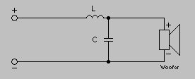
Using the same schematic, 500Hz high pass values are:
L=1.8mH
C=56.25microF
Your bandpass schematic is here:
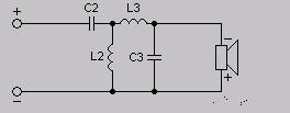
And your values are:
C2=361.80microF
C3=25.38microF
L2=18.41mH
L3=1.50mH ------------- It all reminds me of something that Molière once said to Guy de Maupassant at a café in Vienna: "That's nice. You should write it down."
|