dipole Xover 2: haemphyst, DYohn, et al?
Printed From: the12volt.com
Forum Name: Car Audio
Forum Discription: Car Stereos, Amplifiers, Crossovers, Processors, Speakers, Subwoofers, etc.
URL: https://www.the12volt.com/installbay/forum_posts.asp?tid=42858
Printed Date: May 10, 2026 at 3:06 PM
Topic: dipole Xover 2: haemphyst, DYohn, et al?
Posted By: stevdart
Subject: dipole Xover 2: haemphyst, DYohn, et al?
Date Posted: November 12, 2004 at 9:14 PM
I've got my box of goodies from PartsExpress and am getting familiar with the circuit board and where the components go. (re: my previous post) And I see that C4 and L4 represent the tweeter, and I've followed the others and understand them. I'm not sure, though, how to install the L-pad resistors R1 and R2 onto the board. I think they might follow the same pattern as C4 and L4 and so I show where I think they get wired and soldered in the PartsExpress diagram shown below. 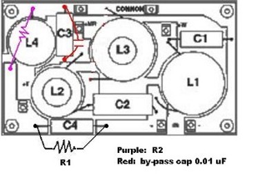
There aren't any extra holes in the circuit board to use. Would they use the same holes as C4 and L4 as shown? The other thing is the by-pass cap I got to use with the 80 uF cap (electrolytic) C3. I read enough in the caps section to think that I should add a .01 uF by-pass to that cap ( it is the highpass at 250 Hz). Would it go in parallel with C3 as shown (uses the same holes)? And the following is the circuit board schematic with R1 and R2 added by me. The by-pass cap isn't added because I don't know exactly where to put it. 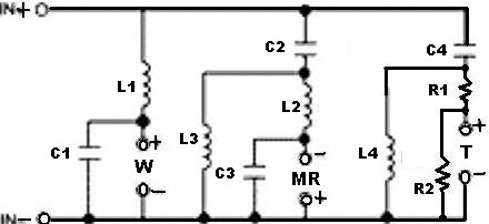
------------- Build the box so that it performs well in the worst case scenario and, in return, it will reward you at all times.
Replies:
Posted By: haemphyst
Date Posted: November 13, 2004 at 12:28 AM
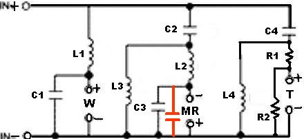
That looks correct, except for the R1 position. I'll draw it up later, and re-post. Been a long day, just letting you know I'm looking at it. Otherwise, the red I added below will show you electrically where the bypass cap goes, and it IS in the correct place on the crossover image.
 ------------- It all reminds me of something that Molière once said to Guy de Maupassant at a café in Vienna: "That's nice. You should write it down."
Posted By: stevdart
Date Posted: November 13, 2004 at 9:11 AM
I showed the wrong cap for the bypass..sorry...it is supposed to be C2: 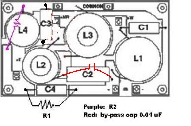
I'll connect the bypass cap at the same board points as the C2 uses. And the R1 and R2: do they just share the same circuit board connections with C4 and L4? The board holes are too small to allow more than one lead to pass through. ------------- Build the box so that it performs well in the worst case scenario and, in return, it will reward you at all times.
Posted By: DYohn
Date Posted: November 13, 2004 at 9:16 AM
You're using a 3-way crossover for your dipoles? Or are you modifying an exiting crossover or stuffing a pre-made board? Hmm. In any case, if you are adding components to a pre-made circuit board, you can solder the leads of one cap, resister, etc. to the leads of another and "stack" them. No need to try and push multiple leads through the pre-drilled holes. I'll look at your circuit after I have some coffee... ------------- Support the12volt.com
Posted By: stevdart
Date Posted: November 13, 2004 at 9:37 AM
Yes, a 3-way as was laid out for me in the first thread (linked above). Stuffing a pre-made board (linked above). Glad to know about the stacking...I was afraid of having to drill through the board. Thanks for taking a look.
-------------
Build the box so that it performs well in the worst case scenario and, in return, it will reward you at all times.
Posted By: DYohn
Date Posted: November 13, 2004 at 9:42 AM
Ah, gotcha. It's not actually a 3-way, it's a 2-way with two different woofer networks. Cool. ------------- Support the12volt.com
Posted By: stevdart
Date Posted: November 13, 2004 at 9:56 AM
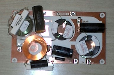
A bit cramped for room on this board. These are just in place, not connected or arranged as neat as possible. The biggest question is the placement of the L-pad resistors. And there's one connection point shared by C2, the bypass cap, and the large coil L2. The coil lead can go through the hole, I take it, and the cap leads can connect to the coil lead as a stacked arrangement. How about resistors on the underside of the board for a better fit, and maybe exchanging the tweeter section with the woofer section so the coils fit better....would exchanging like that cause a problem with the circuit flow? ------------- Build the box so that it performs well in the worst case scenario and, in return, it will reward you at all times.
Posted By: DYohn
Date Posted: November 13, 2004 at 2:10 PM
OK, your circuit looks good. Should work fine and you should hit your 3-4K xover for the tweeters. As far as using the "underside" of the PCB, electrically it is the same. As far as swapping relative positions on the board, it also does not matter so long as your filter network sections remain as described in the original schematic. When you "stack" components, be sure to stabalize them with glue or tie wraps etc. so they do not get moved around and either short out or break off. While some people love them and there is certainly nothing wrong with using them, I personally do not like using these pre-made circuit boards precisely for the reasons you are finding; not enough room, confusing pre-determined layout, holes too small, etc. I prefer to lay my crossover components out on the bench and connect them together using solder and wire (I usualy use teflon insulated 16AWG silver-over-copper hook up wire. You get silver-over-copper by looking for a temperature rating of 200 C on the wire.) Then when the system sounds the way I expect it to, I will insulate the appropriate sections and mount the crossover on a piece of fiber board or plywood using RTV or hot glue to keep things in place. It ends up looking a bit more "like a project" perhaps, but it allows my feeble brain the freedom to visualize the circuit without being constrained by someone else's ideas on a PCB. Just my 2 cents... ------------- Support the12volt.com
Posted By: stevdart
Date Posted: November 13, 2004 at 3:22 PM
Thanks, DYohn, I'll place the L-pad resistors with the same connecting points as the tweeter cap and coil and run them under the board. I'll try switching the W with the T components and see if that fits better. ....and your tip about making a crossover board is the way I'll go the next time.
-------------
Build the box so that it performs well in the worst case scenario and, in return, it will reward you at all times.
|