Total System Tuning
Printed From: the12volt.com
Forum Name: Car Audio
Forum Discription: Car Stereos, Amplifiers, Crossovers, Processors, Speakers, Subwoofers, etc.
URL: https://www.the12volt.com/installbay/forum_posts.asp?tid=52616
Printed Date: March 29, 2026 at 1:09 AM
Topic: Total System Tuning
Posted By: mrmsudawgs
Subject: Total System Tuning
Date Posted: March 26, 2005 at 9:43 AM
Okay. My system is installed, the wife is happy, the neighboors are not, and I have tweaked on the sound settings until I am blue in the face. I think I have the settings optimized but I really don't know. Is there a method to setting up a system to achieve best SQ? Is there a CD to pop in that has test tones? Is there a hand held meter or something I can use to verify cross-over points? What is the best way to tune the whole thing?
Any help will be appreciated.
Mike
Replies:
Posted By: DYohn
Date Posted: March 26, 2005 at 10:10 AM
It depends what you're after, actually. If nothng is clipping or distorting and you like the way it sounds, then "tuning" by ear is perfectly fine and more than sufficient. In fact, there are many audio professionals who always tune by ear and never use meters. So if you're after a great sounding daily driver, you are finished. If on the other hand you're after maximally flat response, or you intend to compete in SQ comps, or you are simply an audiophile who wants to "be certain," yes there are many tools you could use. What you'll need is a real time analyzer (do a Google search and you'll find many of them as well as tips on their use.) These can be very expensive tools, so if you plan to use it once I suggest hooking up with a (high-end) car audio shop and seeing if they have one they will rent to you for a couple hours. ------------- Support the12volt.com
Posted By: mrmsudawgs
Date Posted: March 26, 2005 at 7:34 PM
I am an audiophile wana-be but I'm not there yet so please explain what a "maximally flat response" is. Maximally flat as opposed to what?
Thanks!
Mike
Posted By: DYohn
Date Posted: March 26, 2005 at 8:17 PM
Since there is no such thng as a perfect 100% flat frequency response in any real-world equipment, "maximally" flat refers to using EQ and filters to achieve as close to an ideal flat response curve as possible. ------------- Support the12volt.com
Posted By: stevdart
Date Posted: March 26, 2005 at 8:33 PM
Of your question, there are some CD's available with test frequencies. Here's one I found using a Google search. And here's a portable digital RTA.....very affordable for the average DIYer, don't ya think? ;)
Posted By: mrmsudawgs
Date Posted: March 26, 2005 at 10:01 PM
Thanks for the links!
However, I'm still not clear on the term "flat response curves". Are you refering to the transfer function graphs as shown in the first image on my website as generated by WinISD? If so, are you referring to keeping the curve horizontal (flat) between a lower and upper frequency range?
Mike
Posted By: stevdart
Date Posted: March 27, 2005 at 7:37 AM
The graph chart on that webpage shows decibels on the vertical axis from +6 to -30. Adjust that to +6 to -12 to narrow the printout as you are not interested in output softer than -12 db anyway. The horizontal range is fine for a sub at 10 Hz to 200 Hz. Draw an imaginary line along the 0 db line from 20 Hz all the way to 120 Hz. Imagine that the line falls off at a steep angle below 20 Hz, and curves off at a gentle angle starting at 120 Hz. You would have an ideal flat response if it looked like that. Although there are times that you can create a computer-simulated workup of a response line that DOES look flat, an actual RTA reading after the installation would show you a response that looks different. That's because of the added sound caused by the coupling with the auto environment (cabin gain) and the subtraction of sound caused by cancellation and other things. So, DYohn's advice in his first response is true in every case - "If nothng is clipping or distorting and you like the way it sounds, then "tuning" by ear is perfectly fine and more than sufficient." ------------- Build the box so that it performs well in the worst case scenario and, in return, it will reward you at all times.
Posted By: mrmsudawgs
Date Posted: March 27, 2005 at 8:03 AM
Ah Ha! I get it now. My system does sound wonderful now but what if I had one of those megabucks RTAs that could show me the response curve of my system as installed. If it showed anything but a perfectly flat curve I could upgrade my components, add components, buy accessories, etc. until I got the flat curve I'm looking for. Then, I could improve more by putting DynaMat everywhere to kill the road noise and damping the ambient white noise. I could check it again to see if the curve is flat or not. If not, I could.......NO! NO! NO!.....SOMEBODY PLEASE STOP ME!!!!!  IT IS A NEVER ENDING CYCLE OF SPEND MONEY AND TEST!!
Okay...I need some coffee. I'll leave the RTA alone for now. 
Thanks for the help!
Mike
Posted By: stevdart
Date Posted: March 27, 2005 at 9:09 AM
Ha ha that's funny and so, so true! Here's a true story with me recently: I've been working on a crossover network for a center channel speaker system that I'm building for my HT system. I'm using some new (to me) computer software (Speaker Workshop) that I'm becoming familiar with as I use it. Working on the response curve, and trying to get a flat response from the woofers to the tweeter....and also trying to achieve a proper system impedance.......I ended up designing not just the crossovers but also added a Zobel network and series notch filters for both the woofer network and the tweeter. So for this simple little two-way center channel, I had three crossovers, two series notch filters, an L-pad and a Zobel network. In order to achieve the exact values in the components, I had to use additional components and add them together....for example I used 3 resistors in parallel to achieve a resistance value, and two capacitors in parallel to get what I needed for capacitance. My crossover board ended up with 27 individual components! I ordered everything from Parts Express. Got my heavy package, looked at all those components....then went back to the drawing board and started over. Starting as simple as possible, I found that I could remove BOTH series notch filters and the L-pad altogether and achieve the SAME response that I had with them in the mix. I ended up taking out eight component values consisting of a total of fifteen individual components! Just goes to show that you can work on corrections to the point of being ridiculous, as one correction sometimes necessitates a counter-correction that you're not aware is happening. And simple is better. Now I have a rather substantial component inventory in my workbench for future projects..... Next time I get carried away with tweaking I'll have to think of Michael Jackson's nose....tweaked and tweaked until it fell off. ------------- Build the box so that it performs well in the worst case scenario and, in return, it will reward you at all times.
Posted By: kfr01
Date Posted: March 27, 2005 at 6:58 PM
lol ^^^^^ funny story. Congrats on the more simple xo. :-) How are you liking speaker workshop? Did you build a wallin jig, or just make some cords? mrmsudawgs: I use a relatively cheap RTA setup for the laptop computer. I bought a fairly cheap Behringer 8000 Mic, the IUSB Mobile-Pre from M-Audio, and the TrueRTA software from https://www.trueaudio.com/ If you have a laptop this setup is a great value. ------------- New Project: 2003 Pathfinder
Posted By: mrmsudawgs
Date Posted: March 27, 2005 at 8:31 PM
Good grief Stevdart! I thought I was the only one who could take things to such limits  It is just so easy to dive right in to this stuff and loose track of time, reason, and sometimes sanity!
Thanks for the RTA link kfr01. I think I'm going to ask my installer friend if he has one just to "play" with.
Mike
Posted By: stevdart
Date Posted: March 27, 2005 at 10:51 PM
kfr01] wrote:
ow are you liking speaker workshop? Did you build a wallin jig, or just make some cords?
kfr01, my understanding of how electrical components work together shot way up using that program. It's a real pleasure to know exactly what's behind the tuning of the sounds you here and why the pieces of the puzzle are there. But although my electronics IQ is higher now after using Speaker Workshop for awhile.....I still have no idea what those terms "wallin jig" or "cords" mean....  "I'm Mis-ter Clue-less..." "I'm Mis-ter Clue-less..."
Posted By: kfr01
Date Posted: March 27, 2005 at 11:01 PM
I'm probably not using the right terms. :-)
I was wondering what hardware you're using to test your speakers response and impedence. :-)
-------------
New Project: 2003 Pathfinder
Posted By: stevdart
Date Posted: March 27, 2005 at 11:22 PM
Oh, hardware....well, I have a graph representation of impedance with speaker workshop and when I have this thing built I'll test it with my DMM. For speaker response, I'll use the old standbys I've used all my life..... 
(...just kidding, kfr01, but that's all I have...lol...)
Posted By: kfr01
Date Posted: March 28, 2005 at 12:07 AM
So, you're doing tweaking of the xo response w/o having real driver frequency response information to work with? Please know I'm not criticizing - I am honestly curious about your setup - I haven't been courageous enough to take the dive into crossover designing yet. Sometimes I enter a state I like to call "analysis paralysis" where I research every solution to death and never really act on it. ------------- New Project: 2003 Pathfinder
Posted By: stevdart
Date Posted: March 28, 2005 at 7:45 AM
I'm not tweaking yet...I got ahead of myself. I just have the two-way system set up on paper and diagrams and have the crossover board laid out at this point. I have everything to put it all together but I haven't cut my wood yet. What I was doing was trying to achieve a frequency response (using the software programs) from 120 Hz to 18000 Hz that is relatively flat, and achieve high enough impedance to run this center channel on my system. I'm letting the tweeter response rise higher in db than the lower-than-1000 Hz response because the enclosure will sit high relative to the seating positions and also because I want distinctly clear dialogue. Most likely the only tweaking I will do after assembly is to decide whether to put the L-pad back into the tweeter circuit and whether to make it -1 ohm or -2 ohm. I have the resistors to make either so I'll probably try it out all ways and settle for the best sound I get with that amount of tweaking. And, yeah, I feel confident that my ears will tell me if something's amiss.... ;) Since it's just for my own personal use I won't have to generate a frequency response graph to present along with it like I would if this were a commissioned project...
Posted By: stevdart
Date Posted: March 28, 2005 at 8:35 AM
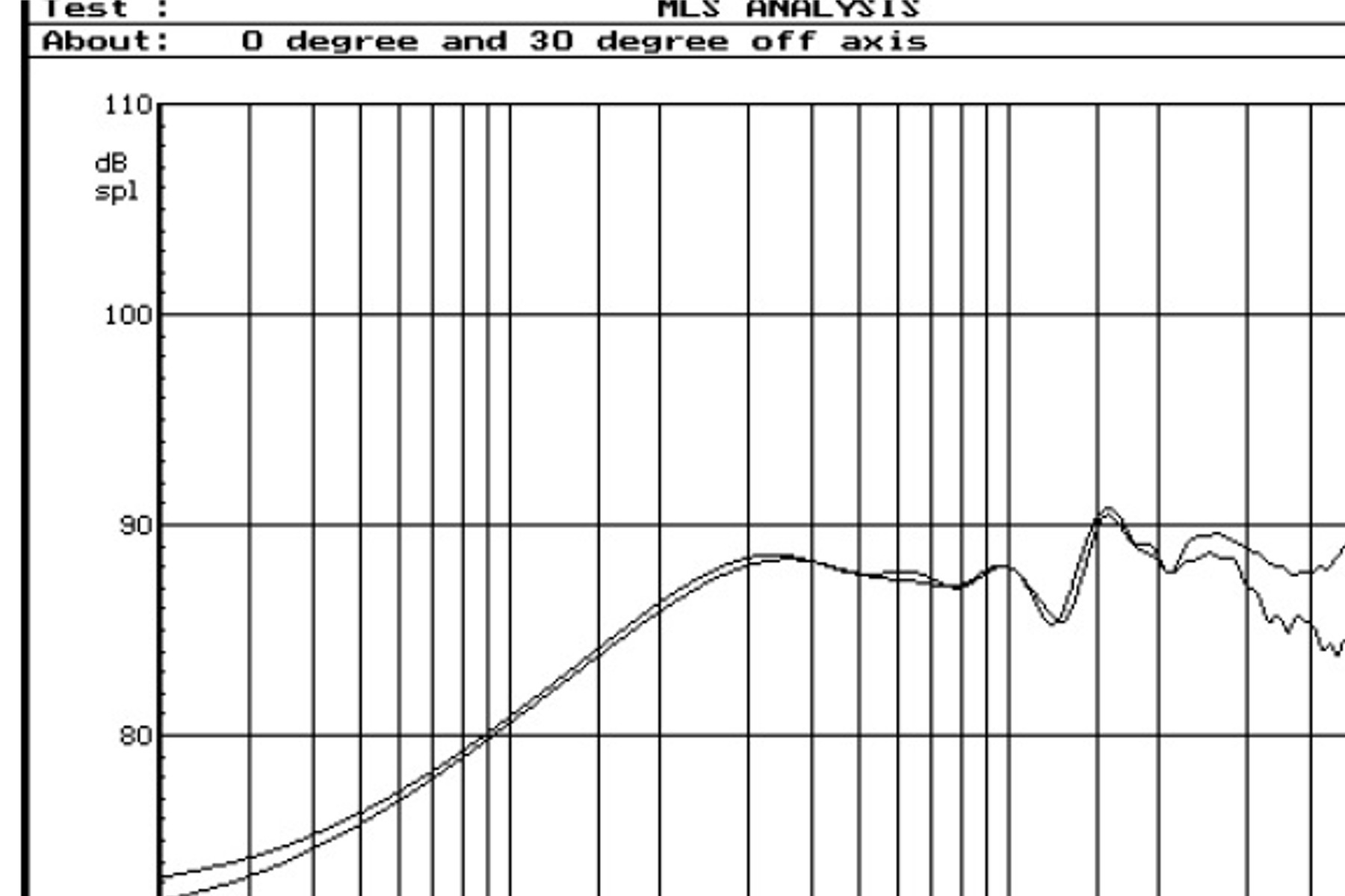
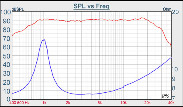
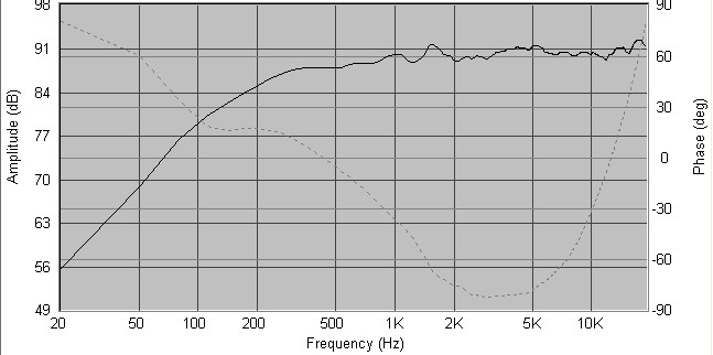
Oh, it just dawned on me where you're stuck trying to envision how I got a frequency response to work with in the first place... I used the program that is a part of the FRD called SPL Trace. I traced the manufacturer's frequency response graphs for the two speakers I'm using and put them together in Speaker Workshop. The crossover and impedance correction circuitry started at that point. This is the original Vifa Infinity woofer response graph: Project1.jpg This is the original Tang Band tweeter graph: 25-669sd_b.jpg I traced those frequency plots along with the impedance plots and they became .FRD and .ZMA files that can be shared among the FRD programs. So they went to both Unibox and to Speaker Workshop to get worked on. This is a response (plotted) using Unibox with two of those woofers and a port, below 1000 Hz: 5C6_VB_Response_Infinity_TC11MG-07-04Xover.gif This is the result of my work in Speaker Workshop with all crossovers and Zobel network added and is what I am stopping at. Copy_of_captured.jpg Now I'm using this response plot along with Unibox's graph (which includes some added low end due to the port) as my intended finished target. What I actually get is what my ears will tell me :).
Posted By: kfr01
Date Posted: March 28, 2005 at 9:53 AM
Ahhhhh Cool. That's exactly what I was wondering. :-)
Neat program!
-------------
New Project: 2003 Pathfinder
|