Aux Input for an Older Delco Radio
Printed From: the12volt.com
Forum Name: Car Audio
Forum Discription: Car Stereos, Amplifiers, Crossovers, Processors, Speakers, Subwoofers, etc.
URL: https://www.the12volt.com/installbay/forum_posts.asp?tid=86365
Printed Date: May 11, 2026 at 6:24 PM
Topic: Aux Input for an Older Delco Radio
Posted By: mickstan_vr
Subject: Aux Input for an Older Delco Radio
Date Posted: November 28, 2006 at 8:53 PM
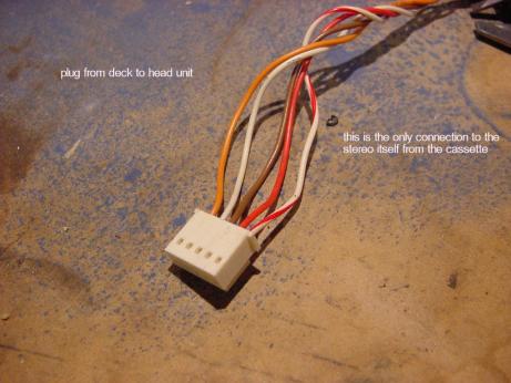
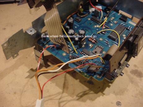
I tried to post this last night, but for some reason it didn't work. Hello. This is my first post here(second now). I've been all over the internet and joined at least half a dozen groups and cannot find out an answer to this. I have a Delco am/fm cassette from a 1988 Chevrolet Celebrity Eurosport VR. The model number is 16041264. Servivice Manual 2H. Its a regular ol' factory stereo from any number of late 80's GM cars. I want to put an AUX 1/8(3.5mm) stereo plug in it to play my iPod through. I have 2 of these stereos torn apart on my workbench right now that I've been tinkering with for quite a long time. I know this can be done as there is now a person on ebay selling the modified radios with the input plug. Here is his description : "It has been bench tested with all repairs being made as needed, including replacement of all burned out illumination bulbs. It then had a 3.5mm aux input jack installed in the faceplate, which is a direct link to the amp, with all new electrical connections soldered inplace for dependability. The unit now has the ability to play virtually any portable music device which features a headphone jack and without having to rely on a fm transmitter cassette adapter, or dummy cassette. All of the radio and tape functions perform just like a stock unit and work perfect as well as the control knobs and buttons. Here is how the aux jack works. When you put the 3.5 mm plug into the jack from your IPOD, MP3, or portable CD player, it cuts the radio signal going to the amp. Which allows the signal from your device to play through the radio's amp and then to your speakers." I'm assuming he's cutting the feed from the radio and replacing it with the feed from the 3.5mm plug at the cassette deck. Thereby fooling the amp into thinking its being fed by the cassette signal. I figured out how to cut the radio signal, but can't get a signal from the mp3 player. There are 5 wires connecting the tape deck to the rest of the stereo RD, R/W,BRN,OR,and W. I put a switch in the red wire. That cuts the radio signal going back to the amp in the RED / white wire. I spliced into the other 3 wires with a 3.5 stereo receptecle. When the switch is thrown, it cuts the radio signal, and should allow the mp3 signal to pass to the amp. Should being the key word. So I put the switch in the R/W wire. Now I get a signal, but its overpowering the amp. The speakers only "thump" the bass line of a song. So I then put some 100uF caps on what I think are the 2 channels from the iPod that I spliced into. The music is now there, but is weak, and I'm getting noise from the tape head I believe. Heres some pictures if that will help. 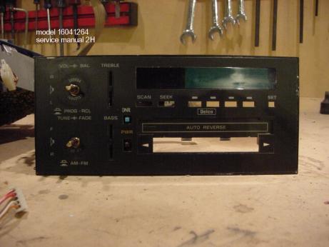
This has GOT to be a simple mod, but I have absolutely no experience at this stuff, nor proper equipment. Ideas? Anyone????
Replies:
Posted By: master5
Date Posted: November 29, 2006 at 3:17 AM
I have never attempted this before..probably because the mp3 technology is relativly new..so no real demand. Basically I am in the business to install and SELL. So if a unit comes in that is not compatable..it is an easy sale to upgrade to a unit with mp3 inputs instead of modifying a 20 year old delco tape deck. However, on a newer model with a nicer head unit..it might be something worth attempting..we all know how lousy FM mods sound. But, I respect anyone willing to perform custom unique stuff and will tell you how I would attept this. ok..we know a tape head adaptor works. So all we need to do is connect to the tape head left and right audio signal wires behind the tape head..and somehow get the head unit to switch to tape mode. Try to find the wire(s) on the switch that switches the deck to tape mode and check with a meter what signal is on the wire(s)...don't forget to ground the shields or expect hum. If you can't get it to switch to tape mode by using the plug itself..install a switch or relay..or perhaps you can modify an exsisting switch or button on the delco to perform this function. Seems simple to me. I had a delco lying around but I just installed it into one of my old cars I am selling. Next delco I come across (I do often but usually toss them out..have no real use) I might attempt this myself for giggles. If I can get it to work before you do I will post back what I find. Best of Luck and keep at it. -------------
Posted By: i am an idiot
Date Posted: November 29, 2006 at 8:25 AM
You are on the right track with your approach the only problem I see with Master's plan is that the cassete head has an output in the microvolt range and you MP3 has probably about 1 volt output. We will have to find a place to tap in after the Head amplifier, I will look around at work to see if I have a deck of this type and will post tonight.
Posted By: master5
Date Posted: November 29, 2006 at 7:56 PM
If tapping off the tape head was a problem why do the casette adaptors? Regardless, if there was an issue with too much input voltage we could take the guts out of an adjustable LOC (or maybe just a simple resistor)and put it somewhere inside the head unit..theres really to much to them. Theres no real guarantee that doing after the head amp will not have problems either..and then finding a way to switch the source as well..but I do agree that is another approach..I was looking for the simplest way that has no reason not to work. -------------
Posted By: mickstan_vr
Date Posted: November 29, 2006 at 9:34 PM
Hey thanks for the quick replies! Had no time to mess with it tonite, and a friend is loaning me digital multimeter tomorrow. You'd laugh at my rinky-dink multimeter I've been using for this. I agree that it should probably go thru the tape deck somehow. I'll post some more pictures tomorrow and a little more of what I've learned in this adventure. Thanks again!
Posted By: haemphyst
Date Posted: November 30, 2006 at 9:11 AM
OK... Right track, indeed. These will be "shot-in-the-dark" suggestions, but here we go!
1: At least one of those wires must be power. If the chassis serves as the ground, then only one, otherwise two will be power - a +12v and a ground. Have you discovered these? Those, you will leave alone. We are only interested in the signal wires.
2: There is probably a pre-amp on that transport circuit board, and the output signal is likely in the .5V range (it'd have to be MUCH higher than microvolt levels, as there is no shielding on the output wires), which you won't be able to find with a VOM, you'll have to have an o-scope, to examine signal levels that low.
3: Locate the functions of all 5 wires, with color codes, and re-post them, and I'll see what I can do further for you. I have a buddy who is an absolute WHIZ with repairs, and I bet he could tell me how to achieve the desired result.
-------------
It all reminds me of something that Molière once said to Guy de Maupassant at a café in Vienna: "That's nice. You should write it down."
Posted By: mickstan_vr
Date Posted: November 30, 2006 at 7:37 PM
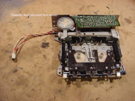
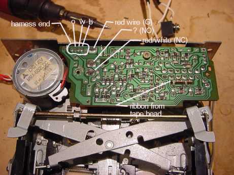
OK, Heres some pics. These are showing the cassette deck and underside of the board on it. The red (R) wire sends a signal or power to the deck and the radio. The red and white(R/W) wire returns a signal to the amp. On the microswitch, the R is on the (G) terminal. R/W is on the (NC) terminal. The R/W wire is connected to nothing else on the board or harness. When the switch is thrown, the R/W is disconnected, the radio quits, and power is sent to the deck thru the (NO) terminal. I spliced into the 3 remaining wires. I think that the brown(B) wire is a ground, and the orange(O) and white(W) are the left and right channel positives. Haven't figured out which is which. If I trip the switch manually,no tape inserted, it cuts the signal and allows music from the CD player to pass thru. But ONLY if I have the 100uF caps on the channels from the spliced in wires. Are you still following me?........ No caps and the signal is too much, and it wont play, it just thumps bad. And I get the hum. And some of the radio sound. With these caps the signal seems to be a tad too weak. I'll mess with it some more and post back soon! and no digital multimeter tonite, the weather here turned bad(St.Louis) so my buddy didn't come over with it........ 
Posted By: mickstan_vr
Date Posted: November 30, 2006 at 7:38 PM
WOW!!!! lets try that again.............. 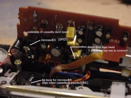
Posted By: master5
Date Posted: November 30, 2006 at 10:55 PM
when I stated "checking signal" I was refering to + and/or - voltage for switching in and out of tape mode..not audio. If you do not have access to an o-scope for signal you can do it "trial and error" method by hooking the unit to a test bench and sending an audio signal to random wires from the tape head that have previosly been verified as not having voltage or ground. The leftover wires must be audio as there is not that much to a tape head. You will hear audio when you are on the right wires. -------------
Posted By: master5
Date Posted: November 30, 2006 at 11:03 PM
Also..in the picture you show an spdt switch..and a n/c switch. We can assume the n/c switch is opened when a cassstte is inserted..a no brainer..but what is happeneing with the spdt..once i know this I can guide you to the switching method you can use to perform this function without needing to insert a tape.
-------------
Posted By: mickstan_vr
Date Posted: December 01, 2006 at 11:10 AM
I do not have access to a o scope so thats out. And I'm getting sound from the O,B, and W wires. The spdt switch and the n/c switch are one in the same. You're just looking at the 2 sides of the board. My terminology might not be too good. The R and the R/W wires from the harness end up at that switch. R on the (G) terminal and R/W on the (NC) terminal. Yes, the switch is opened when a tape is inserted, killing the radio. The R/W wire goes to nothing else on the board. It goes back to the radio. So I'm assuming the remaining 3 wires are carrying the cassette signal. And I think B(brown) is the common or ground. When I trip the switch with a jumper wire across the G and NO position the cassette mechinism fires up, the motor starts, and it acts like there is a tape in there but there is not. I can then get sound from the CD thru the spliced in wires. But I'm also still getting radio sound at the same time (along with the hum from the tape head) because the switch has not been moved physically from the NC position. Somehow that switch has to be thrown without actually putting in a tape. And I need to know exactly which wire would be the ground for the CD headphone out. Can't figure out how the guy on ebay is doing this. He's done it to many different Delco radios from the early '80s to about '97. There has to something in common with all of them. A stereo headphone plug, a couple of wires, some solder here and there. We had quite an ice storm here last nite and the power is still out. Might not get it back for several days! And is gonna get down to 15 degrees for the next 3 nites. So any experimenting at my end is on hold.
Posted By: master5
Date Posted: December 01, 2006 at 1:51 PM
Ice storms? I remember those. Now I live in hurricane ally. No ice but plenty of rain and wind. and long power outages so i feel your pain. This is a tricky one since i do not have a delco tape deck to experiment on at the moment..but as I stated if a casette adaptor works (you might want to actually try one) and the levels are good with no "hum"..you should be able to do it through the head wires in all logic. as far as the switching I know it uses a mechanical switch..this would be much simpler if it was a full logic deck.but not so. However, to do it this way (I have no idea how the other guy does it.he might be a delco engineer for all we know...or very lucky..lol) we would need to "mimick" everything the wires from that tape switch do or expect problems. Keep us posted once everything thaws....best of luck. -------------
Posted By: geepherder
Date Posted: December 01, 2006 at 7:17 PM
It actually sounds pretty straight forward. You don't have to understand all the inner workings of the cassette deck. You just need to be able to replicate what the cassette deck's harness does using your 5 wires.
You've already identified the red and RED / white as coming from the microswitch. You've also identified the orange, brown, and white as audio. That means the hard part is over.
When you get a chance, use an ohmmeter to test across the red and RED / white wires when you manually activate the microswitch. If you get a reading of almost zero ohms, you can put a simple switch across these two wires. If you get a much higher reading, just put a resistor of that value inline with the switch. Extend the wires however you see fit to place the switch where you want it. Now the remaining wires will be your new aux in. I would probably use some 100k ohm pots on the leads and do some trial-and-error. The pots will allow you to avoid damaging the deck. Start out at the high end of the scale, and work your way down.
Good luck, and let us know how it turns out.
-------------
My ex once told me I have a perfect face for radio.
Posted By: mickstan_vr
Date Posted: December 04, 2006 at 5:41 PM
Well, I'm still without power at home! No work on the project. I'm not too savy with this stuff...so what the heck is a 100k ohm pot? And a switch. Is there a 3.5mm receptacle with a switch built in? I got one at Radio Shack, but it doesn't work like I thought it would.I has 5 pins but I need one that will break a circuit when the plug is inserted,....i think... Dang it! I wish I had power! I'd go and check out what geepherder says and take another look at that switch.......
Posted By: geepherder
Date Posted: December 04, 2006 at 7:22 PM
Sorry, pot is short for potentiometer, or variable resistor. I say 100k ohm, or 100,000 ohms because it's a high enough value, it should be safe to use even if you hook up the wires wrong.
For the switch, I'd just use a simple toggle switch. It won't have to be big, and you can mount it wherever you like. It'll just replace the switch inside the cassette deck, and whenever you want to go to your aux source, you'll just manually flip it.
Now just wire up a stereo jack for your input and you should be set. I recommend doing this with a friend who's handy with this kind of project.
-------------
My ex once told me I have a perfect face for radio.
Posted By: mickstan_vr
Date Posted: December 04, 2006 at 9:23 PM
Well I wish I knew someone with those skills and electrical knowledge. I have asked just about anyone I can think of, and this is where I'm at! But I'm not afraid to learn. So just bear with me on this...I really want to figure this out. I'll look at the 'Shack for some "pots". Should I get 3? or 2? And as long as I'm there....Anything else, as far as parts, that I should pick up?
Posted By: geepherder
Date Posted: December 05, 2006 at 7:03 PM
You should be able to handle it. It may just take you a little longer than it would otherwise.
I'd use one for each of the audio wires (3), at least until you get them figured out for sure. They should have a pack of miscellaneous pots, which may be cheaper than getting them individually. Either way should work fine. Like I mentioned before, these values are not set in stone, I just picked 100k because that's an easy value to find, and should not cause any damage if you hook it up the wires wrong.
RadioShack also has some project boxes of different sizes if you want to use one. You can mount a circuit board inside to protect it, and mount everything there.
-------------
My ex once told me I have a perfect face for radio.
Posted By: mickstan_vr
Date Posted: December 05, 2006 at 8:13 PM
Ahhhh....thats a cool idea! I'll see about that. Got the power restored about 3PM today, and picked up the multimeter. Its a FLUKE 87 True RMS Multimeter. It looks most impressive! My buddy showed me how to do a few things with it, so we'll see if I can get it to work.
Posted By: mickstan_vr
Date Posted: December 06, 2006 at 9:02 PM
Well my radio gave up the ghost tonite while fiddeling with it. Puff of smoke from the amp area. I did get a breadboard and got it hooked up.I just cut up a cassette harness and put the board in the middle, and then ran a ground between the radio chassis and the deck. Sweet idea, geepherder!!! Tomorrow I'll swap in another amp that I have here. Don't know if its any good either! If not, then its off to another junkyard! I got a stereo volume control potentiometer while I was at the 'shack today, 100k, and some 47uF capacitors. But I never made it far enough to put them in and experiment. I'm at a standstill....... again :(
Posted By: geepherder
Date Posted: December 08, 2006 at 5:17 AM
You're factory radio started smoking? Were you hooking this up without the pots in place? You didn't leave the other end of these wires connected to the cassette deck, did you? When you do this you'll want to cut off the 5 wire harness to hook everything up and test before final install.
-------------
My ex once told me I have a perfect face for radio.
Posted By: mickstan_vr
Date Posted: December 08, 2006 at 3:47 PM
Well.....I was getting a bit of help from my 15 year old son....and I'm not really sure what happened. No big deal. It'll just set me back a little. Yes everything was hooked up to the breadboard and being tested in its stock configuration. Then poof! I'll post some pictures of the set-up later.
Posted By: geepherder
Date Posted: December 08, 2006 at 7:18 PM
Ouch! You probably either shorted some wires together, or overloaded a circuit. Was this testing done with the pots in place?
-------------
My ex once told me I have a perfect face for radio.
Posted By: mickstan_vr
Date Posted: December 08, 2006 at 9:32 PM
No the pots were not in yet. We just wanted to verify that all of our connections worked and the radio functioned as it should with no modifications. Everything was working fine. I'm not sure, but something touched a wire it shouldnt have. woopsie. I got all of this stuff and now the radio crapped out. figures.
Posted By: mickstan_vr
Date Posted: December 11, 2006 at 7:55 PM
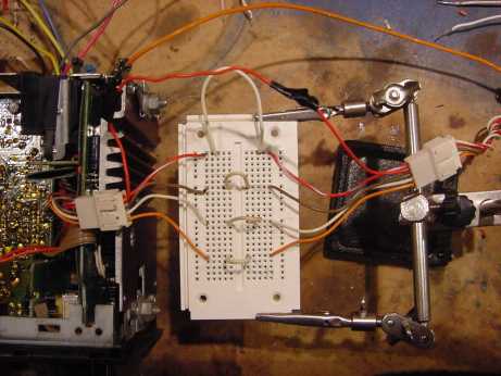
Heres a couple of pictures of the test set-up....... 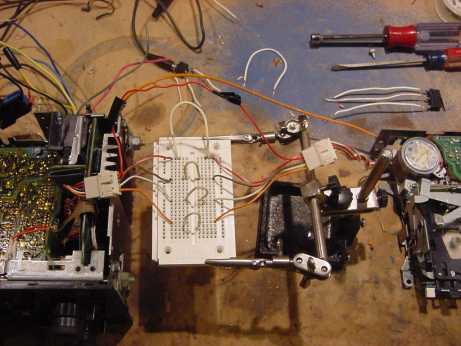
Posted By: geepherder
Date Posted: December 11, 2006 at 9:18 PM
From the pictures it looks like you simply connected color to color using the project board. What is the reasoning behind this? The idea is to test the 5 wires while the cassette deck is playing, then simulate this process to create an aux in while removing the cassette deck from the equation altogether.
It also appears you've dissassembled the deck. There's no need to do this. Once you've identified and verified the functions of the wires, you'll just plug in the pigtail you cut off the cassette harness, and wire it in.
-------------
My ex once told me I have a perfect face for radio.
Posted By: mickstan_vr
Date Posted: December 12, 2006 at 5:43 AM
Well I had to take the thing apart to get to the wires! Its easier to test with it opened-up. And the deck itself is still intact and functioning, it has just been removed to gain access to the internal harness. And yes it is set up color to color. Heck, I had to start somewhere! The board serves as a place to "intercept" the signal from the deck. It functioned just fine, for a minute. We never made it to the next step.....Verifying functions.
Posted By: geepherder
Date Posted: December 12, 2006 at 6:58 PM
Now I understand- you were still testing. You wouldn't have needed to open the factory deck, though.
-------------
My ex once told me I have a perfect face for radio.
Posted By: mickstan_vr
Date Posted: December 19, 2006 at 5:40 AM
Opening the deck is the only way to get to the wires. If I didnt open it up, how else could I get to them? The wires are inbetween the deck and radio. Its all one unit. Not 2 seperate components. I wish I didn't have to open the thing up!
Posted By: geepherder
Date Posted: December 19, 2006 at 6:16 AM
Okay, I thought they were two seperate components.
-------------
My ex once told me I have a perfect face for radio.
Posted By: mickstan_vr
Date Posted: January 23, 2007 at 5:37 PM
Well I got tired of waiting for a nice day to go junkyarding a look for a working delco radio. Soooooo...I caved in and bought one with the aux input from the dude on ebay. As soon as I get it, I'll open'er up and see what makes it tick.
Posted By: jayv8
Date Posted: February 12, 2007 at 6:17 PM
did you ever take your ebay radio apart and figure it out ? this seems like an awesome mod that would be perfect for my v8 fiero -if not i'll take mine apart and see if i can figure it out
Posted By: jayv8
Date Posted: February 13, 2007 at 10:15 PM
ok, i figured this out -not much on these radios on the net -this is very simple hack, i searched the internet longer to not find any info then to just figure it out myself -i attached a pic of the connector to understand what i am talking about -the radio i used is from an 86' pontiac fiero -firebirds/camaros also had similar units (among others) -1. take the bottom cover off the radio 2. find the connector next to the cassette part and pull it out, no need to disconnect there is plenty of wire -the orange wire is the right audio input, the white is the left audio input, the ground just gets connected to the radio itself 3.this is the tricky part, now you need the cassette deck to think there is a tape in there -if you dont care if the cassette deck ever works again, cut the orange and white wires and just solder to the radio end and just stick a tape in the deck everytime you want to use your aux input -there is also several other methods, one method is to solder a switch between the brown and red wires and flip a switch everytime that also allows you to still use your cassette deck -the best method is to wire this up to a jack and get one of those jacks that has a switch in it so everytime you plug into it, it triggers it -a couple of side notes on this though, these radios arenet that great for overall sound quality -i was going to do this so i could put my stock radio back in for the look but after hearing the radio i put my pioneer one back in -still a neat no budget hack though -hope this helps someone into the right direction 
Posted By: master5
Date Posted: February 14, 2007 at 10:32 AM
Yeah this sounds like what I reccomended to do way back in the beginning of this. I saw no reason why that simple "hack" method into the tape head audio wires and using a switch to "trick" the unit to thinking a tape was in it shouldn't work. However I did always wonder why anyone would really want to do this to a delco as there are many aftermarket decks out there with aux inputs as well as ipod interfaces very fairly priced that would sound alot better then an old delco. But regardless if for some reason someone was really attached to an old delco we see it can work if sound quality is not a concern. -------------
Posted By: mickstan_vr
Date Posted: March 22, 2007 at 5:49 PM
Hey guys, I did get the radio from the guy on ebay. Got it all figured out now. The tape deck is NOT the way into the amp for this mod. I have improved on his method and I am now selling the complete radios and input "kits" (with detailed instructions) on ebay myself. Its a very simple mod. No switches. No tape adapters. The radio and tape deck work normally. This will work on 90% of GM Delco radios from 1982 thru 1999. Do a search for "delco ipod" on ebay and you'll find them. As for why I would do this? I want to retain the stock look of the interior of the car. The aftermarket radios never fit in the space without adapters, and I personally think they look like crap. The headunit itself sounds just fine, and with an iPod hooked up directly to the amp, its CD quality!
|