tuning a box to the wave length of a car?
Printed From: the12volt.comForum Name: Car Audio
Forum Discription: Car Stereos, Amplifiers, Crossovers, Processors, Speakers, Subwoofers, etc.
URL: https://www.the12volt.com/installbay/forum_posts.asp?tid=94398
Printed Date: March 25, 2026 at 8:59 AM
Topic: tuning a box to the wave length of a car?
Posted By: StealthEs
Subject: tuning a box to the wave length of a car?
Date Posted: May 31, 2007 at 1:10 AM
Hey guys, on a forum a visit I came across this
"its tuned to the standing wave length of the car ...so in other words its tuned to the subs and the car"
After asking for an explanation I got this.
"to keep it simple...you measure from the front window to the rear window and then divide that by 1130 which is the speed of sound? correct me if i'm wrong...then that will give you about 125 hz...then you half the frequency to 31.25 and then based on that you figure out your port"
Have any of you guys heard of this before?
-------------
Cris
Replies:
Posted By: mikegar
Date Posted: May 31, 2007 at 1:47 AM
Posted By: jmelton86
Date Posted: May 31, 2007 at 4:18 AM
Anyone have a better way of explaining this? Does the vehicles' fs have anything to do with this?
I'd like to find mine.
-------------
2013 Kia Rio -90a alternator
DDX470HD GTO14001 GTO1014D (x3)
Big3 in 1/0G
1/0G to GTO14001
Posted By: wormy
Date Posted: May 31, 2007 at 7:08 AM
-------------
...typically, I just run whatever I randomly pick up off the floor.
1995 Ford Ranger Supercab
MECA member
Team CSS
Posted By: sarcomax
Date Posted: May 31, 2007 at 11:19 AM
Posted By: wormy
Date Posted: May 31, 2007 at 1:22 PM
-------------
...typically, I just run whatever I randomly pick up off the floor.
1995 Ford Ranger Supercab
MECA member
Team CSS
Posted By: wormy
Date Posted: May 31, 2007 at 1:26 PM
-------------
...typically, I just run whatever I randomly pick up off the floor.
1995 Ford Ranger Supercab
MECA member
Team CSS
Posted By: jmelton86
Date Posted: May 31, 2007 at 7:21 PM
Vehicles' panels, as any part of the vehicle really, has its own fs. This is due to the size, the way it's held in place, where its held in place, along with innumerable(sp?) other factors that affect the particular piece. Now, the vehicle is actually louder at one frequency than others -just where the panels hit 'common ground' with each other. This is the actual fs of the vehicle.
What I want to know is would building a ported box tuned to the vehicle fs be the best way of getting a comp-worthy vehicle?
Also, since to have the front and rear waves hit the mic at the same time is optimum for comps, how would one going about this? -what this thread was started for, I think.
-------------
2013 Kia Rio -90a alternator
DDX470HD GTO14001 GTO1014D (x3)
Big3 in 1/0G
1/0G to GTO14001
Posted By: wotugot4me
Date Posted: June 01, 2007 at 7:55 AM
StealthEs wrote:
"to keep it simple...you measure from the front window to the rear window and then divide that by 1130 which is the speed of sound? correct me if i'm wrong...then that will give you about 125 hz...then you half the frequency to 31.25 and then based on that you figure out your port"
hee hee, just noticed half of 125hz is not 31.25, thats a quarter. I missed that the first time I read it.
Posted By: zhalverson
Date Posted: June 01, 2007 at 6:32 PM
StealthEs wrote:
Hey guys, on a forum a visit I came across this
"its tuned to the standing wave length of the car ...so in other words its tuned to the subs and the car"
After asking for an explanation I got this.
"to keep it simple...you measure from the front window to the rear window and then divide that by 1130 which is the speed of sound? correct me if i'm wrong...then that will give you about 125 hz...then you half the frequency to 31.25 and then based on that you figure out your port"
Have any of you guys heard of this before?
This sounds like finding the theoretical second order harmonics of the vehicle. Cutting this frequency in half would give the 1st order or fundamental frequency of the vehicle. Cutting it in half again like done above is, well, nothing. I'm no expert but I think this is pretty useless. I may be wrong but it seems like physics applied incorrectly which seems to happen alot with little methods like this. Sometimes you just can't simplify things.
Like jmelton said there are many factors that make up the resonant frequency of a vehicle. I got curious about this so i did some researching and ran across a thread: https://forum.ecoustics.com/bbs/messages/4/345879.html
Posted By: wormy
Date Posted: June 03, 2007 at 11:34 PM
I'm not saying its a simple process, but this is the part that I'm most interested in. I can do tests all day long, but that gives me less of a direction than understanding the concept of the waves. If I could understand how to predict at least the general reflections of the waves, then I would at least have some direction.
-------------
...typically, I just run whatever I randomly pick up off the floor.
1995 Ford Ranger Supercab
MECA member
Team CSS
Posted By: wormy
Date Posted: June 11, 2007 at 9:26 AM

This should be one part of the whole formula in finding your resonant frequency. There is an easier and more straight forward real world method that doesn't require a bunch of formula's. The formula's are just so cool though! lol. The formula you were using was n * v / 2 * L. The "n" stands for the resonant frequency frequency that you which to obtain. If you plug one into the "n" variable, then you will obtian the fundamental frequency, two while obtain the 1st overtone, three will obtain the second overtone, and so on. "v" is the speed of sound. Different temperatures will equate different velocities for the speed of sound. "L" is the length you are trying to determine a resonant frequency for. That equation takes the order of the frequency that you are trying to find, in your case the 1st fundamental frequency, which is 62.5 Hz, and determines the frequency. Not very useful alone, but if you were to find enough of these throughout your vehicle and matched the wave coming out of your enclosure to that resonant frequency and controlled that wave so that it would follow that path until it reached the point in which it was to be measured, then, theoretically, it should boost your SPL.
The more realistic method is to forget about the physics of it all and just use a meter and sine waves to test the actual SPL at different points. To do this, play several different, individual sine waves. Set the meter whereever you need the system to be the loudest. Find the loudest frequency in that location. Next, play the sine wave that you determined to be the loudest and move your enclosure into different positions to determine the loudest one for the location you are testing. Finally, retest for your loudest frequency and change it if another one took its place. You can use programs, such as WinISD, to build an enclosure that will maximize your vehicle's resonant frequency.
I've known about that method for a while now, but I decided to give your method a try. I knew that the one resonant frequency alone wouldn't do you any good, but I wondered if I might accurately determine my own using the formulas when I worked enough of the resonant points up. Maybe when I understand the nature of waves better...lol. My resonant frequency, for the fundamental, came out to be 101 Hz. I know my resonant frequency to be 70 Hz. So, that one resonant frequency alone isn't enough. You need to calculate alot of different paths.
-------------
...typically, I just run whatever I randomly pick up off the floor.
1995 Ford Ranger Supercab
MECA member
Team CSS
Posted By: speakermakers
Date Posted: June 12, 2007 at 4:28 AM
1. Space loading. Space loading is when sound reflects off a solid surface and amplifies its self in the process. This effect increases as frequency drops and is the prominent reason for the large boost in bass in cars. The predicted in car response that most box programs generate for you use this and only this to predict transfer function. This alone will not give you an accurate prediction with in 12db.You can find out more about this here https://www.trueaudio.com/st_spcs1.htm
2. The second is due to standing waves. There are multiple standing waves in the interior of a vehicle do to the many parallel solid and semi solid reflective surfaces. Check out this video of an experiment that shows how standing waves are frequency dependant and become more complex as frequency rises. https://www.youtube.com/jp.swf?video_id=Zkox6niJ1Wc&eurl=http%3A//en.wikipedia.org/wiki/Standing_wave&iurl=http%3A//img.youtube.com/vi/Zkox6niJ1Wc/2.jpg&t=OEgsToPDskKC1Ua75Pj7BZMCFHMC35jD&autoplay=1. Notice how the effect is always more drastic near the perimeter of the acoustical area. This is why standing waves in a vehicle are so important. Due to the close proximity of your head to a wall at all times in a car the effect is dramatic.
3. The next is diaphragmatic absorbers. There are many surfaces within a car that will act as an acoustic reflector at certain frequencies and as an absorber at others. This is aggravated by the presence of standing waves at frequencies that over lap these points. One way to battle this is to reduce the gain at the problem frequency in only one channel in a stereo situation. This can actually cause an acoustic gain from the listening position due to the standing wave null physically shifting away from the listening position. This is why Audiocontrol EQs have discrete L and R adjustments.
4. The next is multiple resonant chambers interacting with each other causing new standing wave formations as well that I like to call third party resonances. This is where for example the trunk resonates at one frequency but also resonates at a second frequency when combined with the resonant frequency of the passenger compartment. I know of no accurate way of predicting this in the car environment. In loudspeaker design I deal with this all the time. For example a speaker has a resonant frequency and the enclosure has a resonant frequency and when combined this produces a new resonant frequency. Due to the well documented attributes of enclosure building materials and construction this is not nearly as difficult to predict with in an enclosure. Vented enclosures are a prime example of how this effect can be advantageous. Though this can not be accurately predicted before hand, knowing about it and being able to identify the phenomenon while performing a transfer function test will enable you to take advantage of the phenomenon rather than fall victim to phenomenon.
I have barely scratched the surface of this topic here. There is simply not enough room, but I hope that I have led you to the information that you seek.
There is however a rather simple and scientific solution to a cars low frequency acoustic environment. If you own a computer and a cheap computer microphone you can test your cars transfer function for free and then attempt to either reverse engineer the situation to better understand it or you can take that info at face value and design a sub box taking that information into account. Once you have your vehicles transfer function in hand you can import that info into a program like bass box pro or leap enclosure shop and then see how various box designs with various tuning frequencies will interact with your vehicle.
So whats the answer to how do you find the right frequency to tune your box to after understanding your vehicles transfer function? This involves becoming familiar with what frequency response curves, cone displacement curves, and group delay curves will get you what you are looking for. I will try to comment on this in future posts but dont have the time now. But its really not that complex compared to the rest of this.
To test your vehicles transfer function download OscilloMeter 4.14(free) or pay for TrueRTA $39.95 (better- way more user friendly). Using this software and a regular mic you can send a pink noise (the free version of TrueRTA comes with a good pink noise generator that you can pipe into your system) signal to your amps and use your cheap mic to sample the out put of your sub(s).
First run a long wire from your sub amp to your sub and place your sub on the ground out side of your car. Then place your microphone 2 meters from your sub and place it on the ground pointing towards your sub.
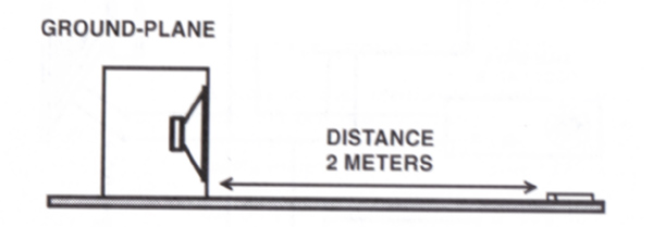
Find a relatively empty and noise free parking lot (no traffic or people) with no buildings or large surfaces within 30 ft. I show up to work early before anyone ells and place the sub box near the corner of my shop (I cant get 30 ft. from a building). Placing the box at the corner drastically reduces any reflections that the building can send back to my mic. At 30hz any surface within 37.69 ft. of the sub will color your results by at least 6db and that gets even worst as frequency goes down so dont under estimate the reflections. In this test the ground acts like a reflector and will boost your results by 6 db. Thats the reason why we place the mic 2 meters away. Sound pressure drops 6 db at every doubling of distance so this is the equivalent of placing the sub 1 meter from the mic in the car. When we test in the car we want the mic positioned where we sit. If this is more les than 1 meter we adjust the results by X db using the formula that sound decreases by 6 db for every doubling of distance and our reference distance is 1 meter. The short cut way of doing this is to ignore it. A sub in a car is usually more than 2 meters from the listener and we are more concerned with larger effects on frequency response to the tune of 12 db. This sensitivity information is only for reference and may be quite useful to you in the future. I reiterate dont under estimate the effects of reflections in your test.
Now you have to record the amplitude of every frequency at every 1/3 octave. Keep in mind that cheap mics have low SPL limits. If you exceed the limitations of your mic all test results will be useless. The reason why we dont need expensive calibrated equipment for this test is that its all relative. You are simply testing the difference in sensitivity (every1/3 octave) at the output of your sub first outside of the car and then inside of the car. And then importing that information into a program like bass box or leap. I dont know if win ISD is capable of that. If anyone knows for sure I would like to know. You dont need to worry about calibrating your sound card or your mic for this test. You dont have to worry about if your mic is weighted for this test. Once you have completed this test outside of the car and then from the listening position of the car you can subtract the outside test from the in car test and you will have the transfer function. If you are going to even entertain the idea of this test You will probably need more info than I have stated here. Feel free to ask. I never learned trig and never graduated high school so I envy your education. I would be honored to assist in any way.
You are not likely to find all of the information required to accurately describe the acoustical environment in a vehicle in a single location. The reason for that is some what complex but in short the educated and experienced engineers that could potentially understand the answers to this either have little interest and experience in the subject as it pertains to cars or simply have bigger fish to fry.
Posted By: speakermakers
Date Posted: June 12, 2007 at 4:57 AM
Posted By: wormy
Date Posted: June 12, 2007 at 2:21 PM
...lol. I don't suppose its too hard to believe that you never completed high school and yet still managed to become so intelligent. School only slows some people down!-------------
...typically, I just run whatever I randomly pick up off the floor.
1995 Ford Ranger Supercab
MECA member
Team CSS
Posted By: jazzcustom131
Date Posted: June 12, 2007 at 8:16 PM
thank you for ending his nights of sleep.... and mine too.
Haemphyst, Dyohn, Alpine... and all the rest of you guys that know more than I could ever put into a book (though i'm tempted, but it would be a pain to write you guys out royalties, so screw it)
lets pour out some info, yeah? It's alot easier for me and wormy to come to you guys than spend hours scouring the internet for false leads...
course that doesn't mean I won't be occupying the engineering halls of the 5 major colleges here in Colorado Springs...
wormy, i'm gonna beat you senseless for making me use my brain when I get back to the south...
-------------
Greed is for amateurs.
Disorder,chaos,anarchy now THAT is fun!!
Posted By: wormy
Date Posted: June 12, 2007 at 8:59 PM
No sleep tonight, that's for sure...lol. Do be expecting several phone calls tonight jazzcustom131!! Its going to be a long night. Thank you so much for introducing me to the12volt. It sure beats spending endless nights at the University Library down here...lol.
-------------
...typically, I just run whatever I randomly pick up off the floor.
1995 Ford Ranger Supercab
MECA member
Team CSS
Posted By: speakermakers
Date Posted: June 13, 2007 at 12:18 AM
I have to say though that all of the information that I have is based on my own tests that are limited to my education and the material that I have read. I am very interested to find out what one of your professors think about some of this stuff.
I believe that there is no practical way or need to direct the waves due to the fact that the gain is prominent and predictable in the areas where both your head and the mic will reside. Having said that I do have several methods that allow you to kill unwanted standing waves. Though most of these methods are only required and useful when you are attempting to pass sound through a space without coloring it before it reaches another destination. I use these type of techniques largely in marine applications.
Thanks for the props guys thats what makes me write this stuff. Its nice to know that I am not the only one who ponders this stuff.
Posted By: wormy
Date Posted: June 13, 2007 at 9:00 AM
I was trying to direct the wave and measure its reflection towards another wall, hoping that a standing wave would setup along the entire wave from the enclosure to the window, so that I could achieve lower resonant frequencies. I'm trying to extend the travel distance so that I can achieve these lower frequency standing waves. I'm sorry, I'll be reading both your post and looking over those sites again, just as soon as I find the time, which should be later this afternoon. My girlfriend has a job interview here shortly, so I'm reading this on the fly. I do need two things answered with at least a yes and/or a no, please.
1st
Say we are outside. I setup a few feet away from a wall at a 45 degree angle to the wall. There is another wall a few feet away from the first wall and it is set at a 45 degree angle. \ <--wall
wall--> |
/ <--enclosure
...lol. Don't laugh too hard. I tried...lol. I'm just figuring that I might could lower the resonant frequency in a tight space, such as a vehicle, by making the standing wave longer. I'm figuring that a standing wave isn't reproduced unless it returns directly to the source along the same path in which it traveled.
2nd
Where is the point on a standing wave that generates the greatest SPL. Is it on a node, antinode, or some point in between. I think you already told me not to worry about this point. I'm still curious though.
I appreciate the help.
-------------
...typically, I just run whatever I randomly pick up off the floor.
1995 Ford Ranger Supercab
MECA member
Team CSS
Posted By: wormy
Date Posted: June 13, 2007 at 9:08 AM
Why are so many people trying so hard to avoid standing waves?
-------------
...typically, I just run whatever I randomly pick up off the floor.
1995 Ford Ranger Supercab
MECA member
Team CSS
Posted By: speakermakers
Date Posted: June 15, 2007 at 3:04 AM
As a reference you may want to skim over https://zone.ni.com/devzone/cda/tut/p/id/264. This is an explanation of acoustic test environments and will give you a good background on the effects of reflections though not specifically in cars.
The first thing that you must know in order to understand sound waves within the interior of a car is that 2nd dimensional analogies often dont apply (string and air column for example). Sound waves are symmetrical, 3 dimensional objects (spheres). These spheres of energy at low frequencies are several times the physical space in which they occupy. Therefore, they must compress and fold in order to stay confined within that space. The pressure generated by this action is what causes the huge increase in SPL below about 100hz (11.3 feet). At this point the sound sphere will not fit within the interior of the vehicle due to dimensions of the interior on multiple sides. This is why vehicles of different sizes sound different. The boost starts at a different frequency and the over all gain throughout the low frequency range will also be affected. The effects of a standing wave will influence the slope of this rise in bass response due to the formation of the fundamental, and harmonics as well as other byproducts of the wave. A standing wave is a significant gain and loss factor that colors the overall frequency response of a vehicles interior though it is not usually the most prominent factor. The reflections and boundary effects of all low frequencies below the point in which the waves will not physically fit within the confines of the vehicle before compressing are the most prominent factors.
Due to the fact that the waves that you are trying to direct are actually consuming the entire listening space and then some it is not possible to avoid crossing paths or even lengthen the distance between crossing paths. Although you can minimize the distance between crossing paths by creating barriers that interfere with the formation of standing waves at low frequencies and create standing wave conditions for higher frequencies. This can be very helpful if a standing wave is creating a gain or a loss at the listening position. One good example of this in practice is a boat that I built two 12 band pass sub boxes for. The boxes where placed in the engine compartment with the ports firing into a short wide storage compartment directly in front of the engines. To allow the sound to pass through this compartment with minimal influence from the compartment I cut two 10 holes directly in front of each port on the opposite side. You would think that the sound would pass straight through but due to the large physical size of these waves they reflected and caused a standing wave that ran across the width of the compartment.
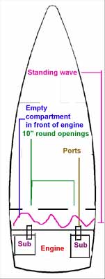
The standing wave and the boundary effects with in this compartment created strong cancellation zones directly in front of the 10 holes that I cut to let the sound through, and this basically killed the bass response. To remedy this I placed a simple barrier in the compartment that broke it up into uneven portions. This made any standing waves occur at a much higher frequency (outside the listening range). The reason that the portions where made uneven was to avoid the two chambers from resonating at an equal frequency creating a harmonic resonance.
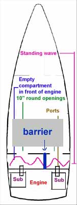
The result was an astounding average 13.5 db rise across a 35hz bandwidth (35-70hz). This is the difference between absolute success and failure. The reasons that most people try to avoid standing waves in car audio is due to a misunderstanding of what they are. In the event that a standing wave creates a node at the listening position it is sometimes absolutely necessary to kill it. Getting to know all of the effects of reflecting waves within your ride will help you achieve whatever you are looking for. However, as for SPL I would not depend on predicting it due to the unpredictable nature of multiple resonant and diaphragmatic walls that form the reflectors in your vehicle. Understanding standing waves, taking precautions to avoid unwanted waves and recognizing the existence of a standing wave after testing is the key. From your diagram of your testing area it looks like you might get some reflections off of the left side. I suggest testing your sub in a well sealed enclosure of a known size (actual size doesnt matter). Then model the enclosure by software and get a good idea of what slope the sub will roll of at on the low end. Calculate the frequency that is of equal size of the distance to any reflector in your test area. Then compare your software predictions to the ground plane test. You will be able to easily spot any effects that reflectors in your test area might produce. The reason that it is important to actually conduct this test is so that you can limit any doubt about the accuracies of your software predictions and manufacturing tolerances of your sub (25% is not out of the norm). The effects of a reflecting surface will cause a sudden bump in the response. This is why I suggest a sealed enclosure. The low end roll off should be smooth regardless of the slope or frequency at which it occurs.
Also the only way that I know of augmenting the resonant frequency of a car involves drastically reducing the boundary gain. Not what you want to do For SPL. If you are willing to settle for very loud (even abnormally loud) but not ultimate SPL you can design your box to perform at a lower frequency range. You will not get the gain of the resonant frequency but you will get a gain that increases as frequency drops. Personally, I like this effect because it gives you a real kick in the butt without destroying the quality of your bass. Generally speaking and heavily depending on the design of the driver.
Posted By: wormy
Date Posted: June 18, 2007 at 1:45 PM
-------------
...typically, I just run whatever I randomly pick up off the floor.
1995 Ford Ranger Supercab
MECA member
Team CSS
Posted By: wormy
Date Posted: June 20, 2007 at 2:03 AM
-------------
...typically, I just run whatever I randomly pick up off the floor.
1995 Ford Ranger Supercab
MECA member
Team CSS
Posted By: hustlin247
Date Posted: June 20, 2007 at 11:35 AM
jmelton86 wrote:
Vehicles' panels, as any part of the vehicle really, has its own fs. This is due to the size, the way it's held in place, where its held in place, along with innumerable(sp?) other factors that affect the particular piece. Now, the vehicle is actually louder at one frequency than others -just where the panels hit 'common ground' with each other. This is the actual fs of the vehicle.
What I want to know is would building a ported box tuned to the vehicle fs be the best way of getting a comp-worthy vehicle?
Also, since to have the front and rear waves hit the mic at the same time is optimum for comps, how would one going about this? -what this thread was started for, I think.
I once had an Alpine head unit that allowed you to enter the distance in inches of each speaker to a listening point that you defined in order to time them all.
I'll try to come up with a model number.
-------------
'94 Ford Explorer / Kenwood KVT-815DVD / RF Power T1682C 6x8 (all doors) / RF Power T10001 / 12" Kicker L5 (x4) / Optima Yellow Top Battery
Posted By: jmelton86
Date Posted: June 20, 2007 at 7:03 PM
hustlin247, I know of what you speak. The TimeCorrection function is in my Alpine HU, as well as others. Model # CDA-9830. It is very helpful. However, great concentration is needed to get it even close.
But, my 9830 only has it for the 4 channels, not the sub. This, still, isn't what I was talking about. I was refering to how a ported box is designed, for SPL only, to allow the waves coming off of the rear of the subwoofer cone to reach the mic at the same time as the front ones. This allows for greater SPL #'s with way less power.
I heard about this concept from reading about some guy, a mathmatician whose name escapes me, who built a wall for 4 PlanetAudio 15's in a Honda for a guy. He incorporated the vehicle fs as well as the distance from the pillars the box was to be. I'm sure other factors were needed. -The owner was going against a rival with a similar setup (4 15's in a wall) in a similar vehicle. He was using less than half the power, and hit a higher #.
-------------
2013 Kia Rio -90a alternator
DDX470HD GTO14001 GTO1014D (x3)
Big3 in 1/0G
1/0G to GTO14001
Posted By: speakermakers
Date Posted: June 20, 2007 at 9:47 PM
Although adding delay to a single sub in a multi sub system though can make or break standing waves and other phenomenon that exists do to interaction between the subs.
Decks with time alignment on board is a great thing. But beware! This feature is nearly useless if the deck dose not let you manually adjust this feature increment by increment. Many do not. Also beware that many decks like my Eclipse 8455 do not have time alignment on the sub channels. I use a stand alone processor for this and still love my deck due to its extreme value in other areas.
Posted By: wormy
Date Posted: June 25, 2007 at 6:33 PM
Hmmm...things I want to say to jmelton86...lol.
Time Correction.
Not what we're talking about. Think with me in simple terms everyone, just to make sure you understand where I am coming from. ONE speaker. We need to keep this simple. Time correction at no point will affect the wave coming off of the from of the speaker as the velocity of the front wave will be nearly the same as that of the rear. The only reason why I say nearly is because the temparature from one side of the vehicle to the other may be different enough to change the velocity of the waves to such a degree as might allow the front wave to reach the point of destination before the second wave. Time correction only affects the difference in time between a signal being sent to speaker A as opposed to speaker B. Meaning, it is only a time delay for the signal containing the information of the music between the different channels. The left channel might get the signal 0.01 seconds before the right channel.
Control of the strongest wave.
Definately the topic at hand. Feel free to continue discussing this topic further so that I might pick up new things to research.
-------------
...typically, I just run whatever I randomly pick up off the floor.
1995 Ford Ranger Supercab
MECA member
Team CSS
Posted By: jmelton86
Date Posted: June 25, 2007 at 6:53 PM
I wrote: But, my 9830 only has it for the 4 channels, not the sub. This, still, isn't what I was talking about. I was refering to how a ported box is designed, for SPL only, to allow the waves coming off of the rear of the subwoofer cone to reach the mic at the same time as the front ones. This allows for greater SPL #'s with way less power.
-First two sentences, mostly. I was refering to what hustlin247 posted before that. About how he knows of an Alpine HU with time-correction, of which was not being talked about.
-------------
2013 Kia Rio -90a alternator
DDX470HD GTO14001 GTO1014D (x3)
Big3 in 1/0G
1/0G to GTO14001
Posted By: wormy
Date Posted: June 26, 2007 at 12:37 PM
sometimes I wish I could edit my posts...lol.
Okay...so I realize now that you weren't talking about time-correction. Sorry.
I don't think you can change the time that the front wave can reach without changing temparature, because the velocity of the wave is only changed by temparature. The only way to get a further back wave to reach the front before or at the same time as another is to change the temparature of the areas in which the waves travel appropriately. I'd honestly prefer just to deal with the single strongest wave and eliminate the other.
Glad to see we're on the same page...lol.
-------------
...typically, I just run whatever I randomly pick up off the floor.
1995 Ford Ranger Supercab
MECA member
Team CSS
Posted By: wormy
Date Posted: June 26, 2007 at 12:38 PM
-------------
...typically, I just run whatever I randomly pick up off the floor.
1995 Ford Ranger Supercab
MECA member
Team CSS
Posted By: jmelton86
Date Posted: June 26, 2007 at 6:38 PM
-------------
2013 Kia Rio -90a alternator
DDX470HD GTO14001 GTO1014D (x3)
Big3 in 1/0G
1/0G to GTO14001
Posted By: speakermakers
Date Posted: June 27, 2007 at 2:51 AM