fix two fried amps?
Printed From: the12volt.com
Forum Name: Car Audio
Forum Discription: Car Stereos, Amplifiers, Crossovers, Processors, Speakers, Subwoofers, etc.
URL: https://www.the12volt.com/installbay/forum_posts.asp?tid=99581
Printed Date: April 09, 2026 at 2:07 AM
Topic: fix two fried amps?
Posted By: importhunter
Subject: fix two fried amps?
Date Posted: December 02, 2007 at 11:15 AM
First one is a rockford 401s 1200w punch amp, its the gun metal style. The power touched the ground. I have another one to match so I want to keep this one. No visual burn marks on anything.  This one is out of a MTX thunderform. the status LED comes on and is green but it does not put out anything. I am not sure what happened to it.    these are not is the same vehicle.
Replies:
Posted By: importhunter
Date Posted: December 02, 2007 at 11:16 AM
I figured I would post the pics large so you guys might see something I cant.
Posted By: i am an idiot
Date Posted: December 02, 2007 at 1:05 PM
Power touching ground should have blown the fuse at your battery. It should not have hurt the amp. Do you have an ohm meter to do a little troubleshooting?
Posted By: importhunter
Date Posted: December 02, 2007 at 1:47 PM
Yeah I have alot of testing stuff just not sure where to start or what I am looking for since there is no visual damage.
Posted By: Alpine Guy
Date Posted: December 02, 2007 at 2:03 PM
With the rockford i looks like it has to amp stages, on on each side, so both amp stages should be identical, take your ohm meter and test the resistance on those mosfets and compare them to the mosfet resistance on the other side, check all 3 resistance combination on each fet, if they are off by quite a bit then you will for sure need to get that amp repaired.
Thats a start, it's going to be hard to repair that amp if you don't have much repair skills, since it uses those micro resistors, I would recommend sending them to a local technologist.
-------------
2003 Chevy Avalanche,Eclipse CD7000,Morel Elate 5,Adire Extremis,Alpine PDX-4.150, 15" TC-3000, 2 Alpine PDX-1.1000, 470Amp HO Alt.
Posted By: i am an idiot
Date Posted: December 02, 2007 at 2:16 PM
If it were me I would put the amp back in the vehicle and verify you have 12 volts on power and remote. The 2 transistors at the bottom left and bottom right are the power supply transistors. Set you ohm meter to the Diode test function. Touch and hold one lead to the metal tab of one of the transistors and then touch the other lead to one of the outside legs. Then touch to the other outside leg. Do this with all 4 transistors. None of them should read below .300 after leaving the leads there for 10 seconds or so. If any of them read below that let me know what it reads.
Posted By: importhunter
Date Posted: December 02, 2007 at 6:20 PM
can you show me exactly where? I tested the 330uf caps and they all read 805.
Posted By: importhunter
Date Posted: December 02, 2007 at 6:23 PM
The RF led doesnt come on.
Posted By: importhunter
Date Posted: December 02, 2007 at 6:28 PM
also while I am on the diode setting I put the ground on the ground on the amp and the + on the + and I get a reading of 804
Posted By: i am an idiot
Date Posted: December 02, 2007 at 7:21 PM
Notice on the bottom left of your picture, on the Green strip that all of the 3 legged thingys are mounted to. There are 2 designations ON THE GREEN STRIP One is TC7 and the other is TC8 Those are the 2 power supply transistors on that side. On the lower right side of your picture the green strip has 2 other labels one is TC15 and the other is TC16. These are the 2 transistors on the right side.
Posted By: importhunter
Date Posted: December 04, 2007 at 7:43 AM
both on the right side read 809. The ones on the left read 694 and 001 for the top one and 828 and 201 for the bottom one.
Posted By: importhunter
Date Posted: December 05, 2007 at 5:29 PM
any idea?
Posted By: i am an idiot
Date Posted: December 06, 2007 at 3:09 AM
Yes the power supply of your amp has failed. From the numbers you gave me one of the transistors is shorted. However in order to repair this all 4 need to be replaced. And probably several surface mount components. This is not an easy first repair. You will need a butane powered torch/soldering iron available from Radio Shack, at a price of 19.99. You will have to go somewhere else to buy some Butane for the iron. Before you order any parts for this project you will need to check the rest of the 3 legged thingys the same way you checked these 4 components. If anything reads below .300 after the probe is held on them for a few seconds, Post the part number and the reading.
Posted By: importhunter
Date Posted: December 06, 2007 at 7:43 AM
Can I upgrade the transistors to a higher wattage or something while I am in here? So far all I have tested is the Mosfet sides and abour 12 of them are toast. Does EVERYTING need to read above .300? I found the Mosfet transistors. Its P/N irf9640 Is this site a good place to get them from cause I need 16 and their .75 a piece. https://www.futurlec.com/TransMosIRF.shtml
Posted By: i am an idiot
Date Posted: December 07, 2007 at 8:39 PM
The Rockford amp in the picture should have only 4 IRF9640s. What are the part numbers of the power supply transistors?
Posted By: importhunter
Date Posted: December 07, 2007 at 11:58 PM
Posted By: i am an idiot
Date Posted: December 08, 2007 at 4:27 AM
A 9640 will not be a suitable upgrade in your situation. They are a higher voltage but lower current version of the 9540. You can upgrade the power supply transistors (The MTP 50N06s) with an IRF-3205. The 50N06 is rated at 50 amps and the 3205 is rated at 85. If the surface mount resistors that feed the leftmost leg of the 50N06s are not 20 Ohms they will need to be changed. After re-checking your original picture the resistors appear to be bad. Even if you do not upgrade to the 3205s they will need to be replaced. They are probably 47 or 100 Ohms. Chances are you will have to replace at least 2 surface mount transistors and several surface mount resistors. Before you go and order some parts we really need to make sure we can get the transistors unmounted from the green strip that they are mounted to.
Posted By: importhunter
Date Posted: December 08, 2007 at 7:35 AM
I can for sure get them off of the green strip. Where are the resistors you are talking about?
Posted By: i am an idiot
Date Posted: December 08, 2007 at 8:48 AM
The resistor that is connected to the Left Leg of each power supply transistor. Follow the trace from the leg to the next component. How exactly do you plan to remove the transistors from the green strip?
Posted By: importhunter
Date Posted: December 08, 2007 at 4:01 PM
Ahh the tiny black ones. Those will be a challenge.
I am going to heat up the metal circle above the plastic casing then just heat up each leg and blow out the solder with compressed air. Is that the right way?
Posted By: i am an idiot
Date Posted: December 08, 2007 at 8:30 PM
Heating up the metal tab is the hard way. An air compressor is the very messy way. If you insist on heating the tab, you will need at least a 90 watt weller iron. It is orange in color and has a 3/8 inch wide tip on it with a flat surface. I forget the model number but I am sure you can find one. It will of course need to be unmounted from the heat sink.
Posted By: importhunter
Date Posted: December 09, 2007 at 12:06 AM
Whats the easy way? also are those little ones that say 101 the right resistors? They are coming off of what i am assuming is the left leg of th transistor. Where can i buy the tiny resistors? I tried to google "resistor 101" but I kept getting classes. Any links?
Posted By: i am an idiot
Date Posted: December 09, 2007 at 6:05 AM
Yes the 101 resistor is the one I am talking about. It is a 100 ohm. It works just like a color coded resistor. First digit is first number, second digit is second number. Third digit is the number of Zeros you put behind the first 2 digits. 1 0 with a 0 behind it. 100 Ohms. The easy way is with the Butane Torch mentioned earlier. I will get you a size and source for the surface mount resistors and post later.
Posted By: importhunter
Date Posted: December 10, 2007 at 9:07 PM
Cool! Thanks, do you think anything else will be fried?
Posted By: importhunter
Date Posted: December 10, 2007 at 9:55 PM

There are all the ones that read above 300.
Posted By: i am an idiot
Date Posted: December 11, 2007 at 4:00 PM
How do you have 2 readings on some and 3 on others? If you are putting one lead on the tab of the transistor and then reading to each leg, The tab is directly connected to the middle leg. Hence the .000 reading on TC6. If this is how you are reading them there is a problem with TC13. The middle reading there should be .000 also. Chances are the only thing other than the power supply transistors and the gate resistors mentioned earlier that will need to be replaced are 2 of the 4 surface mount transistors that are fed by pins 9 and 10 of the 594 IC. Directly north of the transformer there are 4 transistors mounted in a row. You will need to change the 2 that have the top connection connected to ground. I will get you a part number for them tomorrow. I need to get you the number for the resistors too.
Posted By: importhunter
Date Posted: December 11, 2007 at 8:59 PM
are you talking about the black cylinder things with 3 legs that are between all the Mosfet transistors?
Posted By: i am an idiot
Date Posted: December 13, 2007 at 6:49 AM
The transformer is the big coil of wire wrapped around the doughnut shaped ceramic coated core. There are red and green wires wrapped around it. The red and green wires then go to a location on the board near the mosfets. Treat your picture as a map. directly North of the transformer there are 4 surface mount transistors all lined up in a row. Ok not directly north, but maybe at 355 Degrees.
Posted By: importhunter
Date Posted: December 13, 2007 at 9:16 PM
Ahh Ok I see them, which ones will they be? The set on the left or right? 2 of them say 1am and a sideways Y, and the other 2 say `2a and a sidways N (not a Z)
Posted By: i am an idiot
Date Posted: December 15, 2007 at 6:18 PM
As stated above, the 2 transistors that have the middle connection grounded. The other 2 have their middle connection at 12 volts.
Posted By: i am an idiot
Date Posted: December 15, 2007 at 7:35 PM
Posted By: importhunter
Date Posted: December 15, 2007 at 10:53 PM
Wait, its only gonna cost me like $5.00 to fix this? Wow! Thats CHEAP! I will put some money in the bank on Friday then order them! Thank you! is there anything else to look at? Do I need to worry about the other transistors? or should I just replace the 4 on the power supply side?
Posted By: i am an idiot
Date Posted: December 16, 2007 at 10:19 PM
You still need to get the power supply transistor. Future has them.
Posted By: importhunter
Date Posted: December 16, 2007 at 10:54 PM
I checked Futureelectronics and I couldnt find them. Here are some I did find though. Which of these 2 do I want?
Here is the one that is in it now: the MTP50N06V
https://www.ortodoxism.ro/datasheets/on_semiconductor/MTP50N06V-D.PDF
Here is the IRF3205
https://www.irf.com/product-info/datasheets/data/irf3205.pdf
Or do i want them both?
Posted By: importhunter
Date Posted: December 16, 2007 at 11:01 PM
https://www.futurlec.com/TransMosIRF.shtml
is this the place?
Posted By: i am an idiot
Date Posted: December 17, 2007 at 3:52 AM
The 3205s are a better choice, but you will have to get 20 ohm gate resistors instead of the 100 ohm. Yes that is the place.
Posted By: importhunter
Date Posted: December 17, 2007 at 5:54 PM
Is this going to boost the output of my amp? Cause I have another one that is going to the same sub.
Posted By: i am an idiot
Date Posted: December 17, 2007 at 8:03 PM
No it is not going to boost the output. It will make the power supply less likely to go out but will not increase theoutput.
Posted By: importhunter
Date Posted: December 17, 2007 at 8:24 PM
Sweet! Thank you so much for your help! I will order everything this Friday. I will verify everything on here before I put it on. Do you know anything about the other amp? Its not that important really.
Posted By: importhunter
Date Posted: December 17, 2007 at 10:12 PM
Ok, I ordered 40, 100 ohm resistors and 10 transistors and 6 MTP50N06V's.
Posted By: i am an idiot
Date Posted: December 19, 2007 at 9:36 PM
I have worked on one of those MTX amps, it has been a long time. Is the status LED green for power and red for protect? You need to check the Transistors and see if any are shorted.
Posted By: importhunter
Date Posted: December 22, 2007 at 11:52 PM
I will wait till I fix this one before I get to the mtx but yes thats right.
Ok, I soldered in the 2 mosfet power supplies on the left and right. I also soldered in the 4 up top. Now I think Mouser sent me the wrong resistors, the ones on the amp read "101". the ones from mouser are "1000". Can you give me a direct link to them? These are the only thing I lack.
Posted By: i am an idiot
Date Posted: December 23, 2007 at 12:25 AM
Use an ohm meter to check them. They may be 100 ohms. The last number may be the multiplier. It would be 100 with 0 0's at the end.
Posted By: importhunter
Date Posted: December 24, 2007 at 11:50 AM
Cool, for some reason I didnt even think of that, lol
Ok so I have everything soldered in. I have the bottom 2 (on each side) mosfets, the 100ohm resistors (2 on each side) and the 4 transistors located on the north side 355*. How should I test this? Also I tested the mosfets and I got a reading of 455+ on them. Is that normal?
Posted By: i am an idiot
Date Posted: December 24, 2007 at 2:23 PM
You replaced all 4 of the transistors north of the transformer? Do not turn the amp on untill you answer the preceeding question.
Posted By: importhunter
Date Posted: December 24, 2007 at 3:48 PM
 I replaced all 4 of these.
Posted By: i am an idiot
Date Posted: December 24, 2007 at 4:14 PM
Do not try to turn the amp on. You were supposed to change only 2 of them. There are 2 NPNs and 2 PNP transistors. The NPNs rarely fail like 1 in every 100. The PNP transistors fail about 90 out of 100 times. When I go back to work Wednesday I will get you a part number so you can order the right ones.
Posted By: importhunter
Date Posted: December 24, 2007 at 4:42 PM
I still have them! Where do they go?
Posted By: importhunter
Date Posted: December 24, 2007 at 4:46 PM
They are labeled from left to right: q4,q5,q1,q2
Posted By: i am an idiot
Date Posted: December 24, 2007 at 4:46 PM
You will have to re-read the thread and see which of the 2 you were supposed to replace. Then you will have to figure out which of the 2 went in the spot you were not supposed to replace. You will have to use a meter and figure out the 2 that are opposite of the ones that you bought.
Posted By: i am an idiot
Date Posted: December 24, 2007 at 4:54 PM
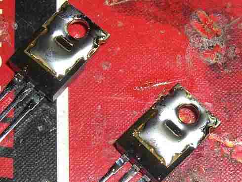
How did you remove and resolder the transistors off of the green strip? I had taken several pictures to assist you in that. Could you take pictures of the new power supply trannsistors.
Posted By: importhunter
Date Posted: December 24, 2007 at 5:02 PM
 I used a soldering iron torch. The one you told me about.
Posted By: i am an idiot
Date Posted: December 24, 2007 at 5:15 PM
You need to make sure that they are all flat on the strip. Did you tin the back of the transistors and put solder on the strip after you removed the transistors? The extra solder ensures a good bond to the strip. The solder is their only lifeline to the heat sink.
Posted By: importhunter
Date Posted: December 24, 2007 at 5:19 PM
yeah I put more solder underneath. They are on there pretty good. I found the 2 that I removed by accident and put them back. If their not the right ones by chance, what would happen?
Posted By: i am an idiot
Date Posted: December 24, 2007 at 6:07 PM
The first thing you need to do is make sure the transistors that you are not changing remain soldered to the strip. This is achieved using a binder clip available at Office Depot. 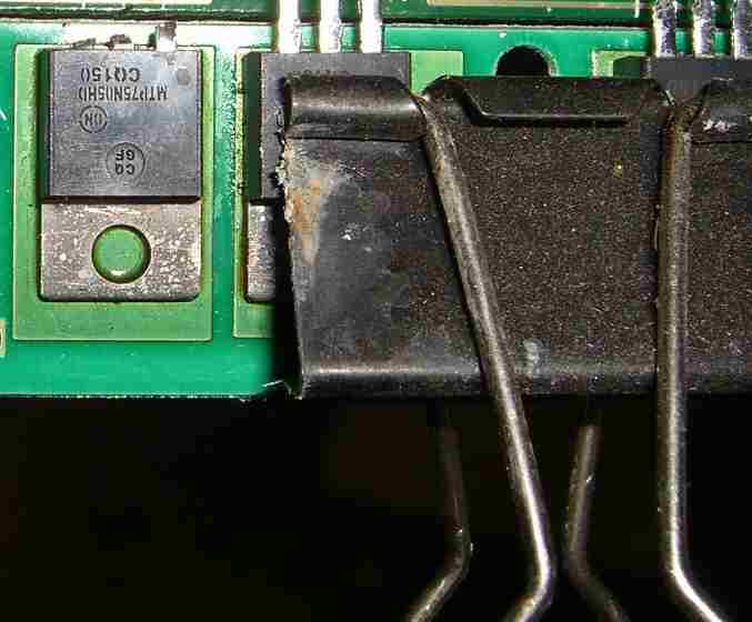
The easiest way to remove the transistor is to cut the legs off of it, so when it heats up it will be easy to just knock it off of the strip. 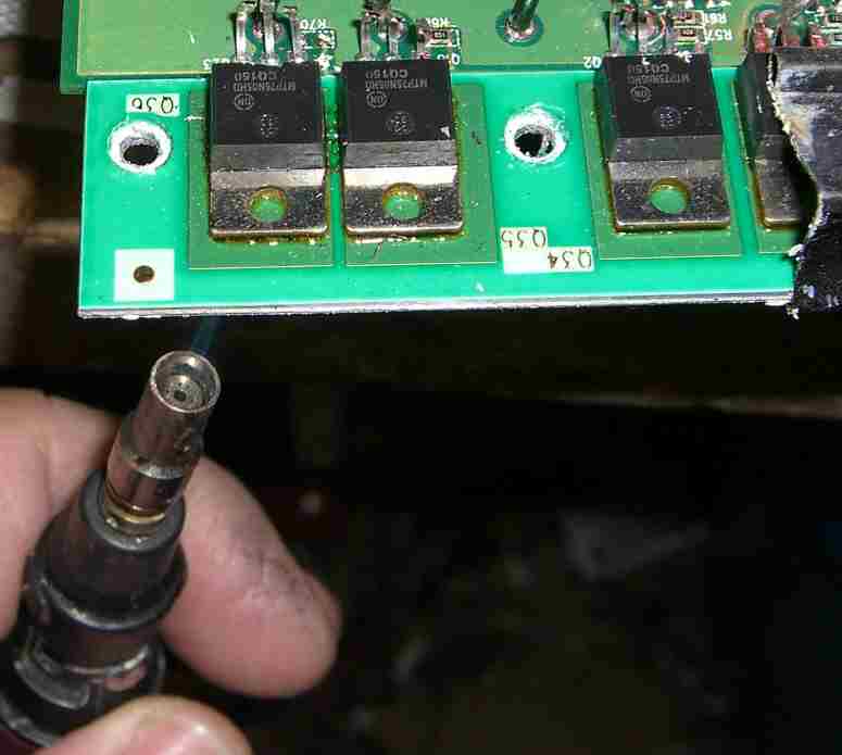
I forgot a step. First and foremost you need to use a razor blade and remove all of the compound from the bottom of the strip. It burns really bad if it drips on your finger while applying the heat from the torch. 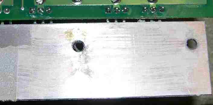
After removing the transistors you need to apply an a thick layer of solder to the top of the strip. 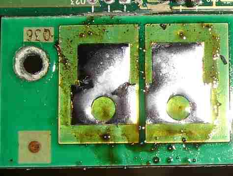
Then we need to apply a healthy layer of solder to the back of the new transistors. 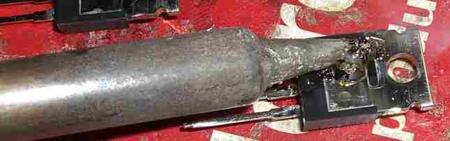
Posted By: i am an idiot
Date Posted: December 24, 2007 at 6:32 PM
The next step would be to remove the legs of the transistors from the board, then remove the solder from the holes in the board. Then bend the legs of the new transistors and place through holes in the board. You have to align the transistor so that it is centered over the pad that it is to be soldered to. I had pictures of the ViseGrip brand C clamp that I use, but I can not find it. When it heats up enough to melt the solder on the strip and the back of the transistor I use the C clamp to hold the strip and the transistor firmly together untill the solder cools. 30 seconds to be safe. After soldering the first one down you need to use another binder clip to keep that one down while heating the second.
Posted By: importhunter
Date Posted: December 24, 2007 at 7:59 PM
Yeah, I used the torch side to heat up the metal tab, then held it on with a screwdriver while it was cooling.
Posted By: importhunter
Date Posted: December 24, 2007 at 8:03 PM
I also, am upgrading from the white grease to the silver stuff from www.articfox.com it has silver in it and should transfer the heat better.
Posted By: i am an idiot
Date Posted: December 24, 2007 at 8:20 PM
If you heated the tab of the transistor, you need to check the transistors to see if they are shorted.
Posted By: importhunter
Date Posted: December 24, 2007 at 8:49 PM
if they are they will read below .300 right?
Posted By: importhunter
Date Posted: December 24, 2007 at 8:53 PM
also i tested the ground and positive and I am not getting a reading. so thats a good thing right?
Posted By: i am an idiot
Date Posted: December 24, 2007 at 9:07 PM
Right as long as they are not reading below .300 they are fine.
Posted By: importhunter
Date Posted: December 24, 2007 at 10:10 PM
sweet, so am I ok to wire it up or should I test some other stuff?
Posted By: i am an idiot
Date Posted: December 24, 2007 at 10:48 PM
Did you put the old surface mount transistors back in? If so I guess we are ready to test. This is very important. Put a 10 amp fuse in the power wire of the amp.
Posted By: importhunter
Date Posted: December 25, 2007 at 2:57 PM
It popped 2 of them.
Posted By: i am an idiot
Date Posted: December 25, 2007 at 5:27 PM
i am an idiot wrote:
Did you put the old surface mount transistors back in?
Posted By: i am an idiot
Date Posted: December 25, 2007 at 5:35 PM
Connect only the remote wire and the ground wire. Connect only the remote wire and the ground wire. Get a volt meter and connect the ground lead to ground. Put the meter on DC volts scale. With power to the remote wire, touch the positive lead of the meter to the left leg of one power supply transistor. Write down that reading. Then touch it to another power supply transistors left leg. Write that down too. Then do this for the transistors on the other side of the amp.
|
