Ice Ice Polo Robolop Design
Printed From: the12volt.comForum Name: Rides and Systems Gallery
Forum Discription: Show off your vehicles, systems, and installations.
URL: https://www.the12volt.com/installbay/forum_posts.asp?tid=132845
Printed Date: April 08, 2026 at 4:33 PM
Topic: Ice Ice Polo Robolop Design
Posted By: robolop
Subject: Ice Ice Polo Robolop Design
Date Posted: December 01, 2012 at 7:27 AM
Like I pronounced earlier in my BMW topic, we bought a new VW Polo.
This will be used for daily use, and most of the time, my wife will drive it. When we made the decision to buy a daily car, I had to make a promise that I wouldnt lower it, or put bigger wheels on it.
First of all, because she has troubles with her back, and for the rims
.it wont be long until shell drive up the sidewalk.
But as for the ice, she had no problems with me doing some adjustments, BUT there had to stay enough room in the trunk at all costs.
The Polo is a 1400 comfortline, with DSG, Airco, Assheating, Cruise Control en some other stuff.
Here a picture from the Polo, just delivered (still with the protective foil on)

I will take some more pictures once shes washed, but there not much to be seen. Its an original new car.
But maybe some carbon updates will happen, who will know
About the ICE, everything I need is already here.
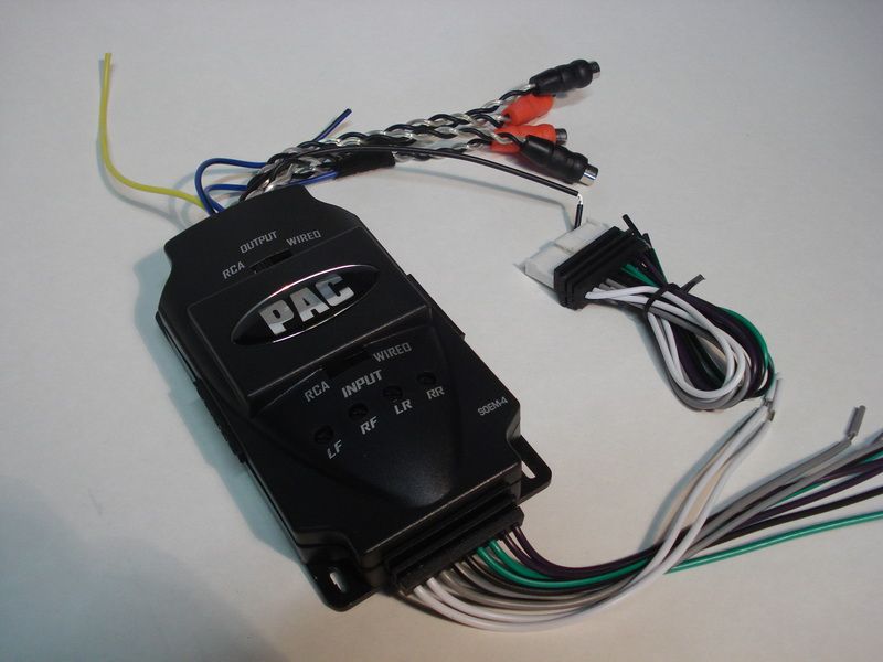
As for the radio, Im going to keep the original one, but since Im going to use an amp, Ive bought a Pac-Audio interface.
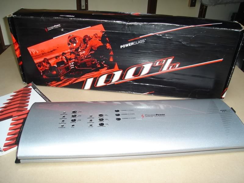
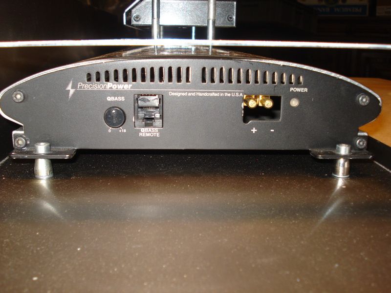
Im very happy I didnt sell the Precision Power amp I wanted to mount into the bimmer first.
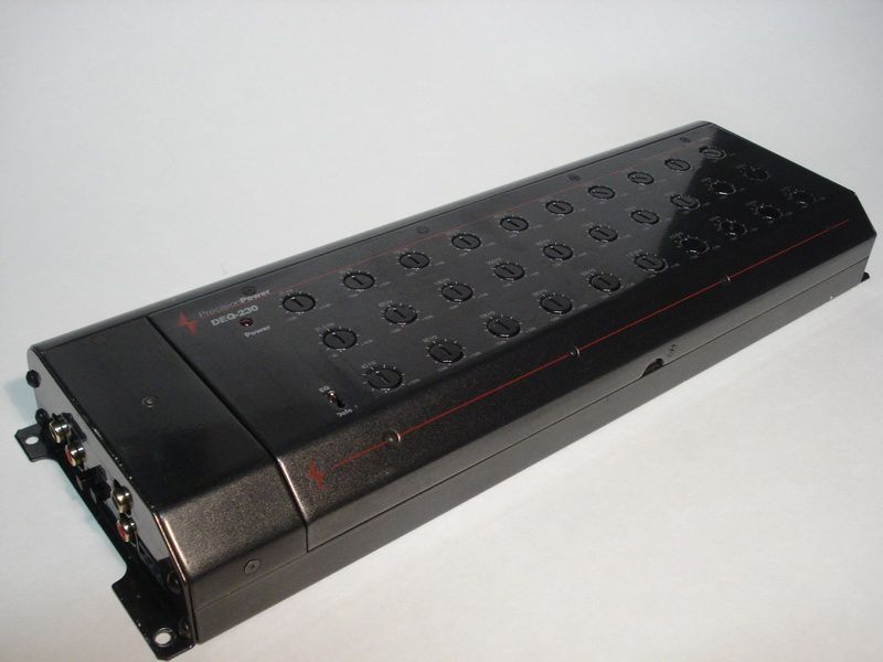
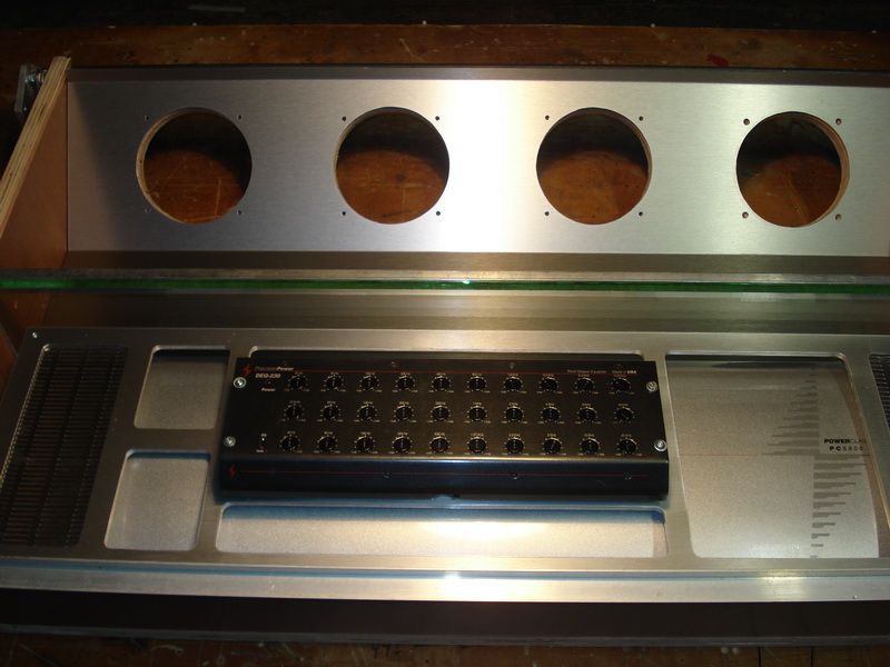
This PPI Deq 230 is a 30band equalizer. I can screw demount the front from this device, and with the longer cable (which is in the box), you can change the settings behind the wheel.
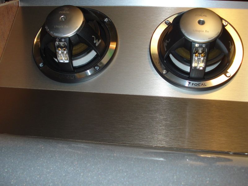
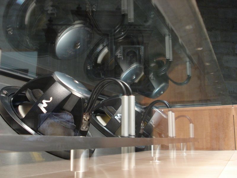
As for the Subwoofer, I chose for the 4 Focal Utopia 13ws , again
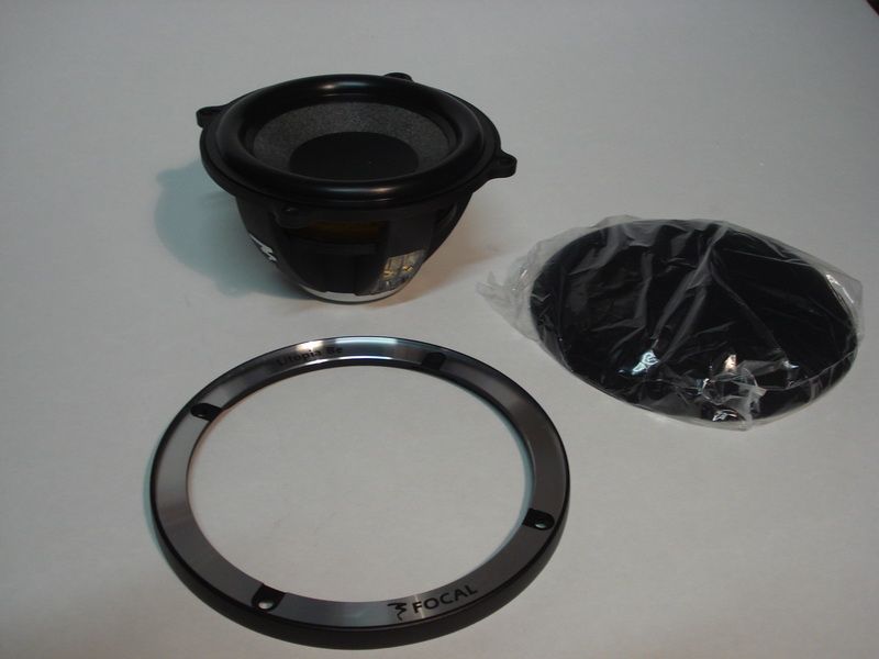
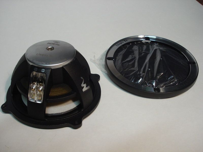
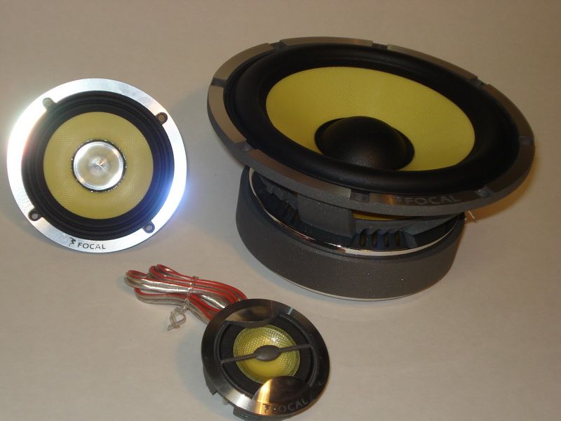
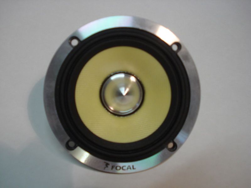
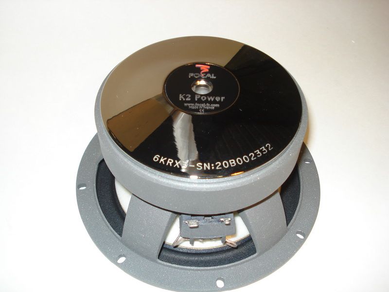
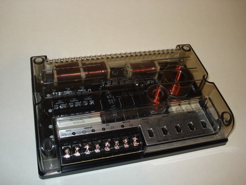
Also the front speakers will be Focals: the KrX3 series
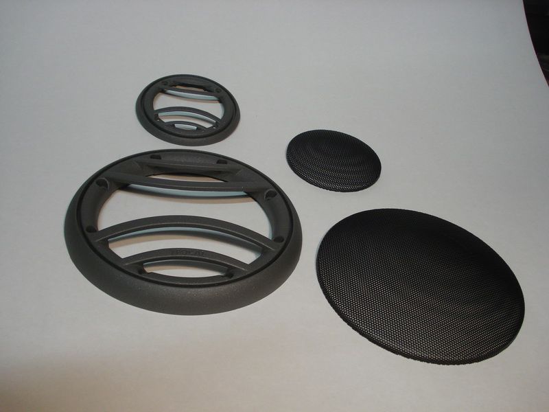
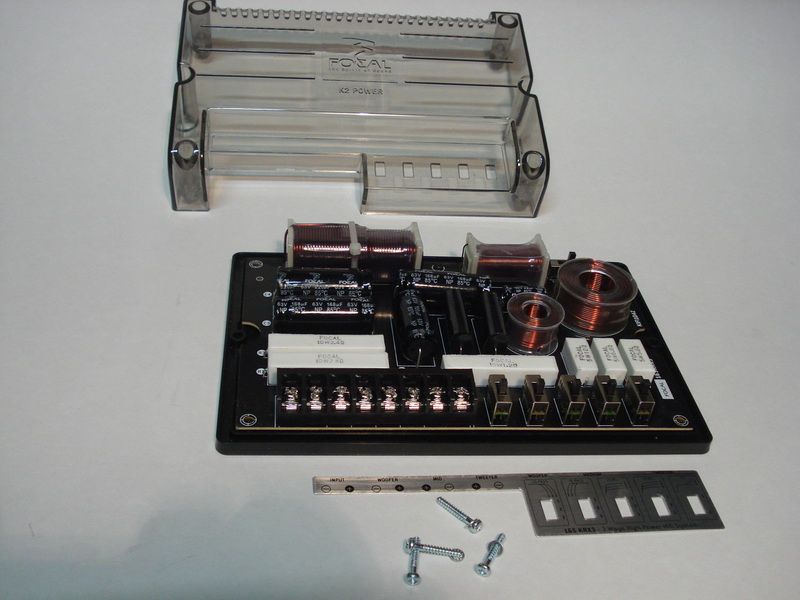
The filters.
And I also bought some cables and damping materials.

Itll take a while before Im going to begin on the install. First of all I want to finish up the mounting works from the new radio, in the bimmer.
Replies:
Posted By: robolop
Date Posted: December 22, 2012 at 7:12 PM
Finally , I started on the Polo.
I searched the net to find some pictures of what could be hiding behind the carpet, but then I decided to take it all out anyway. Sooner or later, this was inevitable.
The spare wheel, well, that has to stay. The intention is that this stays easily accessible, in case we need it.
In other words, Im going to make this install so that, in case of a flat tire, my wife can take the wheel easily and safely.
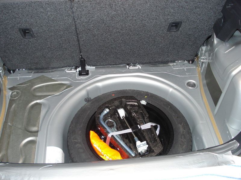
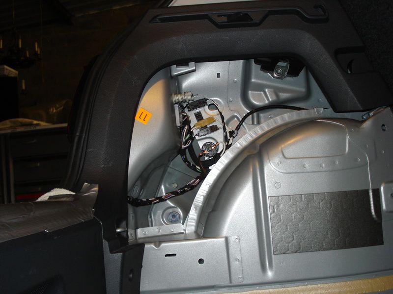
On the right side you can see theres not much that can be done here.
Its the place of the petrol tank, Id better not cut this open do I ?
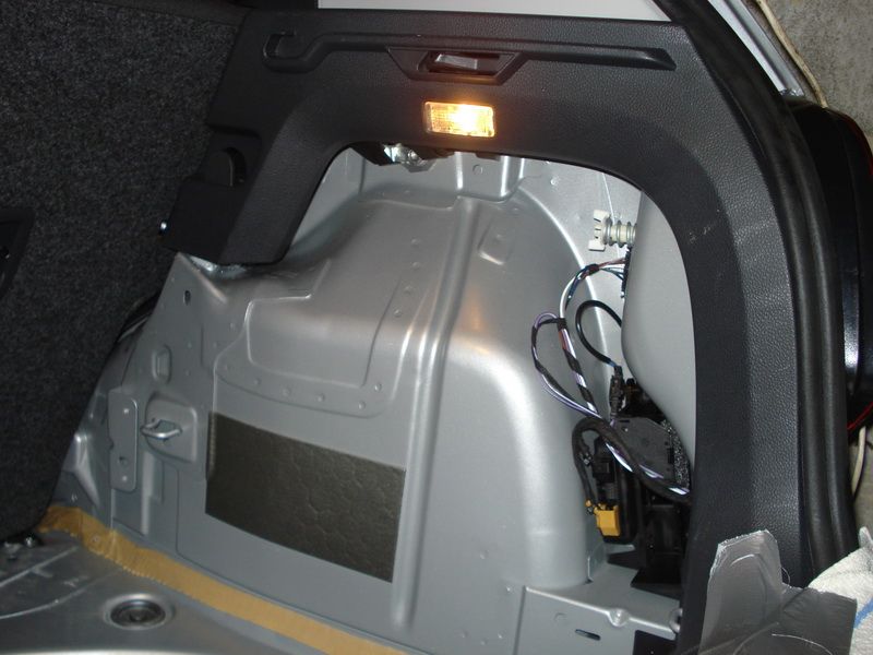
On the left side Ive got some more place to work with, but ho wand what, Im not quite sure.
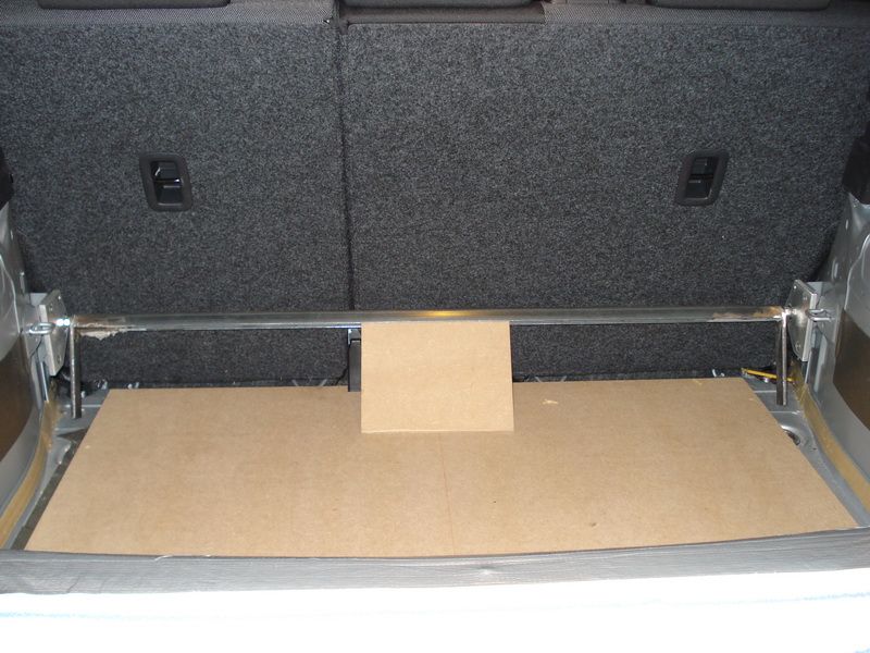
Then I placed a piece of MDF on the bottom, and looked what kind of emplacement is possible here.
I was at first a bit disappointed there wasnt enough room, cause in my case, you cant have enough room!
The intention is that the sub-box is placed against the rear seats. This will be in favor of the pressure, and also the looks will be much more pretty.
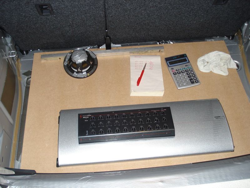
What I do know is that Ill place hem under diagonally. The view will be more spectacular and more beautiful, I think.
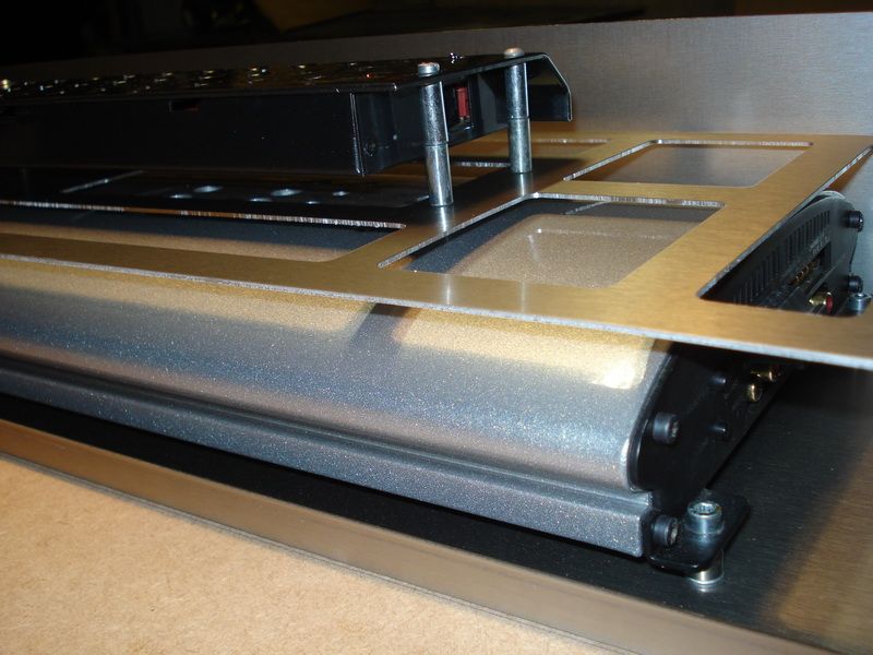
About the PPI (amplifierà), Ill have enough space to work away the cables in an appropriate way (L and R)
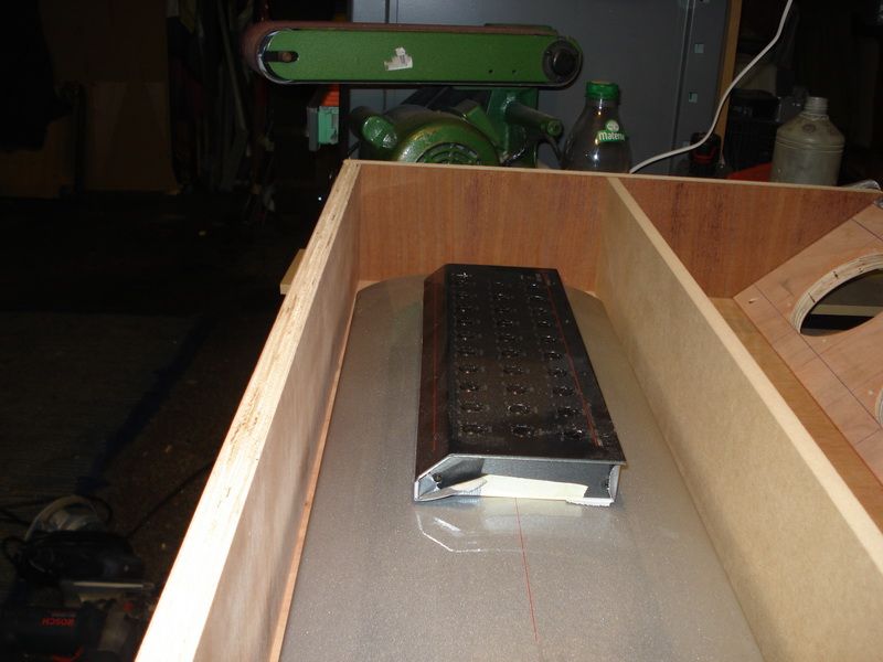
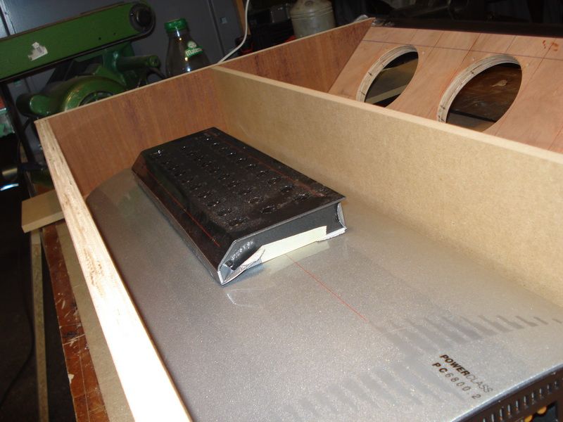
The equalizer is something else
Theres no room for that. You can see that I got it out of its housing, and I placed it ON the amplifier. It looked OK in my opinion.
But Im not there yet. First of all Im going to calculate how many liters are necessary for the subbox, the rest will turn out from its own.
Posted By: robolop
Date Posted: December 22, 2012 at 7:16 PM
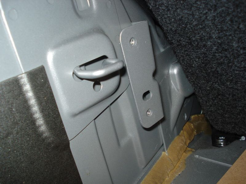
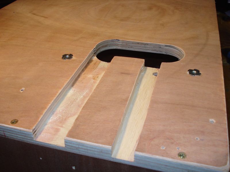
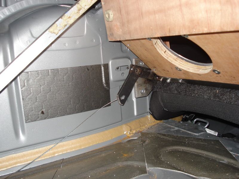
Because the floor needs to go all the way up before you can access the spare wheel, I had to make a hinge first.
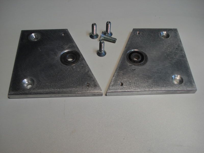
So I started to saw 2 little alu plates of 10mm thick.
Then I screwed them together and drilled 22mm holes in them.
These holes I oppressed with a lager of 22mm.
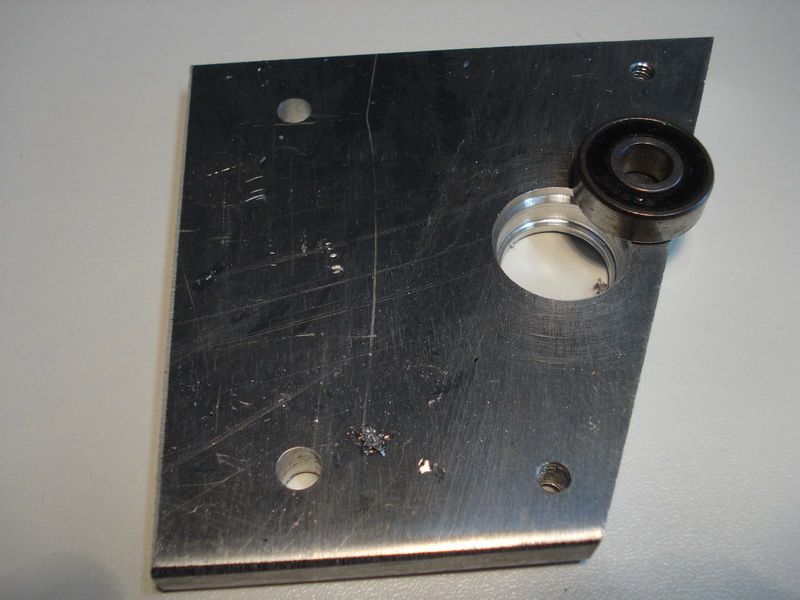
Oppress sound really professional, but I did it quite simple
As you can see, I placed the plate between the bench. After that I took a cap, which was a bit smaller than the lager, and then I turned it all together. Simple
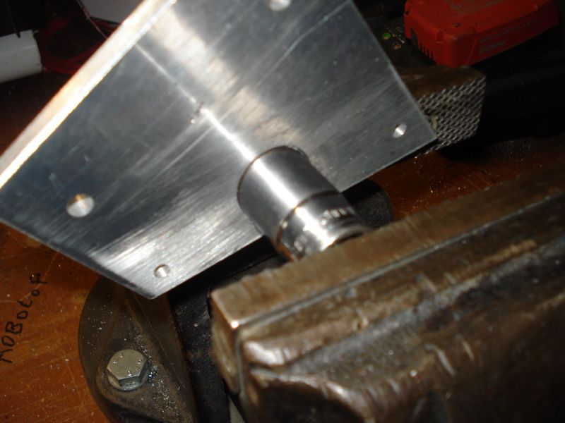
The result.
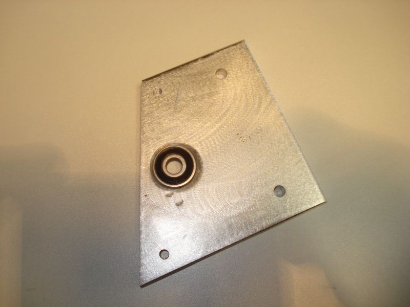
The alu plates will be mounted on a bracket, which is already in the polo (from the factory)
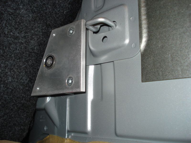
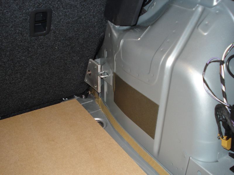
I screwed a bolt through the lager, an M8.
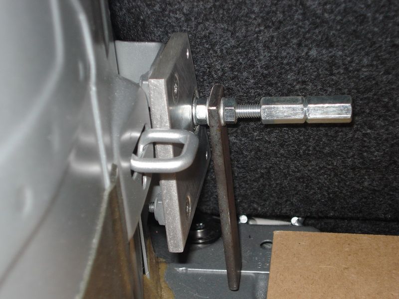
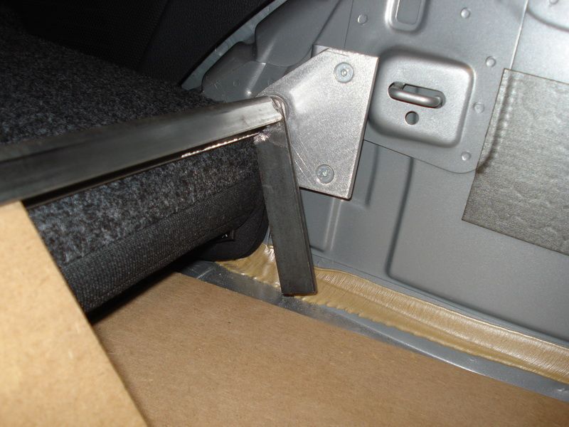
Once I did this on both sides, I connected these 2 with a U
This U is on the inside 18mm. There Ill place the wood in.
You can also see that the wood will be placed diagonally
Posted By: robolop
Date Posted: December 22, 2012 at 7:17 PM
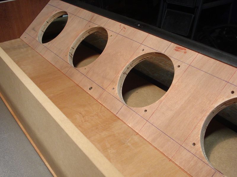
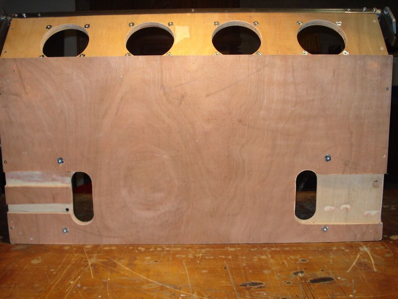
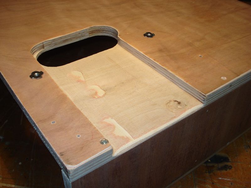
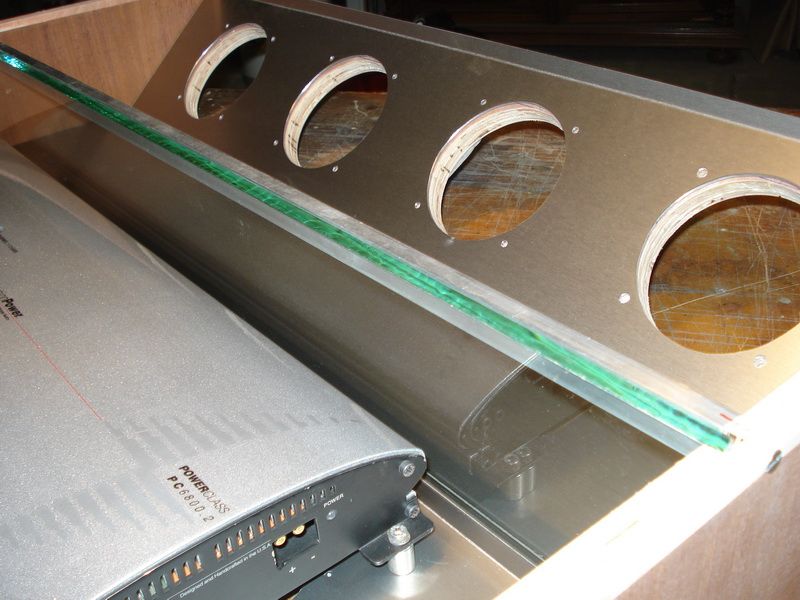
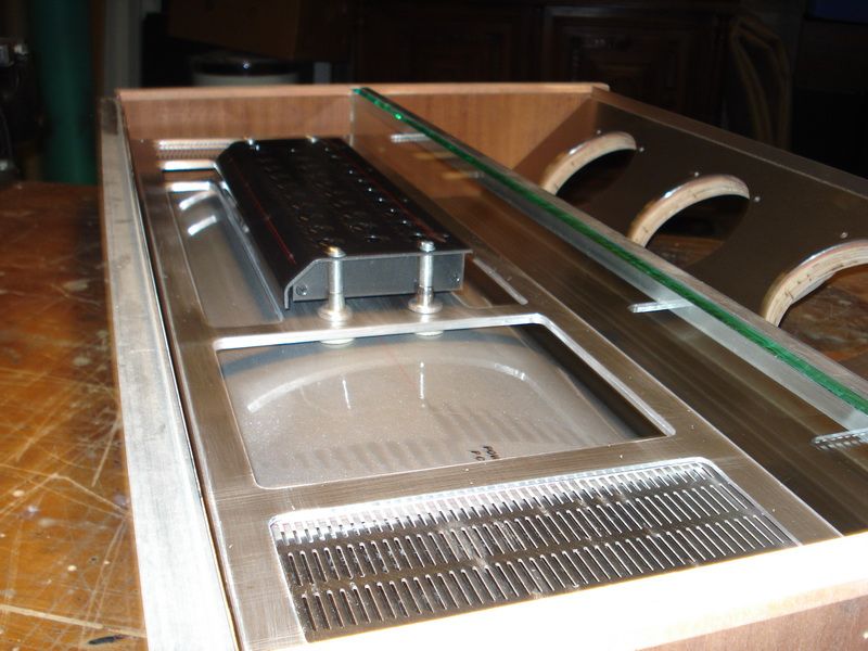
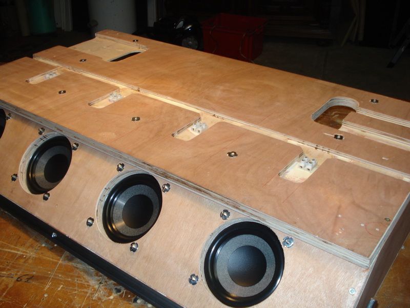
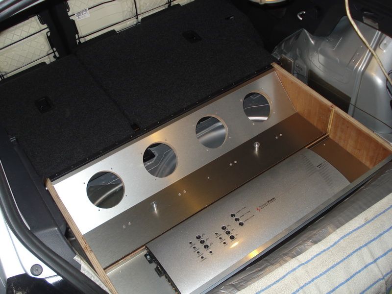
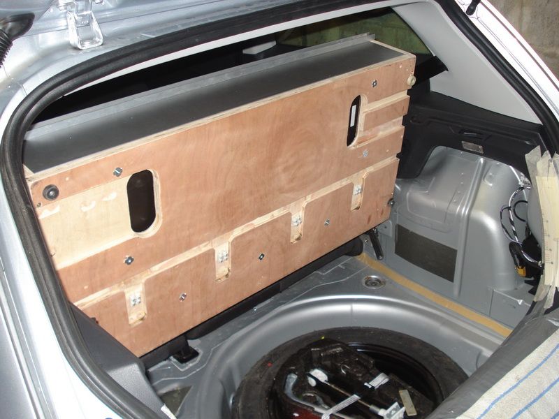
This will be the box, that will be mounted in the trunk.
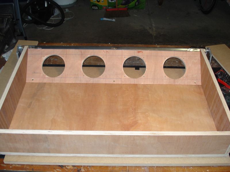
The 4 holes you see are for the Focal subs (4x13cm).
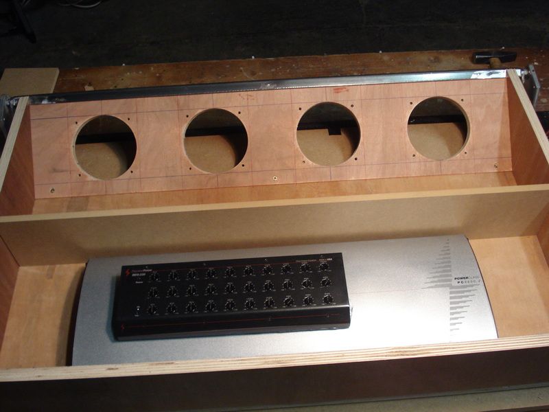
Another look at how big the sub-box will be.
Now you see a MDF-shelf that will part the sub-box from the amplifier area.
About the partition, Im thinking on some cool things, but Im not entirely sure yet
First I had the idea to work in the equalizer in one of the sun-blinders on the seiling, but they were too big for it. Its a pitty, cause I liked the idea myself.
Now Ive been working on the amplifier, and the more I see it, the more it grows on me.
Ill have to make a new sort of high-tec bracket, but that shouldnt be a problem I guess.
Here you can see its possible that I raise the equalizer a couple of more cms, and that too I liked!
Posted By: robolop
Date Posted: December 22, 2012 at 7:18 PM
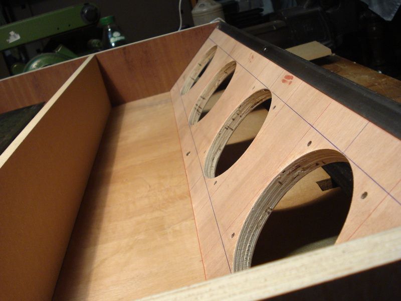
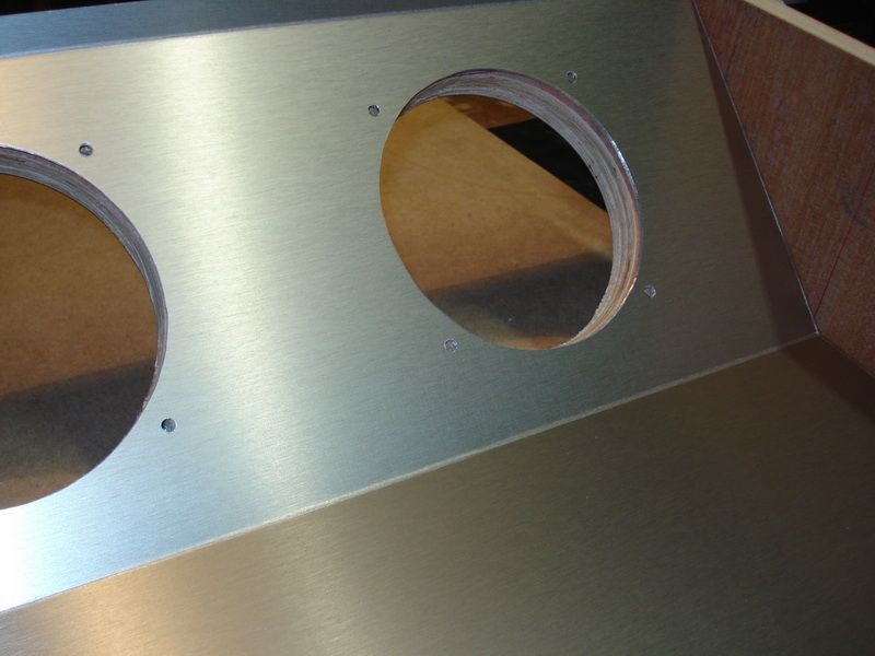
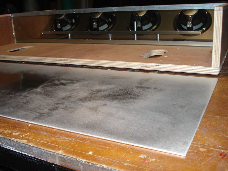
As for the finishing inside the box, I chose 2mm thick aluminium.
I also let some folding work done, which is strong.
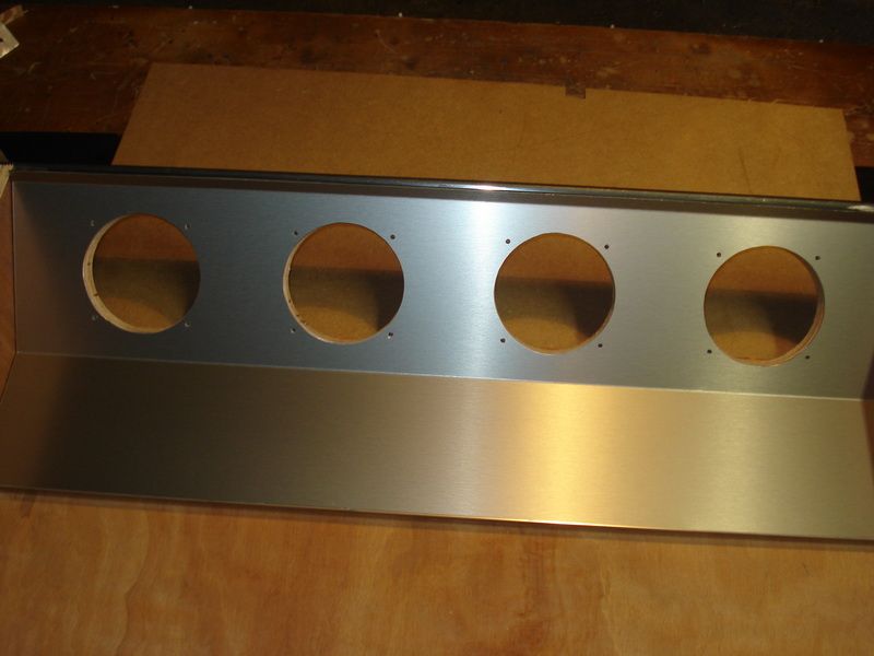
Milled out the holes for the subwoofers.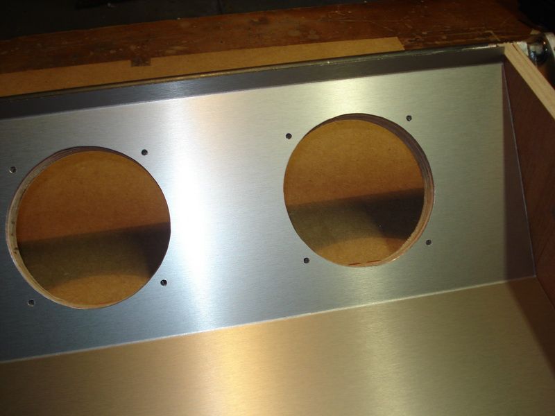
Mounted the speakers for the first time.
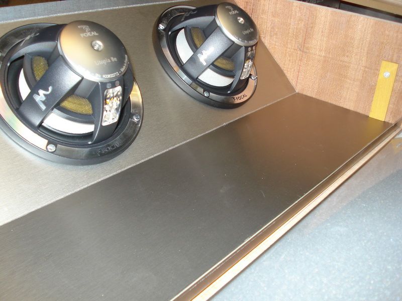
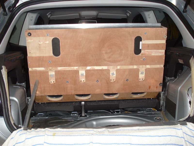
4 in a row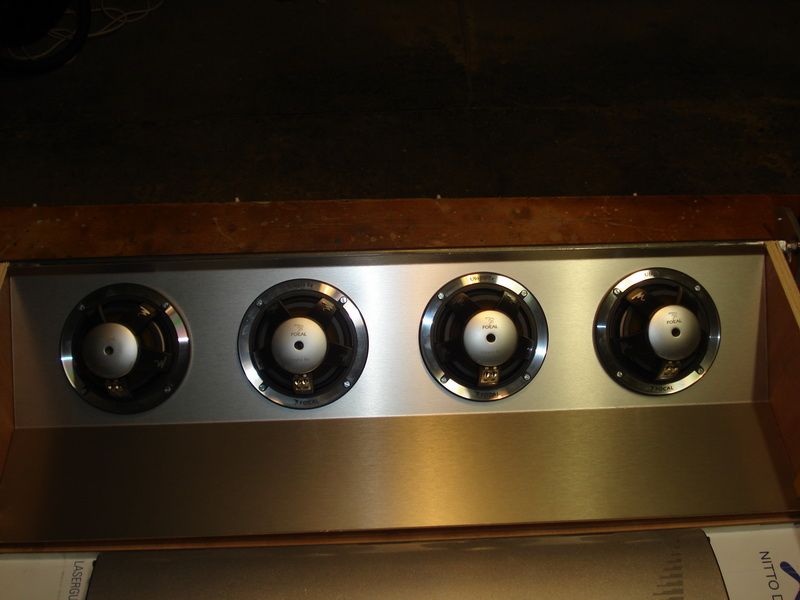
Posted By: robolop
Date Posted: December 22, 2012 at 7:18 PM
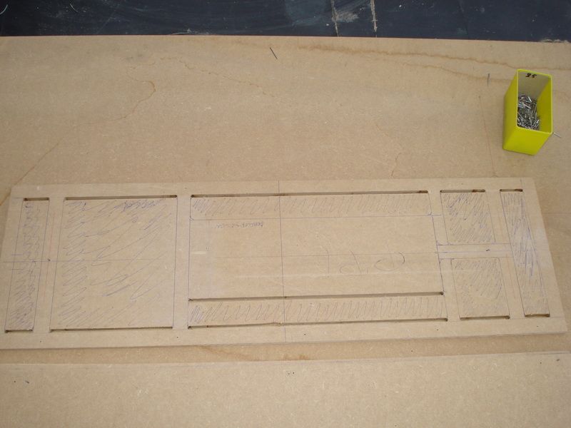
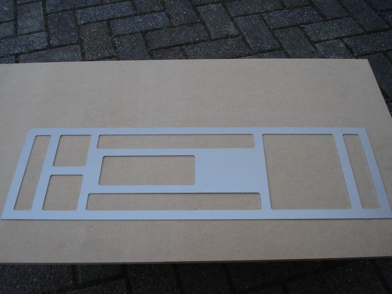
Because Im going to mount the equalizer onto the amplifier, I decided to make an aluminum plate.
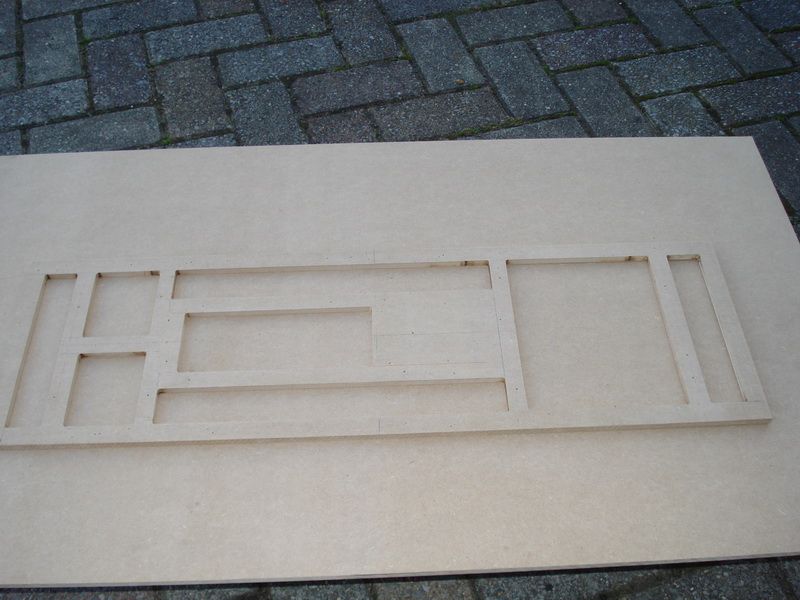
First of all I drew out everything on a piece of MDF, 8mm thick.
The MDF will serve as a mold for the actually alu plate.
Here you can see how I started.
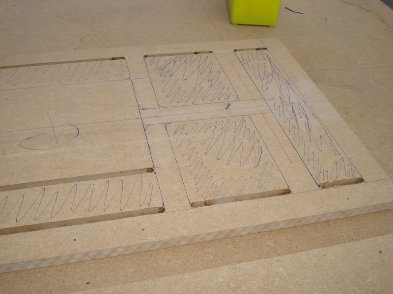
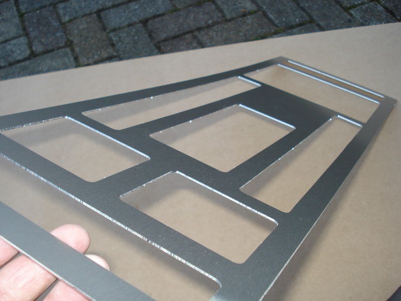
The piece is finished, and Im happy with the result.
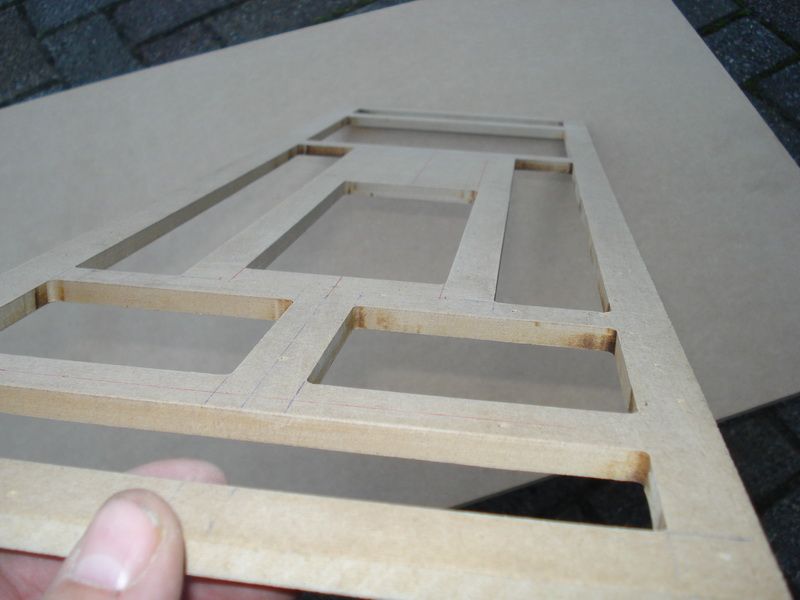
I sawed out the alu plate with the jigsaw, after that I taped it on the MDF.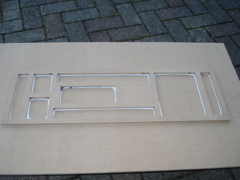
Then I started to mill this with the copymill.
The result:
I just need to sand the edges
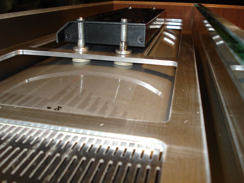
Then I mounted the EQ on there with 4 screws, and layed it on the amplifier.
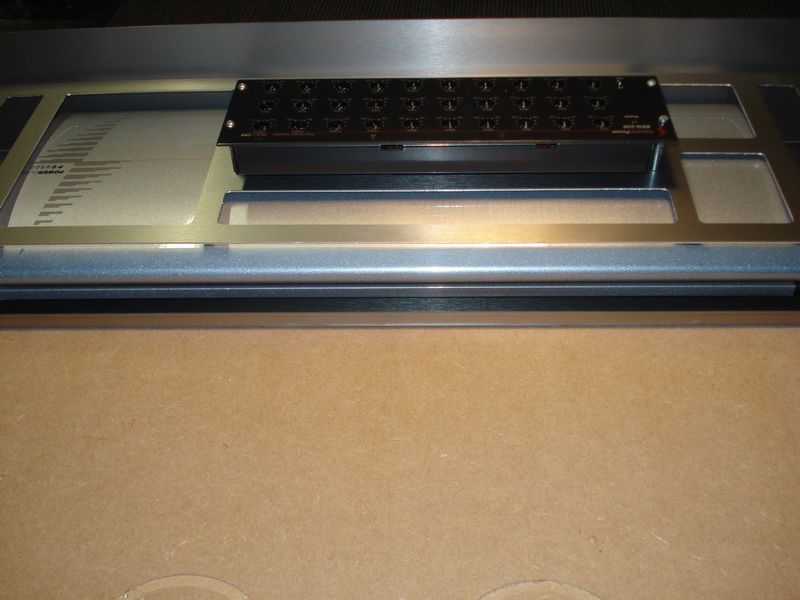
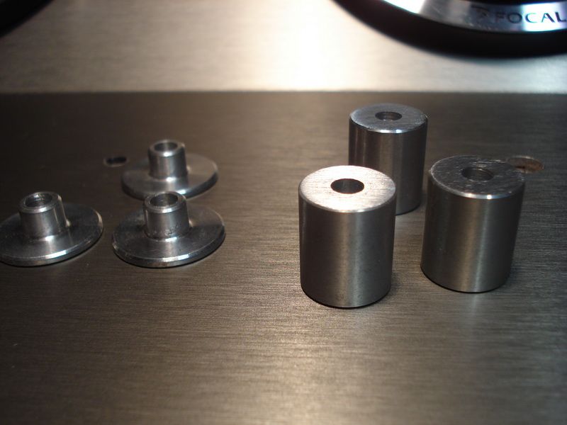
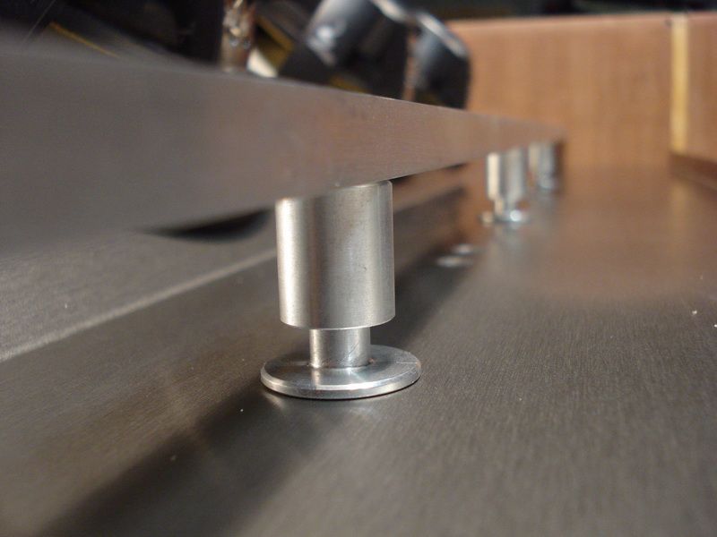
The busses wont stay as in this setup. Im going to let some made on the height I want.
Here you can see the amp also stand on busses. I did this to work away the cables.
For the first time, I timed how long I worked on this Aluminum plate.
Drawing on MDF
Mill the MDF
Saw the Alu
Mill out the alu
This all took me about 5 hours
But as you guys already know, I dont give a f*k how long it took me, as long as the result is OK for me
Posted By: robolop
Date Posted: December 22, 2012 at 7:21 PM
Here you see what Ive done to work away the cables in an easy and fast way.
Close to the bottom of the amp, I made 2 oval holes (L and R)
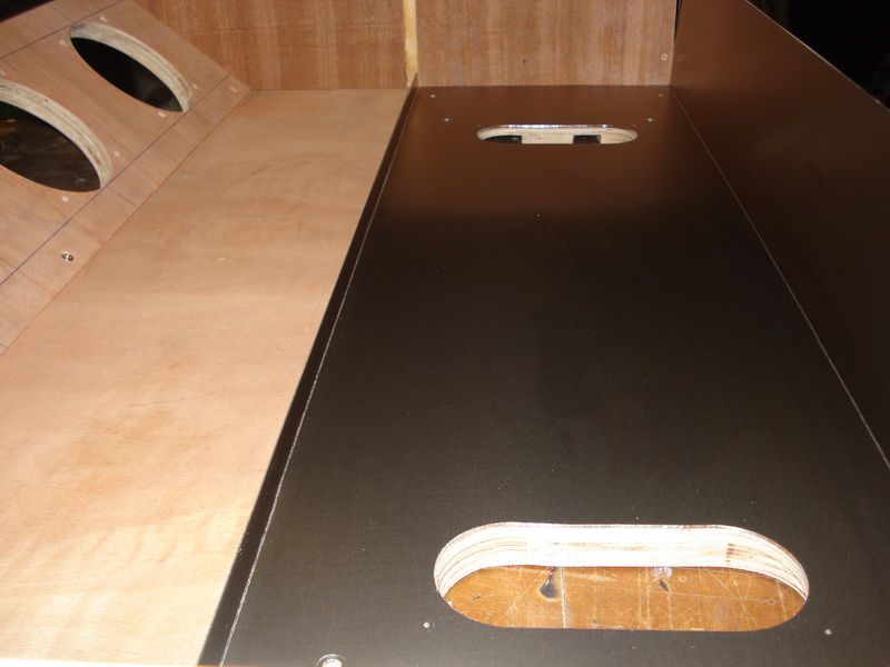
On the bottom side I milled out a big sloth to place the cables in.
Once I placed the cables there, Im going to screw a thin plate on there so the bottom side will look descent too.
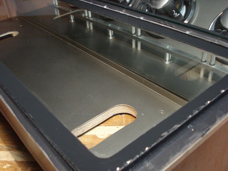
I chose glass to work out the separation between the sub-box and the amplifier.
The glass is hardened, 12mm thick.
I chose this solution, so it will maybe look bigger, cause its all in one space.
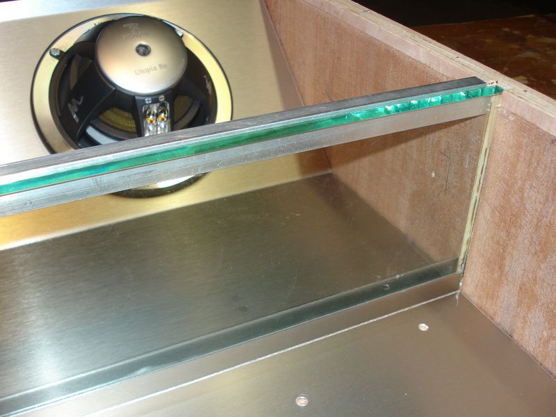
I milled out a ditch on the left and the right.
Then I let someone bend me a lip on the alu of the amp and subbox.
The glass rests between them. Offcourse Im going to kit it all off when the subbox is closed.
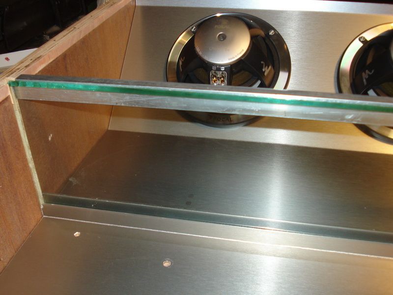
Off course I need to have some material left and right to screw the box tight.
This Ill solve by glueing an aluminium bar against the glass.
Here you can see that this bar is also tightened left and right.
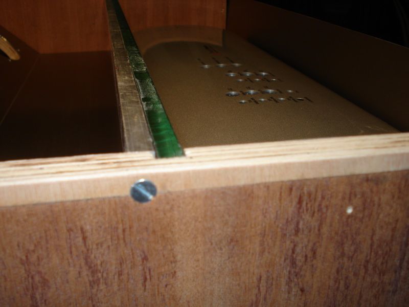
In that alu I can tap screwthread to screw my cover on. On the side Ill place long woodbolts and on the back (hinge) I need to straighten it out with polyester, then its possible I also tap in some screwthread.
Posted By: robolop
Date Posted: December 22, 2012 at 7:21 PM
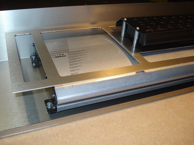
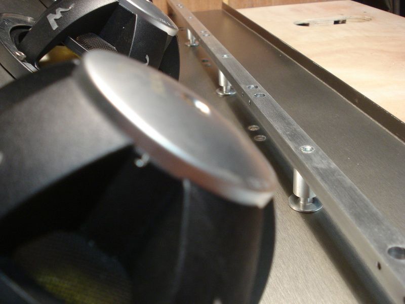
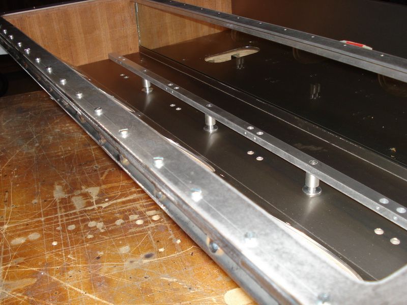
I changed the plate which is on the amplifier. I widened it a bit more.
I also added a second plate underneath it. Ive done this to give it a more tough look.
The sides of the thick plate will get polished, and the thin plate will be sprayed in black.
On the sides I foresaw other plates with fine openings.
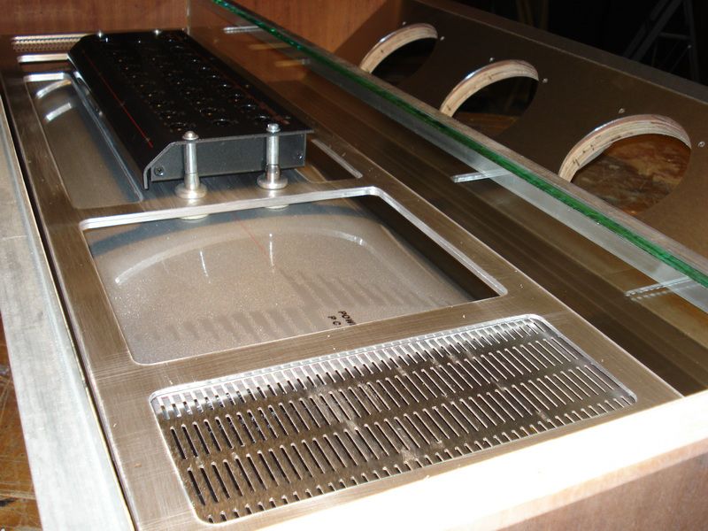
About those openings, this will provide some more cooling for the amp, and off course look even better.
You can also see that the plate is placed on 4 rubbers, ON the amp.
On the outside I will add 4 alu busses, but need to let them make first.
Posted By: robolop
Date Posted: December 22, 2012 at 7:22 PM
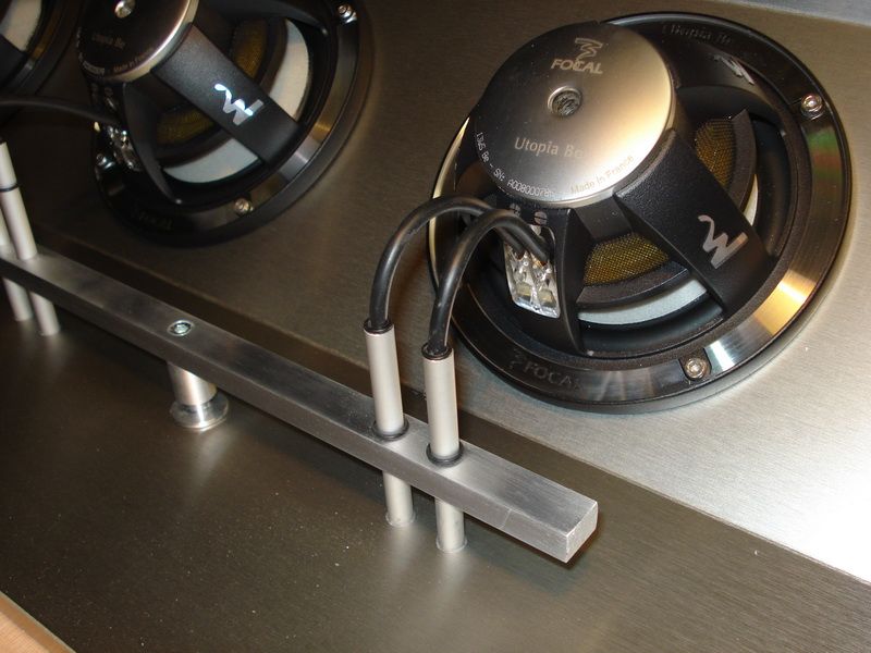
This time I wont be working with copper for the connection of the Focal Subs. When I started this project, I said I was going to keep it basic .and Im getting the feeling its getting a bit out of hand again .
I want to show with this connection , that you can make beautiful and good things with simple stuff.
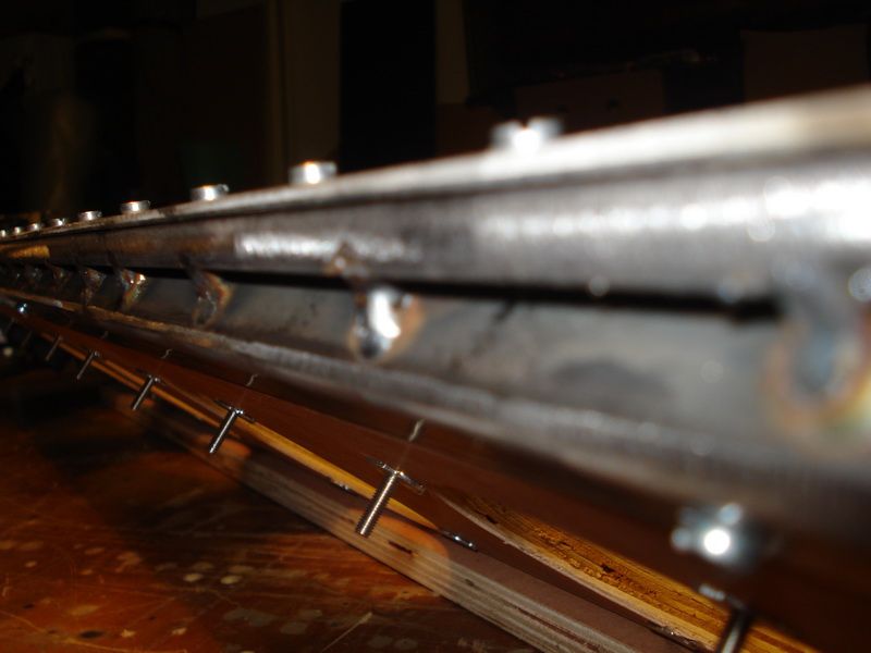
First I let a friend make me a couple of aluminium busses.
Then I took an aluminium rectangular bar from 10mm on 15mm.
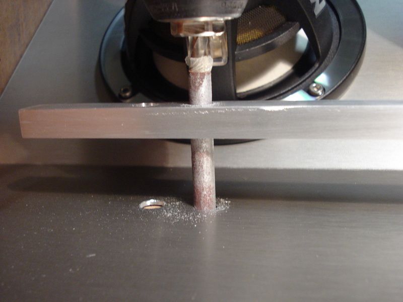
Once I perfectly measured where the holes need to be, I drilled all holes with a pillar drill machine.
This was for me the best way to drill the holes STRAIGHT.
Then I taped a lath in the subbox, and drilled the holes into the wood.
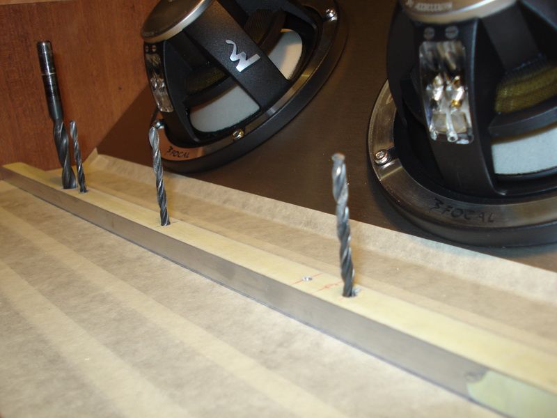
You can see, that I when I drilled a hole, I let the drill stay into the hole. That way the lath cant go anywhere, and it all stays on 1 line.
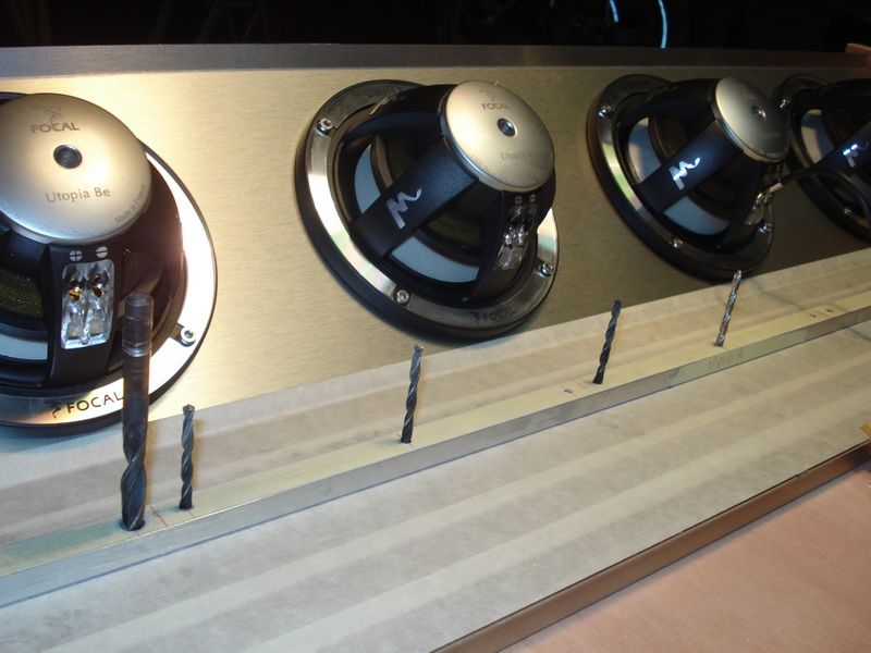
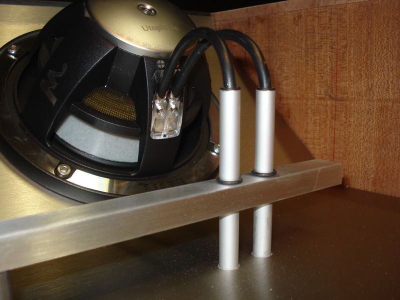
Here you can see the alu bar, with the busses underneath.
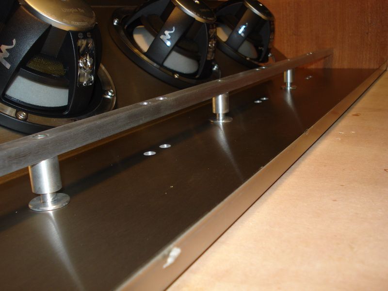
The bar is mounted on 3 places with normal inbus-screws, which are sunken in. These inbus-screws you will see everywhere in this install.
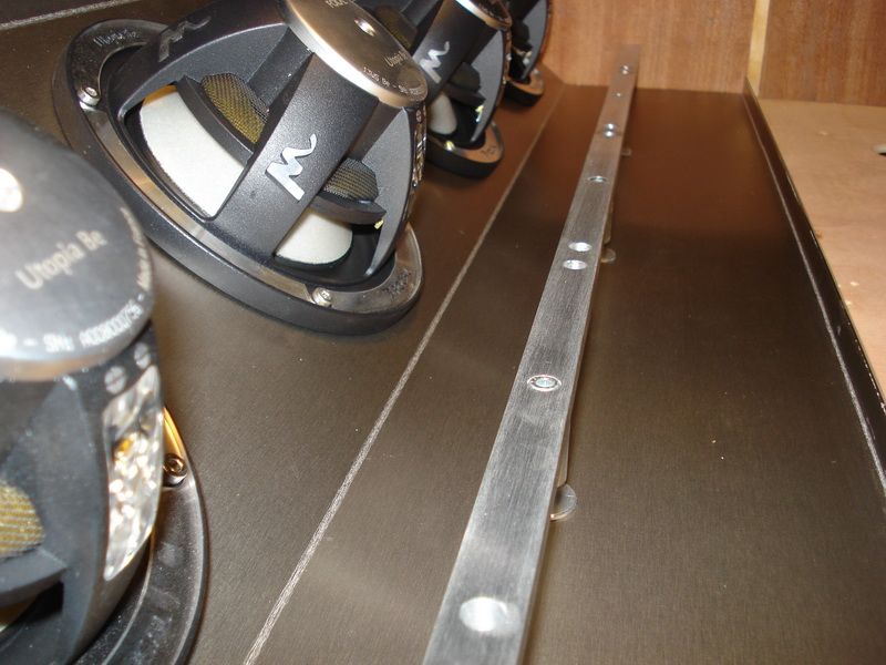
Where the connection of the speaker will come, you can see holes of 8mm. Here will a little anodized aluminium tube will be placed, where the cable will run through.
When you look closely onto the picture, you can see I made big holes on the backside, and provided them with screwthread. Here will come an adjusting screw of M4 onto the little alu tube, so itll keep its place. And be doing this Im sure that it wont go vibrating cause of the subbox pressure.
I need to order the alu busses cause they arent in stock.
Theyll be delivered next week.
I also hope that the temperature will go up a bit, cause where Im working now, theres no heating. And for those little works, its freeeeeeezing on my hands (and the rest)

Posted By: robolop
Date Posted: December 22, 2012 at 7:23 PM
I grabbed the mill from out the cupboard and started making some sloths on the bottomside (for the cables from the subs)
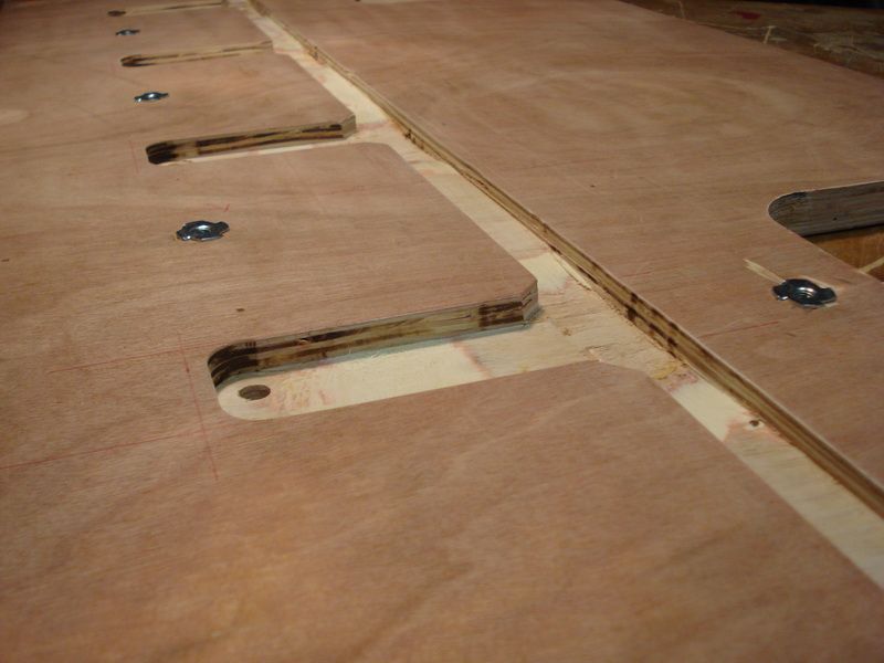
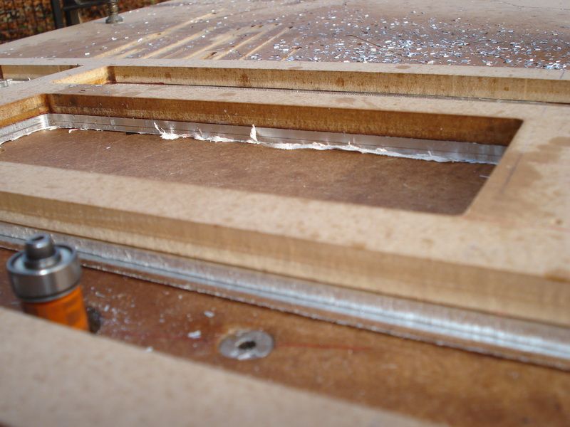
Then I started making frames where the glass will rest on. This alu plate is about 3mm thick.
Then I sanded it down, and drew it out.
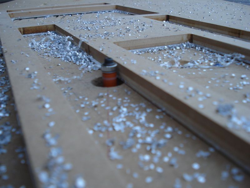
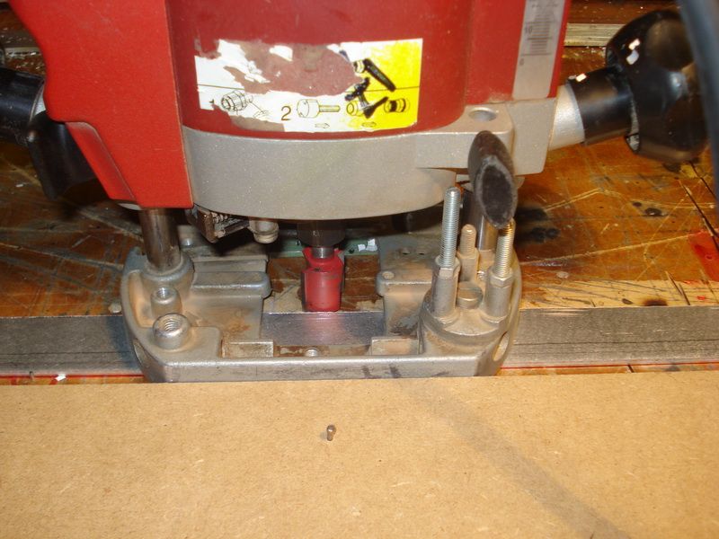
Then I cut away as much as possible with the jigsaw. Because its impossible to saw straight with a jigsaw, I milled the last mm.
Pretty easy to do.
Its superimportant that the aluminium is taped to the table. I did it with dubbel sided tape.
You can also see that the plate is laying against some nails. I knock them qual to the top of the plate, so the mill doesnt flip when I go over them.
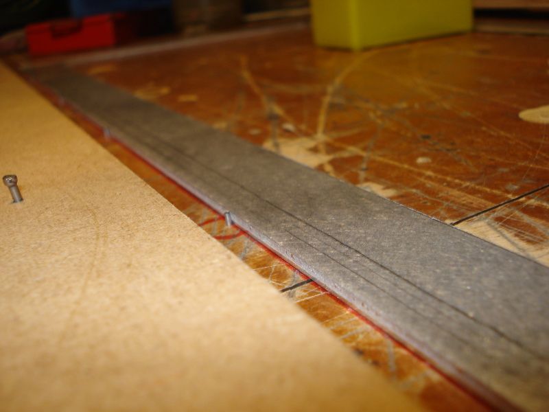
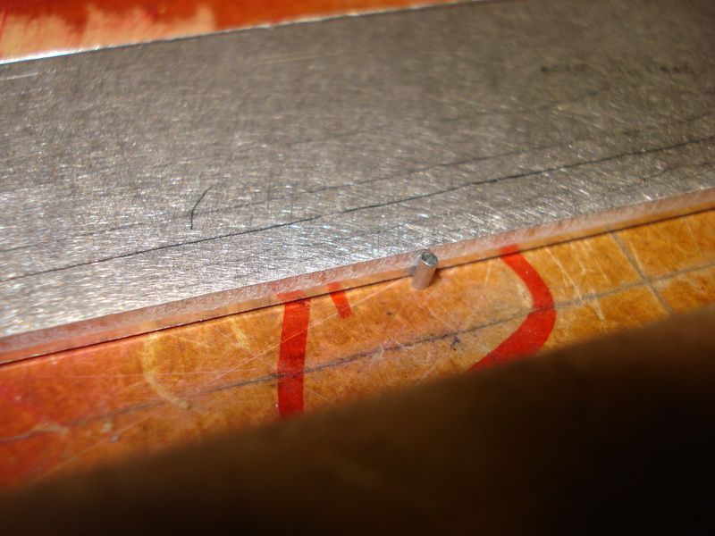
And a lath which functions as a glider for the mill.
This looks pretty smooth and easy, but when you look at the clock, hours pass by. But I dont care about the time.

Posted By: robolop
Date Posted: December 22, 2012 at 7:23 PM
Cause of the cold this week, I didnt manage to do much. Where Im working at the moment, theres no heating, and you can feel the cold comin out of the ground. There are nicer days to work on an install.
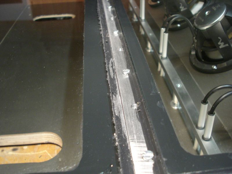
The 2 alu frames (for the glas to rest on) are finished. On the back of the subbox, where the hinge is placed, I had to weld an extra iron.
After that I drilled a LOOOOOOOOOOOOOOT of holes in the aluminium, and also in the iron and alu bar. After that I made some screw-thread in there so I could tighten it all nicely. Remember, the subbox needs to be 100% closed.
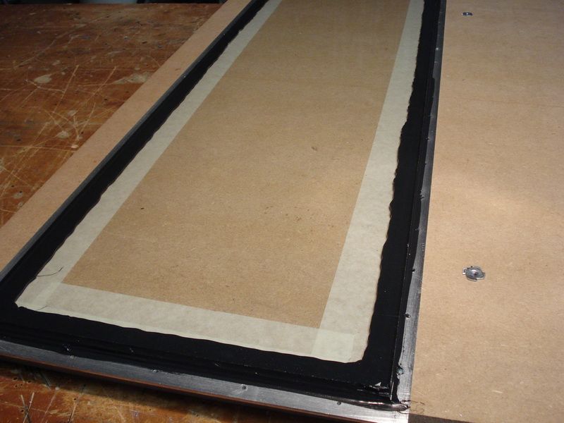
Once the holes were good, I taped the glass onto the aluminium.
I chose 2x4mm laminated glass. This is the same as the glass thats in your front windshield of your car. I chose this because its superstrong, be also, must it ever break, the shattered pieces wont fall apart, due to the special film thats in between.
You never know the glass will burst after my wife plants a bag of potatoes into the trunk, then it wont be the end of the world
just needs a new glass.
I glued the glass with black TEK7.
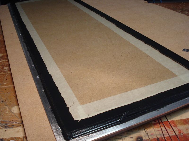
I left this to dry for more than four days, and it still wasnt dry. Probably because its cold and moist in my garage for the moment.
Then I worked on the connections of the woofers.
Here you can see the 8 alu tubes where the cable gets through. You can also see LED holders, and little O-rings.
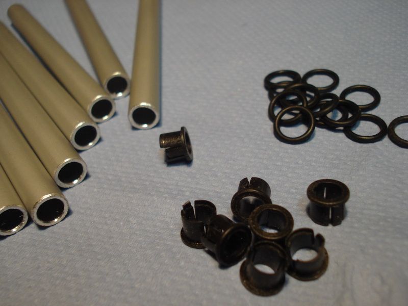
First of all, I glued the led holders into the alu tubes with 2 components-glue
Because my cable didnt got through anymore, I had to abrade the LED holders one by one till the cables got through again.
F*CKN JOB...
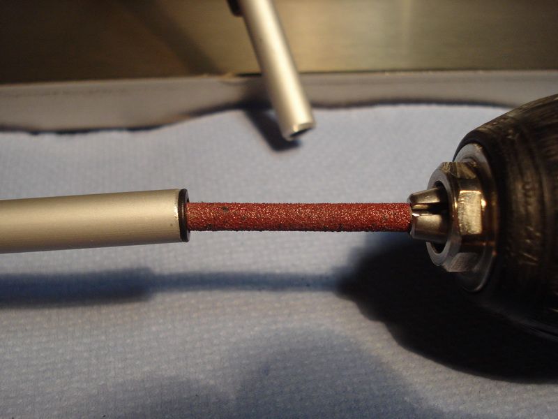
Another doodiety job was that I had to sand down the inside of the holes, where the tubes glide through.
Once all this was done, I could place the tubes through the holes without scratching it.
You can also see the O-rings I slipped over it, to get a nice finishing touch.
With these connections I want to prove that it doesnt always have to be copper, and you can make nice things with normal stuff.
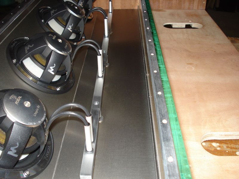
Here you see how the glass rests on the subbox, and how its screwed. Offcourse Im going to place rubber in between to get a more perfect seal.
The glass on the amplifier part: This will be tightened with a couple of screws, so if I have to turn the EQ, its just a matter of screwing some screws loose.
Another cool shot
Posted By: robolop
Date Posted: December 22, 2012 at 7:24 PM
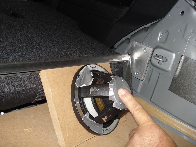
Exiting day today.
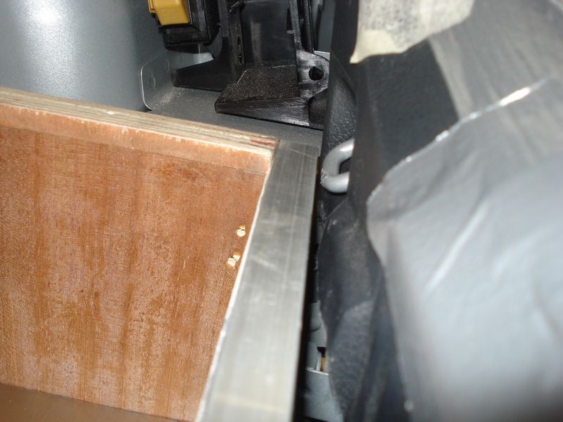
I mounted the box into the trunk. I used every inch possible in there, but I had a good feeling when I let the thing go up and down.
I had to do a minor adjustment with the hammer. The box didnt go (only for a couple of mm) by the eyes on the back of the trunk
STOP- Hammertime! lol
You can see how close it all is.
I also changed something on the hinge and now I need to finish it off.
When the trunk is up to gain access to the spare wheel, I need to flatten out the back seat
I think the spare wheel is easy accessible, no?
Posted By: robolop
Date Posted: February 17, 2013 at 10:50 AM
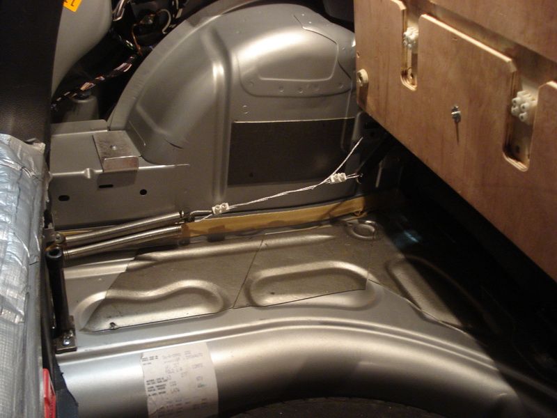
I managed to lift the box in the trunk, without using much force.
It lifts easy with only using a couple of fingers.
You can see how easy I managed to solve this.
I welded 2 springs together. I had to do this cause 1 long one, wasn't strong enough.
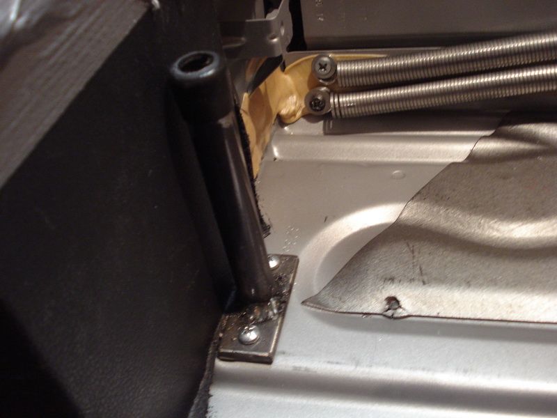
I also used a steel cable of 3mm.
To tighten these, I used some ordinary luster-clamps.
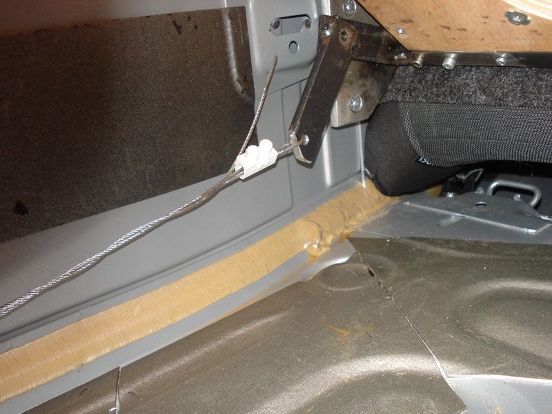
You can also see I mounted the springs on top of each other, otherwise there was no room.
You can see on the length of the cable, I can still add more tension on it.
That I will do once it's all mounted, then I can do the fine tuning of it.
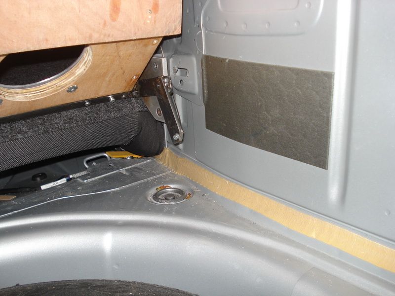
Here you can see how tight it all is next to the box, and what I mean with putting the springs on each other.


The springs and the hinge, there's also some fine-tuning necessary. I have to sanded down, and spray it.
Around the springs I'm going to pull a tyre of a kidsbicycle, so that it can't vibrate.
The box is placed on 4 rubbers, also for the vibration. But I also had to make something to tighten the box on once it's closed.
I had to do this in a simple way, so that my wife didn't need to go throught a procedure of 10 things before getting to the spare wheel.
I've managed to solve this with only 1 inbus-screw
The shackle I made, is screwed in the trunk. You can also see a rubber cap on it.
Underneath I tapped some screwthread.

Then I made a little aluminium plate, and screwed it to the box.

So when the box is closed, the plate comes directly on the shackle.

I tuned this with another inbus-screw (M10).

And so you can screw it loose or tight with only 1 screw.

Sometimes I wonder what the hell I'm doing with the bimmer.
When I was working on this thing, I ask myself why I'm not doing things more simple. No head-aches, and in a much faster pace.

Posted By: 9074life
Date Posted: October 23, 2021 at 6:23 AM
-------------
Alaskanbrewed