Difficulty in Motorcycle Alarm Wiring
Printed From: the12volt.com
Forum Name: Motorcycle Electronics
Forum Discription: Installing Stereos, Alarms, Remote Starters, Lights, Garage Door Openers and other electronics on motorcycles.
URL: https://www.the12volt.com/installbay/forum_posts.asp?tid=102427
Printed Date: May 04, 2026 at 4:11 PM
Topic: Difficulty in Motorcycle Alarm Wiring
Posted By: cortina
Subject: Difficulty in Motorcycle Alarm Wiring
Date Posted: February 22, 2008 at 4:11 AM
Hello All :) I have this difficulty in interpreting this motorcycle wiring diagram which came with the alarm: 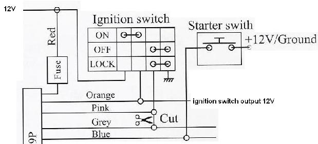 This is how i think this should be done but i definetely have a fault since the pink wire goes to ground when the ignition is switched on when alarm is in arm, hence shorting the ignition 12v to ground. 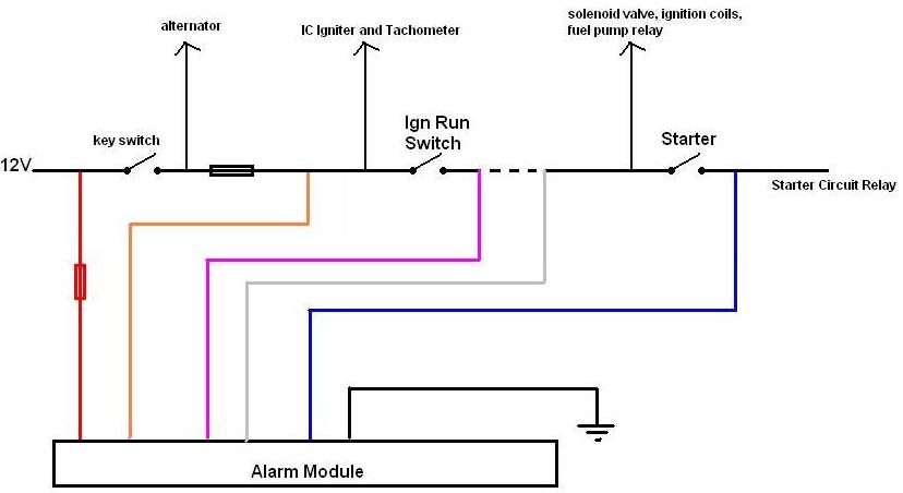 Thanks for your help.
Replies:
Posted By: dualsport
Date Posted: February 24, 2008 at 10:15 AM
Sounds like the pink wire is supposed to disable the ignition when the alarm is armed the same way as if the ignition is turned off and locked; if you just want to avoid blowing the fuse when you forget to disarm before switching on the ignition, maybe add a relay to open up the line from the ign run switch, with the coil controlled by the pink line (gnd switched) and powered from the output side of the ign run switch. The NC and COM relay contacts would be used inline with the switch, opening the connection when you turn on the ignition while the alarm is still armed.
Posted By: dualsport
Date Posted: February 24, 2008 at 10:31 AM
Do the pink and grey wires from the alarm look like isolated contacts that are for simulating the contact closures when ign is off and locked?
Probably they're meant for an ignition kill switch independent of the 12V ign power; when the line shorted, the ignition is disabled, without turning off the ign power.
If your bike doesn't use that kind of setup but instead opens up power to shut down the ignition then adding a relay would convert it to the open-when-armed instead of shorted-when-armed.
Posted By: cortina
Date Posted: February 24, 2008 at 2:20 PM
I have wired as in the above.
Result: All arming / disarming features work well, starter rotates when remote starting is done, but there is no spark at sparking plugs.
Yes dualsport i had a few fuses blown after before realising what was causing problem, as well said by yourself.
Then i just eliminated the pink and grey wires, and left ignition switch on, hence 12V from ACC on all components powered by ignition switch. However with the same result (starter rotates but no spark). This is actually very confusing since there is supply on ignition coils :s
Another query from the wiring above, if the bike starts with remote startup, how is the alarm "brain" triggered so that starter does not continue starting for 3 times (approx. 2 seconds each) ?
Thanks for your replies :)
Posted By: dualsport
Date Posted: February 24, 2008 at 11:03 PM
Did you check that everything is powered up when the alarm is autostarted? If you turn the ignition on before autostarting, does it start up then?
The orange wire from the alarm should be supplying the 12V to the same points as the key switch; make sure it's doing that-
Since there's no tach connection, it may be relying on the voltage rising when it starts up and the battery is charging to tell when it's started. If it doesn't see it go up, it'll assume it didn't start and repeat the start cycle.
Posted By: cortina
Date Posted: February 25, 2008 at 5:53 AM
Thanks dualsport for your helpful replies ;)
I will carefully review the motorcycle wiring diagram, to check if all components are being powered up.
Posted By: cortina
Date Posted: February 25, 2008 at 6:29 AM
so basically this is the ignition switch diagram of the bike

I have connected the orange wire to the brown wire (which then goes to fuse box - ACC).
The grey wire of the ignition switch also goes to the IC Igniter of the bike. Hence could be causing the no-spark-problem. Will check this soon.
Posted By: dualsport
Date Posted: February 25, 2008 at 7:58 AM
That sounds like the problem. If your alarm doesn't have provisions for a second ignition output, you can use a relay running off the orange wire to supply the second ignition power output. If the only reason they separated the two ignition lines is for current handling of the keyswitch you might be able to connect them together, but it'd be safer to isolate the two the same way as the original configuration, in case there was some purpose for it.
Posted By: cortina
Date Posted: February 26, 2008 at 6:39 AM
i have checked the grey wire with the voltmeter and when the IC igniter is connected, there is only 6V hence must be reason why it was not connected to the ACC 12V! however when the connector is removed there is 12V at the grey wire. I guess i must use a normally open relay combination and switch to 12V when alarm acc trigger is on. Please confirm.
Posted By: dualsport
Date Posted: February 26, 2008 at 8:38 AM
Are you referring to the grey wire from the OEM bike harness or the one from your alarm? On the OEM harness, when you switch the ignition on using the key, it should show 12V on it.
When you're autostarting it, something has to supply power to it, and normally it would be the orange wire from your alarm. You could try connecting the brown and grey wires on the OEM harness and do without the extra relay, or add a relay to supply the second ignition output.
You'd just use the orange alarm output wire to switch the relay.
Posted By: cortina
Date Posted: February 26, 2008 at 12:05 PM
the grey OEM harness wire i m refering to. Coz its working on 6V :S however when the connecor is removed there is 12V.... i ll just use a relay and switch it through the orange wire.
Thanks dualsport, seems like ur the only alarms guru in here ;)
|