12 to 24v automatic swap
Printed From: the12volt.com
Forum Name: Motorcycle Electronics
Forum Discription: Installing Stereos, Alarms, Remote Starters, Lights, Garage Door Openers and other electronics on motorcycles.
URL: https://www.the12volt.com/installbay/forum_posts.asp?tid=120086
Printed Date: April 29, 2026 at 5:25 PM
Topic: 12 to 24v automatic swap
Posted By: gap4652
Subject: 12 to 24v automatic swap
Date Posted: February 12, 2010 at 1:42 PM
I have a guy who is bringing me a 08 motorcycle and wants to make it crank on a 24v system when the starter button is pushed and then it swap back to 12v when it is released but charge both batteries this can be done through a system of 2 relays. Does anyone know a diagram for this application or make a diagram to help me with it. I have seen them for sale through some motorcycle aftermarket parts places but no diagrams. Thanks
Replies:
Posted By: oldspark
Date Posted: February 12, 2010 at 2:50 PM
I'm reluctant to find or draw a pic without knowing the reason(ing) behind this.
But there are vehicles that do similar - ie, 12V diesel cars with 24V starters or glow-plus - maybe you can find those...
Hopefully others have some handy link or pic.
And further to the above, I won't ask if the batteries will be paralleled when not being charged or used for starting.... (The owner can no doubt afford new batteries.)
Posted By: Ween
Date Posted: February 12, 2010 at 2:57 PM
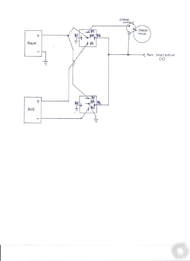
hi, you'll need two spdt 12 volt coil contactors with the contacts rated to carry the starter current when operating on 24 volts. the contactors would be wired as follows: contactor 1: common terminal to aux battery (+), normally closed terminal to stock battery (+), normally open terminal to starter solenoid (remove existing wiring from this terminal). contactor 2: common terminal to aux battery (-), normally closed terminal to vehicle chassis, normally open terminal to stock battery (+). wire the coils of both contactors in parallel, connect to coil terminal(s) of existing starter solenoid. you may want to have a relay operating the the contactor's coils, depending upon how the existing starter solenoid is switched. is this for a race bike application?..lots of compression? m
Posted By: gap4652
Date Posted: February 12, 2010 at 3:16 PM
24v is only used to crank the motorcycle then it switches back to 12v It should series the batteries in starting mode then back to parallel in run mode.This is commonly used on big bore cycles to help crank them but the secondary battery is usually charged by a battery charger plugged in. tigerracingproducts.com has a setup for this application but it is expensive. and can be made cheaper than bought.
Posted By: oldspark
Date Posted: February 12, 2010 at 4:33 PM
Hi Gap,
Sorry for my standoffishness etc, but thanks for the reply and description.
Nice to know there are legit reasons... Not that I'm up with "recent" developments since my '84 GPz900 & even older Ducati lol, but I should know better than to doubt people here. (Alas a recent local meeting threw me back into the world of short-on-memories and long-on-morons.)
Not sure now that a pic is needed...(?) (Thanks Ween!)
As to those commercial offerings, I thought the prices seemed reasonable - until I saw their cheaper version.... a DPDT switch with cabling.
IMO way too expensive compared to the auto-relay solution. (Not that assembly and the 30A(??) rated switch is cheap - nor would its extra heavy cable help - but for $160 vs $100, give me the auto relay!)
But yeah - just 2 relays as Ween described.
Though I would have thought the relays turned on by the starter button - but that depends on what the " existing starter solenoid" is, but I thinks that's ok. (If it's a 12V relay, cool. If it's the solenoid as integral in a car etc starter, then that will (need to be) 24V etc. But bike starters are probably NOT the latter solenoid-throwout types.)
As to paralleling of batteries - that's fine during use and charging.
It's when batteries are left idling paralleled - idling meaning no load nor charge. Over time, one will pull the other down - maybe to a lower equalised level, but eventually premature failure (of the 2nd battery).
In simple terms(??!), for matched batteries, the failure rate of the 2 combined batteries is doubled. (Not the same has half the reliability, but it is twice as unreliable.)
For unmatched batteries - whether different sizes, types or matched batteries if different temperature of different circuit paths - failure is even quicker.
That's where the reliable paralleling method is to only parallel whilst charging (to keep batteries independent for later 12V cranking), or in this situation, whilst the ignition is on.
That's a 3-relay configuration though....
(Hmmm - a potential drawing looming? Like I did (bother to) visit that Feline site...)
And I retract my earlier smart-Rs comment about the owner affording new batteries. 
Posted By: gap4652
Date Posted: February 13, 2010 at 3:25 AM
I understand where you are coming from. I also think it is a relay type switch it initiates when the starter button is pressed. I am still gonna have to have some kind of schematic as Weens post has me somewhat confused any help is greatly appreciated. Thanks
Posted By: gap4652
Date Posted: February 15, 2010 at 4:38 PM
Can anyone show me a diagram for this. Thanks
Posted By: Ween
Date Posted: February 15, 2010 at 8:37 PM
Posted By: oldspark
Date Posted: February 16, 2010 at 3:26 AM
And as a schematic to Ween's wiring diagram, the following with some notes...
However, ignoring the diagrams notes, my (APPA) and Ween's diagrams should be equivalent - though mine/APPA doesn't detail/show the stater solenoid...
With thanks to APPA (yes, permission granted for use on the12volt.com only in this thread only but may be cross-referenced or linked to this thread).
It shows the two battery's being normally connected in parallel.
They are connected in series to provide 24V only when the 12V "start signal" is applied - as shown this is with IGN on and the START button pressed.
In practice, the start signal +12V could be from the starter motor's relay (if used) or its solenoid (depending on its topology).
Note that although only one coil/solenoid is shown as if a DPDT relay is used, for two SPDT relays, replace that coil with TWO parallel coils (ie - just draw another beside it between the same START wire & GND).
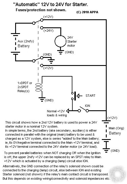
The drawing notes mention extra enhancements but do not provide the detail directly.... (But look at Ween's wiring, and assuming the starter solenoid is....)
The enhancements reflect that parallel connection of batteries is NOT desirable UNLESS charging or in use for extended reserve time. (Parallel idle (unused) batteries leads to premature failure of the batteries.)
The notes hence suggest an alternative "normal" connection of 24V mode (ie, with ignition off or when starting) and that the DPDT relay is energised only when charging OR when the ignition is on - therefore isolating the batteries when not in use.
Alternatively, another relay can be inserted into the proposed circuit that only connects the +12V of each battery when charging or ignition on.
The former requires that the DPDT relay is ON when the vehicle/bike is in use whereas for the latter, the DPDT relay is only ON when starting - but that requires and exra relay which is ON when (the bike is) in use - ie, either IGN is ON or the alternator is charging (depending on what is desired).
Remember though - this is only to keep the batteries isolated (NOT paralleled) when the vehicle of off, for longer and independent battery life.
Simple, isn't it?
|