charging two 12v batteries in series
Printed From: the12volt.comForum Name: Motorcycle Electronics
Forum Discription: Installing Stereos, Alarms, Remote Starters, Lights, Garage Door Openers and other electronics on motorcycles.
URL: https://www.the12volt.com/installbay/forum_posts.asp?tid=128392
Printed Date: May 12, 2026 at 12:33 PM
Topic: charging two 12v batteries in series
Posted By: tuvee
Subject: charging two 12v batteries in series
Date Posted: August 29, 2011 at 6:13 PM
Hello all. My first post on your site so be gentle..
Google led me here while searching for help with my setup and I'm hoping you guys can point me in the right direction.
This is the thread I was reading (hope I'm doing this right) https://www.the12volt.com/installbay/forum_posts.asp?tid=120086&KW=24v+starter although I have a slightly different requirement.
My bike has a boRED / stroked, high compression engine and has an additional battery wired in series to provide 24v to the starter motor.
This second battery is wired between the starter relay and the starter motor and it works very well. I copied this simple setup from a number of LSR bikes and the motor seems to hold up very well.
The downside is that the second battery isn't charged by the bike. This is ok for a competition motor but I use mine on the roads so need to find a way of charging both on the bike.
I've chatted with a couple of auto electricians and both seem reluctant to take on the job and I'm not sure why.
I had thought to wire the current configuration through the normally open contacts on a relay (triggered by the start switch) and a path to ground through the normally closed side then hook both battery positives to a 'split charge' relay and back to the generator (I've a basic drawing of the plan if I've not explained myself very well).
Do you guys think this would work or can you suggest an alternative?
Much appreciate any help you can give.
Tuvee
-------------
Artificial intelligence is no match for natural stupidity
Replies:
Posted By: tuvee
Date Posted: August 29, 2011 at 6:15 PM
Sorry guys, forgot to add the bike details:
2005 Suzuki Hayabusa, 1445cc.
-------------
Artificial intelligence is no match for natural stupidity
2005 Suzuki Hayabusa, 1445cc.
-------------
Artificial intelligence is no match for natural stupidity
Posted By: oldspark
Date Posted: August 30, 2011 at 12:12 AM
LOL! I was going to say that this is the same issue as 24v supply from multiple 12v cells.
But now I see that your link to 12 to 24v automatic swap has the info/diagram I was looking for in that thread!
{ Hey - attempted humor follows. Bear with me if that isn't obvious! }
As to your "My first post on your site so be gentle... " - how do you expect me to be? Here you are, your first post in this forum, and you show up and old timer like me! The cheek of it all!
How dare you find something that I couldn't find. And something I posted!
AND it reeks of the same freaky timing coincidence that a certain un-named person (Howie II) has!
LOL! Thanks for that link. You have just knocked off one of my "to do" things... (I'll now sleep easier at night!)
[ Bluddy newbs. I suppose your are young to! Damned youngies - so talented that the mainstream establishment has to knock them - not that I ever get socially political in MY replies. Never! (LOLs again.) ]
I don't see any issue... I wonder what their reluctancy is?
Maybe that it could "over stress" the charger (alternator), but that should not happen. (In fact, IMO, it is quite the opposite! I can explain, or link elsewhere [but you'd probably find THAT before me too ha ha!].)
BUT - I need to re-check the sanity of that old fart's drawing (he's can be a complete idiot you know, at least if some of the parts weren't missing. [I plagiarised that from chanen1953... OMG - it's from the same thread that I first mentioned above. Don't tell me that is mere coincidence too!!! Freaky indeed!]...)
Besides, are you able or willing to do this, or will you be using recalcitrants ... I mean, reluctatrants? (Maybe a "special submission" for them - especially after that last slip. If only I could edit that slip out, but it's too late after someone else has replied....)
For convenience and as a reference, herewith that stupid Old Fart's "lost" diagram. But I'll check that for suitability or possible simplification later...
BTW tuvee - welcome to the12volt. Others will not ramble as I do (they are Professional!) so I'll urge you to give the12volt as second chance.
But I am already grateful to you.
Thanks!
Posted By: tuvee
Date Posted: August 30, 2011 at 3:45 AM
Thanks for the info and welcome oldspark but you give me too much credit - google and you guys did the clever work.
I suspect that the shops I've been to are more interested in a fast turn around of fairly standard jobs and don't have the time (or inclination) to figure out a one off puzzle. Personally, I love a challenge but don't have the level of expertise to be certain that what I'm doing is 100% correct (or even good working practise).
As a rookie I can't post images but I plan to use a suitably heavy duty relay to disconnect both terminals of the starter battery from its 'charge' configuration and wire it into the 'start' position when the start button is pressed. I think the starter draws in the region of 80A on a stock 12v system so will need a relay with plenty headroom. What should I be looking at as far as additional fusing is concerned?
Getting the starter to work is easy enough but it's re-charging the additional battery that's the problem since there's no common earth in the start configuration. The magic of diodes and isolators etc is way above my head - I'm a mechanical guy and my thinking runs to 'lift the terminals off there and put them on that bit' - electrically :-)
Btw, I'm prone to a bit of verbal excess myself so go for it. Glad I've found this site cos there's a few interesting projects on here to be dabbled with once I get this sorted.
-------------
Artificial intelligence is no match for natural stupidity
Posted By: oldspark
Date Posted: August 30, 2011 at 5:20 AM
Ah yes - Google. That's what made me a Systems Admin for a somewhat big and nationally important management system...
But tuvee, I also have organisational Management skills, and let me tell you, I am NOT interested in excuses - I am only interested in OUTCOMES! Your feeble excuse does negate the superb outcome!
Besides, alleged wit aside, I like your last reply. Fast turnaround. Your caution and reservations. Relay headroom. It's Rookies like you that should be complimented! (Ok, c'mon - who's setting me up? Ah ha - it must be the UK!)
Ok, an 80A starter. Let's assume a 100A relay for headroom.
Maybe as a starting point (ha ha, starting... get it? Sorry!) a relay like the FRC6BC-1 SPDT 150A N.O. 100A N.C. for AUD$14.95 from Jaycar, Cat no. SY4073 - Automotive Relay 150A SPDT . You should/might find better locally, but IMO that's a good relay; robust and (reasonably?) weatherproof with 6.4mm (1/4") spades for the coil and 9mm spades for the contacts.
Its only problem - no mounting lugs. (I've been meaning to search for equivalents with good mounting options.)
FYI - as usual with xxDT relays, the NC (normally closed) contacts have a lower rating than NO (normally open) because they only have spring-force/pressure to keep the contacts closed.
The NO contacts which close when the relay/coil is energised have the (usually) stronger magnetic force that keeps them closed.
(Rem: "Normally" means "as stored on a shelf" - ie, no power. It does not reflect the relays "normal" state when being used. So if you used to get confused as I did, just picture the thing waiting on the shelf.)
The lower NC rating should be no problem since we need the starter current of say 80A only when energised to series-connect the 2 batteries, and then the 150A NO contacts are being used.
When using the NC contacts (ie, relay de-energised; not cranking), then it merely has to pass the "normal" battery current.
"Normal" battery current is usually almost nil - that assumes they have recharged (and hence only take their "float current" which for a car battery is typically under 2A).
It also assumes you don't have things powered from the battery instead of the alternator. (More on that later.)
The common exceptions to a vehicle battery not supplying or taking low (float) current are when cranking (but that's handled by the 150A NC contacts so that's irrelevant) and when recharging.
Recharging shouldn't be a problem. Your alternator probably isn't 100A. And even if it were, batteries won't accept that much. And even the - of they do - it shouldn't be for long.
[ A real life comparison. I use a 38AH AGM battery in my car. AGMs can accept more current than comparable wet/flooded batteries because they have ~half the wet's internal resistance (essentially aka their ESR - Equivalent Series Resistance), hence the potential, er, possibility of about twice the wet's charge current.
I have yet to see my AGM take above 45A and that's after a reasonable amount of cranking (like when moving my dead car using the starter motor). Even then, that current drops to under 10A in about 30 seconds or less. And even a 30A fuse should handle that - not that the proposed 100A rated NC contacts are under that 45A demand. ]
Keep in mind that when charging, it is the alternator that supplies the loads, not the battery.
The battery only supplies loads when not charging, or during alternator shortfalls when the battery supplies the "missing" Amps.
Paraphrasing the latter, the battery supplies current only if not charging, or when you have higher loads than the alternator output (whether permanent, or merely during low-RPM periods), and commonly during transients like lights on, or big bass notes (from your audio system - not the exhaust), etc. But transients are short lived and transient ratings apply (eg, a 150A relay maybe 300A for x-seconds, or 1,000A for 100mS; a 100A fuse for 0.1 secs at 250A etc).
(Mind you, I am now wondering about the transient capability of NC relay contacts as that could relate to repulsion forces etc rather than the heat effects of normal conductors. Trivial, but maybe one day...)
Then there is the aforementioned loads powered from the battery rather than the alternator. But a vehicle's alternator & battery +12V is essentially the same connection - unless the alternator-battery fuse blows, or either get disconnected.
But as I consult that old fart's diagram above, I realise that the original alternator-battery connection is not touched, so that is irrelevant anyhow... unless...
However, that depends on how/where you connect to the existing battery. But that should be direct to the battery terminal, unless whatever wire is rated appropriately. (In traditional cars, the starter motor wire is a separate and much bigger cable/wire than that to the alternator. But bikes can be different...)
Fusing...
Is it required? If the cables and connections are well insulated and secure, then fusing may not be required. (IE - "physical" protection replaces electrical protection.)
The relay itself could be the fusing point in case of bad disaster, but that assumes the relay will not flame or explode as it I]fuses - and they usually don't. But relay arcs, or heating of surroundings could be an issue...
But sometimes adding fuses can create hazards that are more likely than having no fuse at all. (Where's that thread with the photo of the 200A fuse that was added to whatever car? IMO that fuse should have been removed and a shorter cable used instead!)
Anyhow, I'll leave it there.
I know it's not much (lol!), but I've tried to provide all the important stuff for consideration.
Hopefully you'll get that warm and fuzzy feeling you get as you gain confidence - or wiz your pants doing 230kph watching you GhostRider aux battery shorting out against the frame!
BTW - the engine is a ground - so too the frame - unless the alternator or stater-motor ground is NOT thru their casings etc. But I doubt that...?
Anyhow, ready for stage 2? (That's stage 2.00.00 for mere mortals that follow on from the end of stage 1.17.653.)
Next can be battery options - maybe 2 smaller batteries instead of the existing big battery (though that can mean more sorter life if cranking strain it too damaging for smaller capacity batteries, unless the bike starts quicker and they thus last longer...). (Hey - YOU started this!)
Until next. Maybe I'll do a shorter version of this else the next. (I usually remove 30% on my first pass, and then another remaining 30% on the 2nd...)
Posted By: tuvee
Date Posted: August 30, 2011 at 6:30 AM
Excellent info oldspark. Going to have a good thorough read over that later but going away for a couple of days.
Can I add another query (ok, two)? The coil signal to activate the relay - I plan to splice into the start button loom for this. I'll need to check its supply but do you think there'll be sufficient power/voltage to drive both the original starter relay plus the additional one? Second part concerns the response time of the relay - could there be a delay while the additional one activates giving an initial 12v then 24v to the motor? I'm hoping the interval will be too short to be worth considering.
Thanks once again, I'll check back when I get home.
-------------
Artificial intelligence is no match for natural stupidity
Posted By: oldspark
Date Posted: August 31, 2011 at 7:00 AM
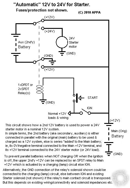
Well done tuvee! Using 2 relays could SHORT the Aux battery! (I'll complain to the APPA brotherhood, but I note their diagram above does say "Fuses/protection not shown". But I would have expected a fuse with a WARNING note ...)
VIZ: If the lower relay arm connects to +12V whilst the upper arm is still connected to +12V, that means the Aux battery is shorted - ie, the Aux +12V through the upper NC contact to "+12V" and looped back to the lower closed NO +12V contact to the Aux battery's -ve. IE - the 2 sets of relay contacts plus wiring create a short across the Aux battery.
No matter how I look at it, THEREFORE a fuse should be included in the Aux battery's +ve terminal and the relay (top contact arm).
That will even allow for a DPDT relay with sticking "upper" contacts etc. (Fuse - or breaker - ratings to be discussed later...)
Note that if the opposite occurs - ie, lower contacts still NC whilst the upper has swung to the starter +24V, that's not a problem (IMO) since it merely presents the "standard" 12V to the starter UNTIL the lower contacts swing to its +12V (then placing 24V across the starter).
Maybe that's not good for a smaller battery whilst it's supplying the full +12V cranking current, but I'll leave that till later too (we haven't discussed battery sizes and whether size matching is necessary).
The ideal solution is to have a DPDT relay, but I haven't found anything cheap or small to suit (eg, ~$100 for a Cole Hersee p/n 24452 "Motor Reversing Relay", not that its configuration is suitable (or is it?), and I only searched briefly for 80A-100A 12V DPDT relays).
Even so, IMO that Aux +12V fuse should be included.
But I still like the basic circuit. The fuse protection may be an acceptable solution to the hazard.
Or I reckon a self-resetting circuit breaker - ie, it's a temporary short due to switching delays, by the time the breakers cools and closes, the upper contacts will have opened etc, and you start as normal without having to manually replace a fuse (and spoil any getaway).
Problem with the self-resetting breaker - finding a suitable 80A rating. 50A are common (I use ~$7 weather proof ones), and I was thinking that 2 in parallel would be ok (whether 2x60A or 2x40A etc), but I'll leave that till later too. (IE - one resets before the other to full +24V starter current and re-trips, but that re-trip will take some time and the other may have also reset by then.)
The work-around if using 2 SPDT relays is to energise the lower Aux -ve relay from the starter-motor feed, but that means a temporary +12V to the starter until to lower contact switches to the Main battery +12V. And the lower relay's coil then gets 24V across it, but that can be solved with a series current limiter set to f.ex 250mA (I think that's better than a zenor circuit).
But I'll leave the lot here - including the 3(?) till laters - till later.
And I'll think of some convention of referring to the battery voltages (since +12V can be gnd or +24V etc - and that gets confusing!)
Although if the occurrence of the hazardous Aux-short is expected to be rare, or less of an issue than an interlock delay, then maybe the circuit shown is ok with the fuse/breaker.
I was also going to link the FRC3C 70A/60A relay (Jaycar, $9) which may be ok. It has a mounting flange. But I also saw a FRC6BC-1 equivalent with a mounting option - although they were USD$25 each (Picker PC-7150).
And it would be nice to know the current taken by the starter at 24V. It should be less than double its 12V current - maybe far less.
Till later. (Is that #4 "till later"?)
Posted By: tuvee
Date Posted: September 02, 2011 at 1:17 PM
Well after all that the goal posts have moved slightly. Again!
As an interesting aside oldspark, the bike's been getting a bit of a workout at the clinic and has gone through somewhere in the region of 100 engine cranks using the auxiliary battery (24v starting). As you know, there is no on board recharge for it and I have to admit to being surprised it lasted so long. I didn't measure it's output voltage at the end (although my charger showed its red charge led - red, orange, green sequence) and it took 3 hours before it regained full charge on a 4 amp charger. Even then it was not possible to discern that the battery was so low - crank performance was undiminished so I don't think it's contributing much additional current?
Anyway, I digress. The split charger unit I had in mind is not capable of switching the maximum generator output by my calculations. The generator's maximum of 400W at between 13.5 and 15V is nearly triple the 10A max of the unit..
There is an alternative which will cope with 30A but it uses the primary battery as a source to recharge the aux one. Having said that, I'm fairly sure I can use your circuit since the batteries will still be in parallel for charging and switched to series for starting.
I'd definitely want to go with a dpdt relay as I can replace the present starter relay, avoid shorting the battery and use the existing coil signal to trigger the new relay. I don't have any way of measuring the actual current draw by the motor at 24V but I believe the standard setup draws in the region of 80A at 12V which would suggest a resistance of 0.15 ohms. If so, then at 24V it could draw 160A but possibly a good bit less due to the added battery and cable resistance? What's your thoughts on this oldspark?
Even so, I'd still prefer to have plenty headroom so would look towards a 200A relay. Trouble is, I'm having difficulty sourcing even a 150A dpdt unit. I don't mind if it's a costly item either as if I'm going to do this then it needs to be done properly!
Looking forward to your thoughts on the above - they're very much appreciated.
VV
-------------
Artificial intelligence is no match for natural stupidity
Posted By: oldspark
Date Posted: September 02, 2011 at 8:00 PM
It's not yet "till later" time yet, but see 24452 Forward & Reverse Relay Module for that Cole-Hersee module I referred to.
But that looks like TWO SPDT relays to me, hence NOT adding any advantage. And its configuration may not be suitable anyway.
But unless there were some relatively cheap DPDT (so you can carry a spare?), I'd prefer the 2x SPDT solution. (Commonly available, cheaper, upscalable, carry one smaller spare, etc.)
Besides which I doubt that shorting or failure is likely anyhow. The fuse protects against shorting in the basic/simple configuration shown (carry a few spare fuses).
And if it were a common problem, it's easy to reconfigure with the interlock, but that means 12V then 24V is switched to the starter, plus a bit of circuitry UNLESS the relay coil handles 24V (ie, is 8V-24V rated).
IMO the simplest & most basic circuit is best for vehicles - especially bikes! (Yes, I own a 1972 Ducati 750 that HAD ceramic fuses etc etc, and Kwaka GPz900's with their STUPID special interlocking relay for the cooling fan (disastrous when it fails, and much simpler/cheaper/more reliable replaced with TWO SPST relays [with the bonus of semi-redundacy!]).)
I would start with the simple 2xSPST with paralleled coils AND THE FUSE, and carry spare fuse(s).
IFF that proves unreliable, then modify for the interlock version (design & diagram forthcoming...).
If a suitable DPDT were found, then cool. But size, cost, etc....
And it could still fail into the shorting mode (albeit unlikely), but hence the "essential" fuse addition.
BTW - the state of charge (SOC) should have been measurable by the OC (Open Circuit) voltage of the battery. That assumes no surface charge (ie, rested or cranked enough after charging) and a biut of time to stabilise (self-recover voltage) after a discharge.
My ROT (Rule of Thumb) is each 0.1V represents 10% discharge. (And crankers should not be discharged more than 20%, deep-cycles no more than 50% (not that you'd use a deep cycle for cranking unless it were well oversized!).)
Till later.... (LOL)
Posted By: oldspark
Date Posted: September 07, 2011 at 5:35 AM
tuvee, are you still interested in the "interlock" version?
It involves the lower relay's coil being connected to the starter motor - ie, the +24V in the original diagram. (The upper +12V to +24V relay remains as is - its coil energised by the crank/start button.)
Hence START flips the upper relay from the bike's +12V to the starter motor. The lower relay is still to GND, hence the starter gets +12V which energises the lower relay and flips it from GND to the bike's +12V, so the Aux/2nd battery is in series with the main battery (Aux/2nd -ve connected to Main +12V) so the starter gets 24V.
If the starter does not connect to +12V because the upper relay is faulty, then the lower relay does not energise so it can't short the upper battery.
The issue is that the lower relay's coil then gets 24V.
It may be possible to use a dropping resistor but that can have issues, and I think I considered connecting the coil's 85 to the Aux battery's -ve, but I think that had issues too (or did I simply not think of it? D'oh!).
Maybe the above should be reconsidered, especially with the 2 Jaycar SPDT relays in mind (known pull-in and drop-out voltages & coil current/resistance).
But otherwise....
Skip these next paragraphs and continue below if you want...
I considered a simple zenor-diode voltage clamp/regulator, but decided the easiest and most reliable is a current limiting circuit.
The current limiter is simple - a common 317 (LM317 etc) setable voltage regulator. I suggest the TO-220 package. A 2.5 Ohm 1W resistor is between its output to the coil. The ADJ terminal is connected to the end of that resistor ie, to the coil. The Input is from the "+24V" input.
That limits the current to about 500mA, but the resistor sets the current limit. (The relationship is R = 1.25V/I, eg, 1.25V/0.5A = 2.5 Ohm. It's power dissipation is VI = 1.25 x .5 = .63W => 1W.)
For 200mA, a 6.25 Ohm resistor (.25W, hence 1/4 or 1/2 Watt rating). Etc.
And probably the worst case is for a 1A relay coil, namely a 1.25 Ohm 2W (1.25W) resistor but then the 317 dissipates 14W which is about its thermal limit without heatsinking (but it has internal thermal etc protection circuitry so it will start to reduce the output current).
Its a simple 2-component circuit which is self protecting. The 317 should cost ~$3, and the resistor ~20c.
And that circuit can be placed either side of the relay coil - ie, GND side, or the hot (+24V) side. In series (of course).
It's easier seeing the pic of the 317 with the resistor, but that has yet to be done.
There are 2 considerations:
(1) the "tab" or body of the 317 is that same as its ADJust pin.
(2) the 317 might need a bypass spike protection diode (from output to input) and maybe a noise or filter capacitor.
Finished skipping? Continue here....
I can give the above more thought (and revisit the lower relay's 85 connection to Aux -ve, else a plain resistor) but I'm away for a few days...
And if you decide the original "simple" 2 SPDT relays with coils connected in parallel is ok (WITH the Aux fuse!!), then that can wait.
I reckon give the simple 2xSPDT a go. If you blow too many fuses, then we can convert later (or get a DPDT). But I suspect it shouldn't be a problem. (If the lower relay is faster than the upper, then swap the relays.)
BTW - 24V into a 12V starter should mean more current. It would be twice as much if it were resistive, but it's a motor. Hence the current should(??) be under twice the 12V current. Magnetic saturation comes into play as does "reverse generated EMF" (voltage), but I'd have to dig deep for that knowledge (I have it reasonably sussed for alternators which are simply motors in reverse, but they limit their terminal voltage - that's different to being fed a higher voltage. Plus they are AC machines - not DC... Oh the pain! Sleeping brain cells tingling back to life...)
Posted By: tuvee
Date Posted: September 07, 2011 at 1:36 PM
You have given this some thought oldspark!
I'm now quite some way out from the shore and didn't bring a paddle..
I think I prefer the first method but with a dpdt relay and fuse protection. I'm guessing that a single dpdt relay would remove any potential timing issues and the chances of a shorted battery would be less since both lines would have a much lower 'switch failure' rate (is that a valid term?) since they'd operate together. Not forgetting, of course, that I'll be sitting on top of any failures!
But this may all be moot anyway Oldspark since in my search for relays I found talk of a device which is used for what appears to be exactly what I need i.e. a series parallel switch. It seems that a number of military, heavy goods and even some cars were designed with 24v starting using 2 12v batteries charged in parallel. Need to do a bit more digging but if I can find a ready made device specifically designed to do the job then it simplifies things enormously for me (but knocks all the fun out of designing something). If you get a few minutes free sometime have a look - I'd appreciate your thoughts on whether I'm overlooking something.
Funny you should mention starting current as a friend is arguing quite strongly that the starter motor at 24v (cranking the engine at double speed) will draw the same current as it does at 12v 'because the batteries are in series'. I'm sure this is completely wrong since the work done in turning the load at double speed must be far greater and this can't be done for free. Once I find someone with a device capable of measuring such high currents I'm going to send him pics of the readings at 12 and 24.
Cheers once again and enjoy your trip.
VV
-------------
Artificial intelligence is no match for natural stupidity
Posted By: oldspark
Date Posted: September 07, 2011 at 8:50 PM
You don't need a paddle - you swim fine!
The truck devices may be physically big...
And I might see if I can test the 2xSPST, but that'll take a while to set up. Maybe next week (else next millennium lol!).
As before, 2 batteries in series means 2x the current if resistive - ie, V=IR hence I = V/R where R is constant, hence 2xV => 2xI (Amps).
But it's a motor. If it were a constant power device, then current would be halved. (ie, P=VI = 2V x I/2).
So the answer is somewhere between twice & half the current. (LOL!).
Maybe I could test that too, especially since I have a reduction (geared) starter which probably reflects a bike starter more accurately, though that shouldn't effect much. (And I have a spare!) After all, theory is one thing, reality an other. Besides, even if it takes till next millennium, that's probably quicker than my old memory (brain) cells will react!
BTW - I just use a 50A shunt (Jaycar, ~$10) which is fine for short tests. I have measured 250A starters - the tests of up to 15 seconds don't allow the "50A" shunt to heat up enough to blow.
[ The shunt - a high wattage low resistor (1mV per Amp or something, ie, R=V/I = 1mV/1A = 1 milli-Ohm) - is placed in line (series) with the starter, then the voltage drop is measured with a multimeter (DMM). ]