motorcycle alarm on scooter
Printed From: the12volt.com
Forum Name: Motorcycle Electronics
Forum Discription: Installing Stereos, Alarms, Remote Starters, Lights, Garage Door Openers and other electronics on motorcycles.
URL: https://www.the12volt.com/installbay/forum_posts.asp?tid=92608
Printed Date: March 21, 2026 at 4:44 PM
Topic: motorcycle alarm on scooter
Posted By: scoots
Subject: motorcycle alarm on scooter
Date Posted: April 06, 2007 at 2:40 PM
I recently purchased a motorcycle alarm for my 2002 Yamaha Zuma Scooter scooter. I have the wiring diagram for the alarm but am a confused on how to wire certain parts of it. This is what I have figured out so far: Pink alarm wire --> Ignition side of BLACK/ White wire
Grey alarm wire --> CDI side of BLACK/ White wire
Red alarm wire --> +ve Red battery wire
Yellow alarm wires --> Chocolate and Dark Green blinker light wires
Orange alarm wire --> ? (Lock (positive output))
Black alarm wire --> ? (Engine-stopper wire)
Blue alarm wire --> ? (Positive Electricity Starter Wire) Alarm wiring diagram: https://www.provoscooter.com/vbull/attachment.php?attachmentid=3350 Wiring diagram of the scooter's ignition are found here: https://www.provoscooter.com/shop/Zuma_Service_Manual.pdf Thanks
Replies:
Posted By: custom audio ny
Date Posted: April 07, 2007 at 7:19 PM
You forgot one important detail...to actually ask a question.. But I have several....however I got a kick out of the chocolate wires..yummy...lol orange wire for lock outputs..I don't think your scooter has doorlocks? does it? and is that what that wire is for? engine-stopper wire...what does that mean?? does it go to a starter kill? It looked to me like the starter is already interuppted with the BLACK/ white..but the terminology makes no sense to a seasoned installer..trust me. Perhaps it sends ground to the ignition coil to shut the engine down..perhaps it does that instead of a starter kill but that is NOT a safe way to prevent theft..not at all. The blue alarm wire for "positive electricity starter wire"..I would assume that goes to the starter wire...but for what? Is this a remote start as well? I don't think anyone can help unless they are familiar with that alarm system..I have never heard of it. And the wire descriptions make about as much sense as chocolate wires.. Sorry had to...lol ------------- Custom Audio
Lynbrook NY
ASE/MECP master certified
Posted By: scoots
Date Posted: April 07, 2007 at 11:21 PM
opps. well my questions is: How do I go about wiring this alarm to the ignition? The colouring scheme for the wires (i.e. "chocolate" wires) come from the scooter service manual in the link. Not my choice of terms. It's supposed to be a remote starter as well. I myself, am also quite confused as to what the terms on the wiring diagram are referring to. Also, not my choice of terms. The diagram comes with the alarm. I've been trying to understand the diagram and the terms on it for a long time and have not been able to.
Posted By: custom audio ny
Date Posted: April 07, 2007 at 11:52 PM
yeah I noticed also in the manual it says chocolate wires....does it have chicken?? and pizza colored too?? Kidding but thats funny. Anyhow..I really would like to help.I tried to understand but it is too wierd. Is there any other info or manual about the alarm?..the one diagram is a joke.....wires are crossing each other...wires go from the alarm to the key switch...those things with engine stopper and stuff. just a bit tricky. ------------- Custom Audio
Lynbrook NY
ASE/MECP master certified
Posted By: custom audio ny
Date Posted: April 08, 2007 at 12:02 AM
ok I am getting it..a little I think...look in the manual..apparently there is an engine stopper switch..find that switch and connect. positive elctric. start wire....go to the start button and connect to the wire that puts out positive when starting...the lock output is tricky....but there must be some wire that turns positive when you "lock" the scooter...do you notive any kind of lock switch on it? If so..connnect to the wire that turns + when you lock the switch...must be what they mean. everything else seems more or less straight forward..follow the diagram carefullly...if you need anymore help just give a shout. ------------- Custom Audio
Lynbrook NY
ASE/MECP master certified
Posted By: scoots
Date Posted: April 08, 2007 at 1:13 AM
There are 5 wires coming out of the ignition coloured: BLACK/ white (single wire), black, red, brown and grey I realized that I misinterpretted the drawing (reflected in original post). The black alarm wire is not the engine-stopper wire (the grey alarm wire is). I have this grey alarm wire figured out already. The alarm's wiring drawing actually shows that the black alarm wire connects to the negative battery terminal, which is also connected to the ground. Should I be connecting the black alarm wire to the black ignition wire on the scooter? Yes, there is a lock switch on the scooter's ignition. I'm not sure as to what this switch will activate. To my knowledge, all that it does is physically lock the steering column of the scooter. Another user on the Provoscooter forum called the "lock (positive output)" an "ACC Output". In this case, would it make sense to connect the orange alarm wire to the grey ignition wire (the grey ignition wire is known on Provoscooter as the "Hot Switch Wire")? If my predictions about these two wires are correct, I only have one more wire to figure out, the blue ("Positive Electricity Starter Wire") Thanks for your help Custom Audio. Wiring this alarm sure makes me hungry! 
Posted By: custom audio ny
Date Posted: April 08, 2007 at 8:54 AM
I feel kinda bad for you that you need to "perdict" what to connect. If I did that in new cars today I would be popping airbags like crazy. One of my main things about installing is to NEVER connect ANYTHING unless you know exactly what it does...and can verify with a meter. Now tru..we have a few wires that are tricky in your case. I also worry about connecting a black wire to ground AND to the ignition switch. First off...the ignition wires have no reason to be grounded...secondly..if that wire at the ign. switch was already a ground..why would you need to run it to ground?...thirdly...if it puts out any voltage..and you connect it to ground...you will blow fuses or worse...burn wires. So that diagram sucks and can cause problems because it sucks. be careful. Wish I could help more. ------------- Custom Audio
Lynbrook NY
ASE/MECP master certified
Posted By: dualsport
Date Posted: April 08, 2007 at 9:29 AM
This looks oddly similar to a system someone else was trying to install as a remote start. Don't know if it'll be any help, but maybe it'll give some additional clues in trying to figure it out.
Link
He never came back though, maybe it remote started and whisked off to parts unknown...

Posted By: custom audio ny
Date Posted: April 08, 2007 at 10:02 AM
Yeah the diagram looks better..still sucks..but better..at least it shows relays..which you would need to remote start it. Anyhow I am off to the Autoshow today...i'll look it over in detail later and see if I can help. ------------- Custom Audio
Lynbrook NY
ASE/MECP master certified
Posted By: scoots
Date Posted: April 08, 2007 at 1:18 PM
Is there anyway I can lose the remote starting feature and just use the alarm feature on my setup?
Posted By: custom audio ny
Date Posted: April 08, 2007 at 11:57 PM
Hey scoots..I am back..but it's late so I can't deal with the diagram till tomorrow. But your last question scares me...lol....just don't hook up the start wire..you really couldn't figure that??? lol/..tooo obvious I guess... Talk to you tomorrow ------------- Custom Audio
Lynbrook NY
ASE/MECP master certified
Posted By: dualsport
Date Posted: April 09, 2007 at 4:51 AM
You won't need to cut the wires (as shown by the scissors) either, since that's only needed during remote start to open up the ignition kill line.
Everything else you can hook up for the alarm functions.
The "Lock, (positive output)" is probably intended as an ignition sense line to tell the alarm when the bike is switched on, via the orange wire.
Bench test the alarm fully before doing anything, so you know for sure what it's doing with each wire.
Posted By: b2reptile
Date Posted: April 09, 2007 at 9:23 AM
It looks to me that the Pink and Grey alarm wires are a starter/ignition kill. If these wires are suppost to keep the bike from starting when the alarm is activated, then they should interrupt the Brown wire at your Zumas ignition switch. The Black wire at the ignition switch is grounded, so you should be able to hook the alarm grounds to it. And of course Red is 12v+ at the Ign switch. It is fused at 7A but that should be OK to hook the alarm red to it. You know what to do with the p. lights- That should get the alarm working. That leaves blue and orange. I agree that testing these wires with a multimeter is a good idea. I'd hook it all up on the bike and then figure out those two wires, if you need them.
Posted By: b2reptile
Date Posted: April 09, 2007 at 9:41 AM
The alarm diag says the blue wire should connect to the positive starter wire on the bike, but the Zuma starter relay gets 12v+ from the Brown Ignition wire, and is activated buy a ground from the start button. Is the blue wire an output for a remote start? Or is it an input to set off the alarm? Same with the orange wire. Input or output? Diag says to hook up to a positive output on bike. Does this tie in to what the alarm forum guys were saying?
Posted By: dualsport
Date Posted: April 09, 2007 at 7:33 PM
This is what I'd guess the function of the wires are:
Blue: Output for the remote start function; and based on their calling it a "Positive electricity starter wire", it's active high, and likely a low current output, so it'd have to be used to drive a relay. Unusual because relay drives are usually active low, grounding out when it's turned on.
Orange: Sense input to the alarm unit to tell it when the ignition is switched on. I'd check it with a bench test by measuring the voltage when the alarm is powered up, and seeing what voltage it sits at (probably 0V). Then get a 1k resistor and connect it to the wire and 12V, and see what if it goes to 12V and affects the alarm in the way you'd expect. If it's not an input but an output, using the 1k resistor should protect it from blowing up.
You could check the blue wire by measuring the voltage as you press the buttons for the remote start, and see if it outputs 12V momentarily. If not, and it appears to be sitting at 0V the whole time, check it by attaching the 1k resistor between it and 12V, and see if it goes to 0V during the remote start, indicating it's ground switched, and intended to drive a relay the usual way.
Bikes usually don't have left and right parking lights, so those outputs probably can be hooked up to the turn signal circuits.
Posted By: custom audio ny
Date Posted: April 09, 2007 at 7:45 PM
ah cool..I am glad to see some other members providing support with this alarm. It's really a shame beacuse an alarm..as well as a remote start should be a cake walk on a scooter...but since the directions have us guessing and predicting and having to perform different tests to check functions..kinda smears the icing off the cake and spits on it. But I have faith between all of us we can get help you in getting this to work without damaging anything. You will learn alot during this so it can't be a bad thing. As well you will learn patience and how not to fear what you work on...no matter what...you must believe you are smarter then what you are working on or..you have failed before you started. Just keep posting questions as you need and we will try our best. ------------- Custom Audio
Lynbrook NY
ASE/MECP master certified
Posted By: scoots
Date Posted: April 09, 2007 at 8:59 PM
Another user from the provoscooter forum also made a statement long time ago when helping someone how to install a 9 wire alarm for scooters. He had the same model of scooter as I do. Direct Quote: "The Blue wire from the alarm would go to the hot wire on the starter... (I don't use this as I have to starter with my over range tranny")" What is a over range tranny? Does this help in figuring out what the blue wire is for? His alarm diagram is attached to this post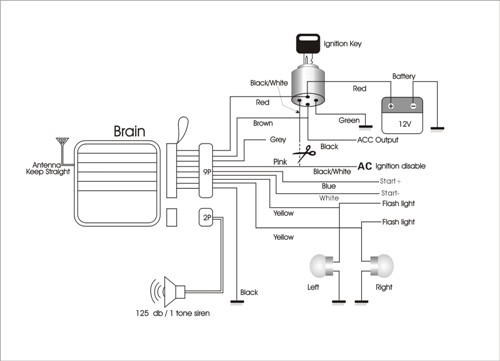 I will need to go out tomorrow and buy some resistors for the bench test. So hopefully, I'll have some more info about the blue and orange wires soon.
Posted By: dualsport
Date Posted: April 09, 2007 at 10:39 PM
"The Blue wire from the alarm would go to the hot wire on the starter... (I don't use this as I have to starter with my over range tranny")"
I'm not sure what an over range tranny is, but even if it's not a typo, it seems to be another case of English-as-a-second-language translation- maybe it's supposed to be, "I don't use this as I have to start her with my overage tranny (or granny)." Maybe he has to push start his scooter, not having electric start. (?)
The diagram he has looks pretty much equivalent except your orange wire is brown on his, and he has an additional white wire that's a negative going start wire, in addition to the blue positive going one.
If you measure the continuity of the pink and grey wires, do you see a connection between them with the alarm off? I think they're going to be open only when going through a remote start cycle, and closed otherwise.
Your bike has a simpler ignition switch and stop switch, all the connections are open when off, so you wouldn't need to connect the pink and grey wires. Not sure why that other diagram shows the pink being connected, but the grey is just left hanging.
Posted By: scoots
Date Posted: April 10, 2007 at 3:01 AM
I think that diagram has some problems as well. The grey wire in that diagram SHOULD be connected to the ignition side of the BLACK/ white wire but it is not indicated like that on the diagram. Seems like there's a general trend of crappy wiring diagrams for motorcycle alarms out there. Anyways, I'll get those bench tests done asap and post my findings. Another difference from his wiring diagram to mine is that there's nothing connecting to his green wire coming from the ignition. On my diagram, the black alarm wire connects to that location. Does this matter?
Posted By: dualsport
Date Posted: April 10, 2007 at 3:31 AM
That green wire is shown connecting to ground, which they show with the horizontal line, rather than the usual ground symbol that's more often used. You can see the battery neg terminal is also connected to ground with the same symbol.
The ignition switch on some motorcycles use the ground to disable CDI ignition modules by providing a switched ground to one of the inputs, when the switch is off. That's why they indicate a ground going to the ignition switch, which isn't normally needed with cars.
When remote starting, if the key is left in the locked position, the line needs to be opened up to enable the ignition to work, which is why they show the scissors cutting the original bike wiring, and reconnected by the alarm module connections, so that everything still works normally when the alarm is off. When the remote start is active, the alarm opens up the line to allow the engine to run.
Your particular scooter doesn't use that method, instead connecting power and ground only when it's switched on, so you probably won't need it.
|