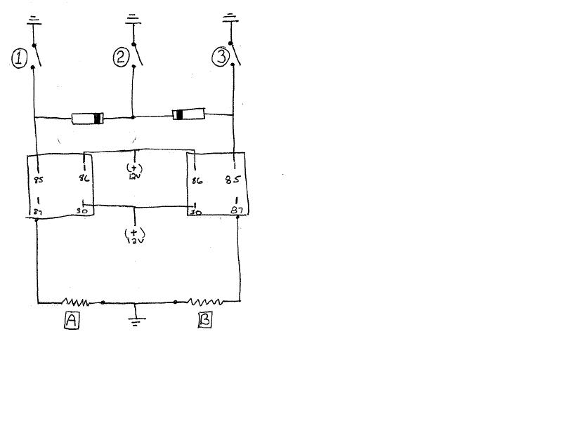
staged nitrous control
Printed From: the12volt.comForum Name: Motorcycle Electronics
Forum Discription: Installing Stereos, Alarms, Remote Starters, Lights, Garage Door Openers and other electronics on motorcycles.
URL: https://www.the12volt.com/installbay/forum_posts.asp?tid=96681
Printed Date: March 21, 2026 at 2:49 AM
Topic: staged nitrous control
Posted By: sportbikeryder
Subject: staged nitrous control
Date Posted: August 27, 2007 at 12:51 PM
Replies:
Posted By: i am an idiot
Date Posted: August 27, 2007 at 1:41 PM
Posted By: sportbikeryder
Date Posted: August 27, 2007 at 2:24 PM
Posted By: i am an idiot
Date Posted: August 27, 2007 at 4:12 PM