Passlock 2 Manual Bypass
Printed From: the12volt.com
Forum Name: Car Security and Convenience - Hot Topics
Forum Discription: Stickied topics from our Car Security and Convenience forum. Car Security and Convenience FAQs. Read First!
URL: https://www.the12volt.com/installbay/forum_posts.asp?tid=135279
Printed Date: April 20, 2026 at 12:33 PM
Topic: Passlock 2 Manual Bypass
Posted By: exley96
Subject: Passlock 2 Manual Bypass
Date Posted: November 13, 2013 at 4:31 PM
I have a 2006 Chevy Express 3500 Cube van that I am installing a remote start and alarm system in and would like to bypass the Passlock 2 without having to buy the bypass module. I have come across a few different write ups of this and I am just stuck on which of the Passlock 2 wires I need to cut to put a resistor in place. I have a Yellow wire that is "Security System Sensor" and a Tan wire that is "Security System Sense Low Ref". Does anyone know which of these two needs to be cut in order to manually bypass the Passlock 2?
Replies:
Posted By: yellow_cake
Date Posted: November 13, 2013 at 6:00 PM
Funny thing, I came to the website to ask a passlock 2 question as well.
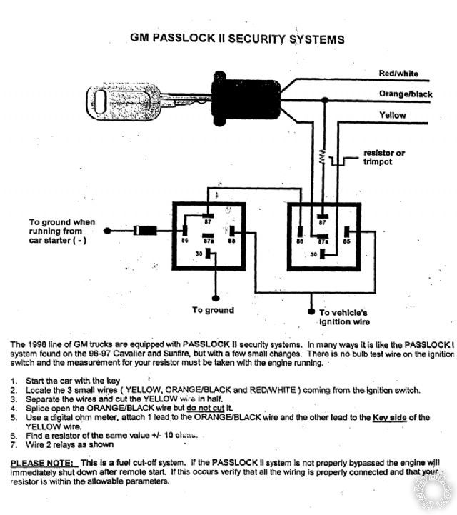
Here is the diagram, which can be found in the downloads section.
My question is, what is the purpose of the 1st relay on the left? Seems like all it's doing is amplifying the ground to the 86 of the 2nd relay (which by my observation is useless)...
Can I do without the 1st relay without any ill effects?
Posted By: exley96
Date Posted: November 13, 2013 at 6:55 PM
So the Relay on the Left has 2 grounds?? And does this setup bypass the Passlock all the time or just for remote starting? And does it matter if you get the wires from the ignition or the BCM?
Posted By: kreg357
Date Posted: November 13, 2013 at 7:09 PM
Are you looking to permanently eliminate the Passlock2 system? Cut the Yellow and solder the proper value
resistor between the Tan and the BCM side of the cut Yellow.
As for one relay or two, (-) Status Output ( GWR ) or (-) Starter relay control... There are many ways to bypass
the Passlock2 system. Take a look at DEI Tech Tip 1048 and this diagram from Audiovox :
https://documents.audiovox.com/700054.pdf ------------- Soldering is fun!
Posted By: exley96
Date Posted: November 13, 2013 at 7:43 PM
Do I cut the TAN wire or just strip the insulation back and solder one end of the resistor in line with the TAN wire? I am still making up my mind if I want to Permanently disable it or just do the Relay method.
Posted By: exley96
Date Posted: November 13, 2013 at 8:07 PM
Also if I wanted to do the first relay diagram in the DEI Tech tip 1048, my remote start/alarm doesn't have a wire output labeled "Status (-)", would I use "Armed Output (-)" or leave pin 85 of the relay with no connection?
Posted By: Ween
Date Posted: November 13, 2013 at 8:25 PM
hi,
the first relay operates upon remote starting. it stays latched throughout the run cycle of the remote start as well as when the ignition key is operated to take over operation of the vehicle.
this is probably to keep the vehicle from detecting an intermittent in the passlock II.
mark
Posted By: kreg357
Date Posted: November 13, 2013 at 9:05 PM
The Tan wire stays intact.
Your R/S system should have an output to control a bypass module. Depending on the brand, it might
be called Ground When Running ( G.W.R. ), (-) Third Ignition or the DEI term (-) Status Output.
If you are not having any of the common issues with the Passlock2 system currently, why not get a quality
bypass module and use that with the R/S? I realize that a 1/4 watt resistor is a lot less expensive than a
bypass module, but unless you are installing a R/S with alarm + starter kill, you might as well keep the
Passlock2 immobilizer system intact and functional. A data style bypass module like the ADS TBSL PL
goes for around $35. You can do the bypass using the relay and resistor method for less than $10.
Plenty of options to consider...  ------------- Soldering is fun!
Posted By: yellow_cake
Date Posted: November 14, 2013 at 1:37 AM
Thanks Ween,
You are right about the latching part, I couldn't figure that out till you told me.
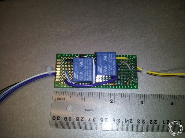
Just a photo of my diy setup. It took me about 45mins, not worth the time if you do it for a living.
My resistors are less than 1% off from the measurement of the ignition switch  !
Posted By: kreg357
Date Posted: November 14, 2013 at 4:03 AM
Yellow_Cake, nice job!  Another good use for those 10 Amp mini-relays. ------------- Soldering is fun!
Posted By: exley96
Date Posted: November 14, 2013 at 6:37 PM
Thanks everyone. Got it working perfectly. I just bypassed completely for now.
|