Here is a pictorial for anyone looking to install a remote starter into a 2005 - 2006 Chevrolet Aveo. A few bits of info :
This car was an LS model. It did not have power windows, power locks or factory alarm. It did have Automatic transmission and A/C.
This car did not have a transponder immobilizer. I believe only the LT models have an immobilizer.
Installed an Ultra Start U1175 one button remote start unit.
Disassembly :
The lower driver side dash panel is held in place by snap fasteners at the 4 corners of the rectangular panel. Just gently pull the bottom
out and then the top straight away.
The metal knee plate beneath is held in place by six 10mm bolts.
Remove the steering column cover by rotating the steering wheel 90 degrees to right and then left from TDC to expose and remove a
screw on each side. Then remove the 3 screws at the underside of the bottom cover. Separate the two halves and remove.
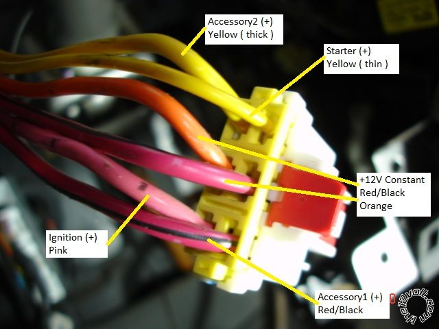
This is a picture of the ignition harness ( unplugged from the ignition switch connector, left side of steering column ).
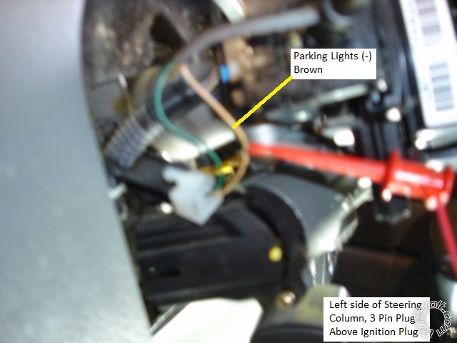
This is a picture of the (-) Parking Light wire. The connector is found just above the ignition switch on the left side of the steering column.
(Sorry for the focus.)
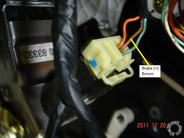
This is a picture of the (+) Brake wire found at the brake pedal switch ( top of brake pedal ).
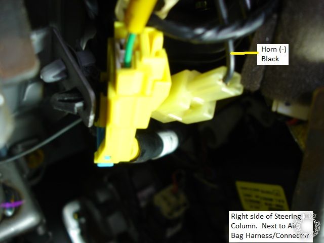
This is a picture of the (-) Horn wire found in a one pin connector on the right side of the steering column.
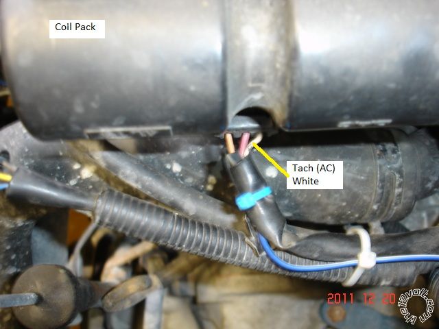
This is a picture of a Tach signal wire found at the coil pack. The signal is 1.35 V AC at idle and rises to 1.87 V AC at 2,000 RPM.
This wire can also be found inside the car, in a connector at the firewall, but has somewhat difficult access.
-------------
Soldering is fun!
Awesome. I'm going to start doing some pictorals of the installations that I do. Maybe the mods can set up a separate section with links in the vehicle wiring information database and we can start collecting a whole bunch of pictorals?? Just an idea...
-------------
Kenny
Owner / Technician
KKD Garage LLC
Albany, NY 12205
I like this idea. I will take pictures during my Mazda3 install as well. Seems like it could be beneficial for others in the future.
-------------
-Mike
98 Ford SVT Contour
09 Mazda3
05 EB Expedition
97 Civic DX
Nice write-up and pictures!! Thanks much. I agree with offroadzj, a section with pictorials would be awesome!!
Very nice. Pictorials are definite help for noobs.
Keep them comming.
damn i should have taken pics of the 2012 mazda 3 i did today.
easy car to take for btw. Alarm/RS 1 hour.
-------------
Ted
2nd Year Tier 1 Medical School
Still installing as a hobby...pays for groceries
Compustar Expert
A couple notes on these cars:
Parklights can be either brown or white at the switch
brakelights are in drivers kick, brown in the bottom white plug, E-brake is thinner brown in the same plug
doorpin is GREEN / WHITE in a black plug in drivers kick
tach is easiest to get in the grey connector coming throught the firewall, simply unplug and the harness comes within easy reach, white wire pin 15 (there can be three white wires, test accordingly)