2009-2011 Toyota Yaris Remote Starter Pictorial
Printed From: the12volt.com
Forum Name: Car Security and Convenience - Alarm/Remote Start Pictorials
Forum Discription: Installer submitted Alarm, Keyless Entry, and Remote Start Pictorials from our Car Security and Convenience forum.
URL: https://www.the12volt.com/installbay/forum_posts.asp?tid=129997
Printed Date: May 10, 2026 at 2:30 PM
Topic: 2009-2011 Toyota Yaris Remote Starter Pictorial
Posted By: kreg357
Subject: 2009-2011 Toyota Yaris Remote Starter Pictorial
Date Posted: January 02, 2012 at 2:53 PM
This is a pictorial for the 2009 - 2011 Toyota Yaris for a basic remote starter install. These pictures are
from a 2011 5 door with no power locks or windows. This car did have Automatic Transmission and A/C.
No transponder based immobilizer was installed.
Disassembly : Remove the drivers lower dash panel by pulling at the top - straight away. There are 6 retaining clips.
The panel is hinged at the bottom and folds down. Open the storage bin and remove by squeezing the top sides
in and pull out. Then pull the bin straight away at the bottom hinge exposing the Dash Fuse Box.
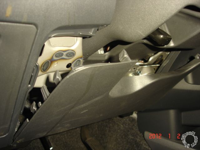
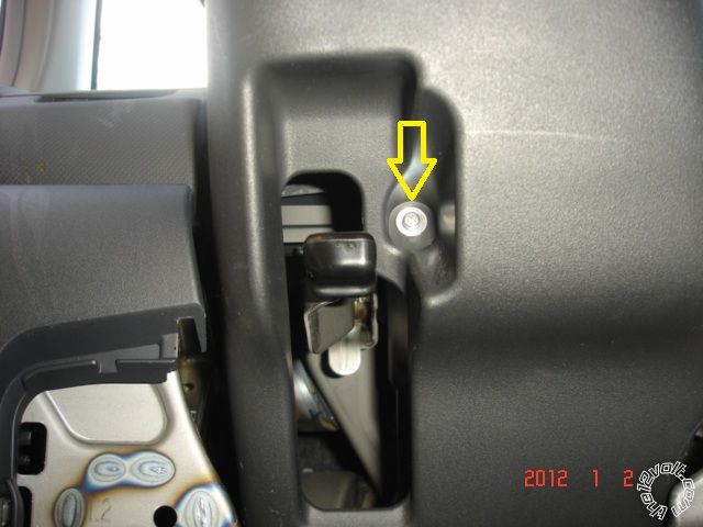
Remove the lower Steering Column cover by removing one Phillips screw at the bottom and two Phillips screws at
3 and 9 o'clock by rotating the steering wheel right & left.
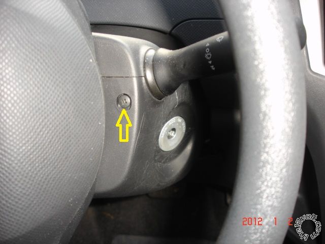
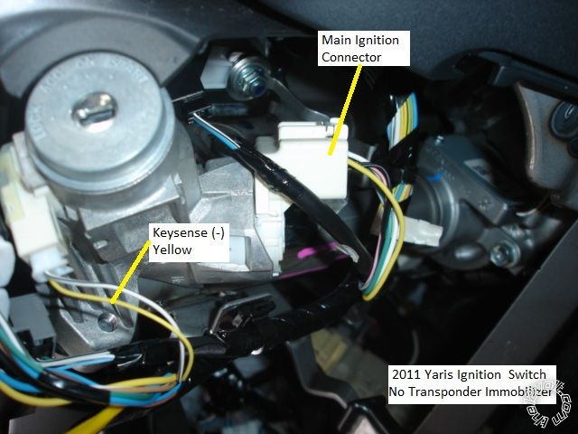
Picture of Ignition Switch on right side of steering column with lower cover removed.
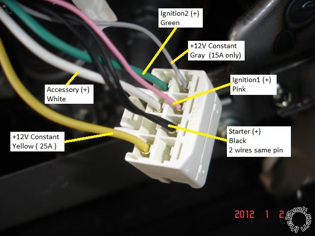
Picture of Ignition connector. Small gauge wires.
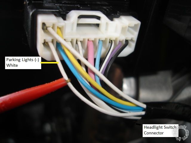
Picture of Headlight switch connector in steering column.
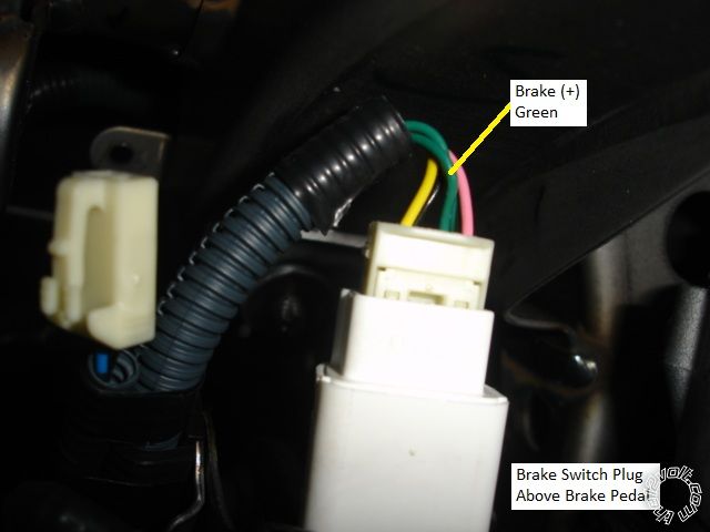
Picture of Brake Pedal Switch connector above brake pedal.
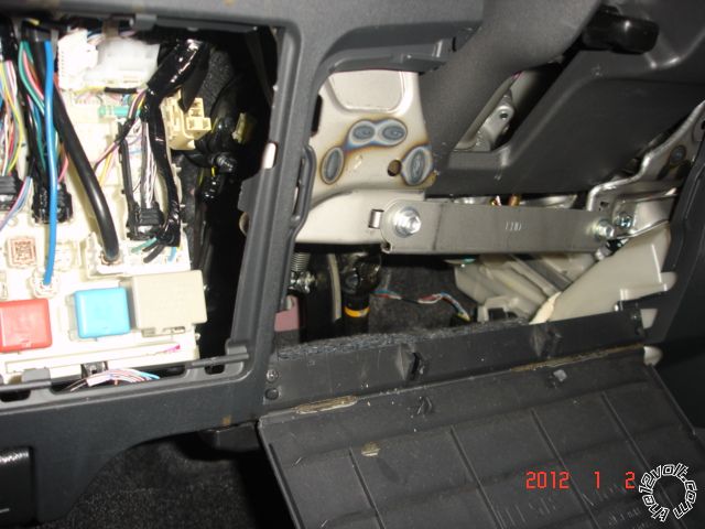
Picture of Dash Fuse Box.
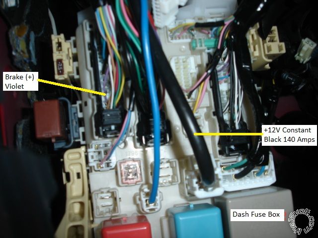
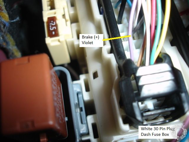
Picture of Brake(+) at Dash Fuse Box. Close-up.
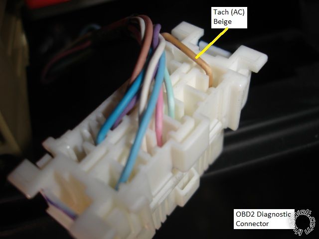
Picture of OBD2 diagnostic connector. The Tach wire is at Pin 9 and can be Beige or Light Green. Tach is also available
at any Fuel Injector, non-common color wire.
------------- Soldering is fun!
Replies:
Posted By: metz35
Date Posted: January 02, 2012 at 3:34 PM
Nice! +1
Posted By: ziggyb222
Date Posted: January 02, 2012 at 4:37 PM
Very nice!!!!! Thank You
Posted By: yarisyeti
Date Posted: January 17, 2012 at 11:21 PM
Does the yaris need a transponder based immobilizer?
Posted By: kreg357
Date Posted: January 20, 2012 at 3:04 AM
This particular vehicle did not have a transponder based immobilizer system. As shown on the Ignition Switch picture ( 5th photo down from top ) no antenna ring was in place in the groove at the end of the key cylinder. This was a very base model. All bypass manufacturers do list modules for this vehicle, so they are out there.
-------------
Soldering is fun!
Posted By: sansag13
Date Posted: May 07, 2012 at 3:24 PM
Hi,
Can you please let me know which is "Horn" wire? I am trying to hook up horn wire of remote starter (with remote lock/unlock) with yaris but have a hard time to find horn wire.
Thanks,
------------- :D
Posted By: kreg357
Date Posted: May 08, 2012 at 11:59 AM
Sorry, I didn't get a photo of that wire. Customer didn't want horn
confirmation. Here is the location from several wire guides :
Bulldog Security :
HORN BLACK (-) @ HORN SWITCH or DASH FUSE BOX, (WHITE, 32-Pin Plug(E) Pin 18
Ready Remote :
Horn Trigger black (-) horn switch or dash fuse box, white 32 pin plug (4E), pin 18
Audiovox :
Horn LIGHT GREEN (-) AT FUSE PANEL BEHIND DRIVERS SIDE OF DASH
ALSO BLACK IN STEERING COLUMN HARNESS
Omega :
OEM Horn BLACK (-) HORN SWITCH
Should be pretty easy to locate. Set Digital Multi Meter to 20V DC, connect Red
lead to +12V constant and Black lead to suspect wire. When horn button is pressed,
the DMM should read +12V. The steering column should be easy to access and
find this wire. ( It won't be in the Headlight Connector pictured above and stay
away from any Yellow connectors or Yellow harnesses - air bag.) ------------- Soldering is fun!
Posted By: howie ll
Date Posted: May 09, 2012 at 5:47 PM
I'm actually surprised at no immobiliser. The Yaris comes from the UK and as I've said before, they all have immobilisers for Europe.
Funny I've never seen one in the UK without power windows and locks.
-------------
Amateurs assume, don't test and have problems; pros test first. I am not a free install service.
Read the installation manual, do a search here or online for your vehicle wiring before posting.
Posted By: sansag13
Date Posted: May 22, 2012 at 8:33 AM
Thank you Kreg.. Horn connection worked out as per your information.. Thank you everybody for helping this novice..
-------------
:D
Posted By: rhendy87
Date Posted: October 18, 2012 at 4:43 AM
Hi guys,
i need a little help over here.
Can you please inform me where is the wire for
1.Oil Circuit detection
2.Cut oil and electric circuit off.
i am currently trying to install a remote start.I cant seems to find these 2 wire.
Any help is greately appreciated.
regards,
Rhendy
Posted By: howie ll
Date Posted: October 18, 2012 at 1:49 PM
No you don't. Any unit that picks up "engine running" sense has to be thrown in the bin it's garbage.
It will probably never work and damage your vehicle.
The instructions are as bad as the product the second question refers to either the ignition which should NEVER be cut for safety reasons or the starter wire.
-------------
Amateurs assume, don't test and have problems; pros test first. I am not a free install service.
Read the installation manual, do a search here or online for your vehicle wiring before posting.
Posted By: rhendy87
Date Posted: October 19, 2012 at 1:35 AM
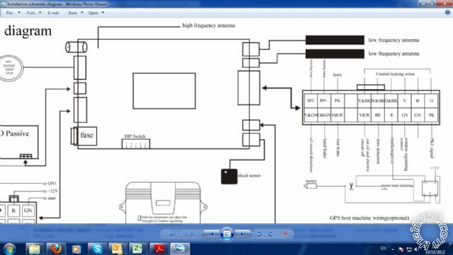
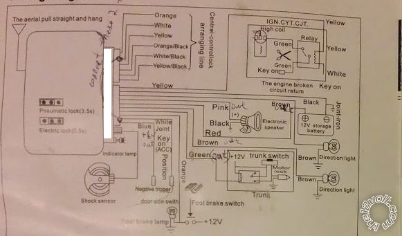
i've attached the wiring diagram.Can you please take a look at it.
the ignition wire is doesnt need to be cut at all.just the other module shown in the picture.
Please tell me what do you think
Posted By: howie ll
Date Posted: October 19, 2012 at 1:44 AM
Can't read it, my first advice still stands.
-------------
Amateurs assume, don't test and have problems; pros test first. I am not a free install service.
Read the installation manual, do a search here or online for your vehicle wiring before posting.
Posted By: rhendy87
Date Posted: October 19, 2012 at 2:13 AM
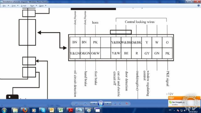
i post a clearer picture.
from my understanding,the Oil circuit detection & cut oil and electric circuit off is dangerous to jumper it or even mess with it?
regards,
Rhendy
Posted By: howie ll
Date Posted: October 19, 2012 at 2:28 AM
Absolutely. Only ever cut starter wire at ignition switch.
Steering direction = indicators you've got to laugh.
Follow those instructions and destroy your car.
-------------
Amateurs assume, don't test and have problems; pros test first. I am not a free install service.
Read the installation manual, do a search here or online for your vehicle wiring before posting.
Posted By: rhendy87
Date Posted: October 19, 2012 at 10:45 AM
ok.thnx for your advise..
i know it might be risky..
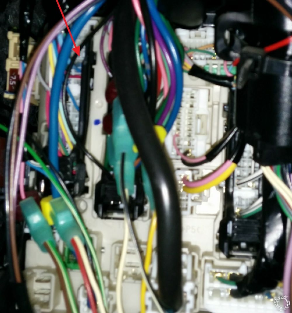
but by any chance..could you please help me pinpoint where the cabel is?
Posted By: howie ll
Date Posted: October 19, 2012 at 10:57 AM
My only advice if you have to ask that sort of question is don't do it take it to a pro.
If you can't find the starter wire .....
-------------
Amateurs assume, don't test and have problems; pros test first. I am not a free install service.
Read the installation manual, do a search here or online for your vehicle wiring before posting.
Posted By: rhendy87
Date Posted: October 19, 2012 at 11:38 AM
i do know where the starter wire(ignition wire) are located at.
its located under the steering wheel.
its just that 1 wire im frustrated at.cant seem to find it.
Posted By: kreg357
Date Posted: October 19, 2012 at 11:44 AM
Can the "Oil Decision" wire / circuit be programmed for a Tach Signal? Using an oil pressure sending unit signal to tell if the engine is running is a very poor way of handling it. 
On the brighter side, the unit does have built in door lock relays...  ------------- Soldering is fun!
Posted By: rhendy87
Date Posted: October 19, 2012 at 12:05 PM
hi kreg,
i think that oil decision wire could refer to fuel injector.the supplier told me that it is related to fuel pump.
Posted By: rhendy87
Date Posted: October 21, 2012 at 8:41 AM
i found the wire and the module is working just fine.
the fuel pump wire is more for the remote start thing.
thankss
Posted By: jolietjim
Date Posted: November 08, 2014 at 6:57 PM
Seeing how the IG 1 & 2 on the ignition switch harness are small gauge wires would you recommend installing your remote start 12V constants on the large black main feed in the under dash fuse box or on the ignition switch connector wires?
Posted By: kreg357
Date Posted: November 08, 2014 at 7:39 PM
That is the way I usually do it. Run the R/S's +12V constant input power feeds to the thick Black +12V constant wire at the fuse box. While the ignition switch plug has a 25 Amp and a 15 Amp +12V constant wire, trying to correctly "load balance" the R/S's +12V input wires could be difficult and result in vehicle blown fuses. Much safer to go to the thick Black wire.
-------------
Soldering is fun!
Posted By: jolietjim
Date Posted: November 08, 2014 at 7:58 PM
Thank you for the fast reply, have a great weekend.
Posted By: jgarcia1925
Date Posted: November 11, 2014 at 1:17 PM
hate to bring up more questions to this older thread, but im working on one of these soon. the 07 yaris that i will be doing the install has no power locks, and im adding those on, anyone have pictures of anybody who has done these before, they have cable locks which is why i ask, or any suggestions would be great. also, i dont think this will need any bypass since the keys are metal, but do we still need to hookup the keysense for anything?
the help would be great! thanks!
jesus
Posted By: windog
Date Posted: October 21, 2016 at 11:04 PM
I have never seen a remote start installation requiring the information you are asking for. Why would you need oil control info for a simple install? is this some special equipment?
Posted By: howie ll
Date Posted: October 27, 2016 at 5:59 PM
Windog, some cheap and nasty products require oil pressure sensor to detect tach, very unreliable and if a prouct mentions it, avoid like the plague!
-------------
Amateurs assume, don't test and have problems; pros test first. I am not a free install service.
Read the installation manual, do a search here or online for your vehicle wiring before posting.
Posted By: hoanayang
Date Posted: February 26, 2017 at 7:38 PM
Thank you!
1. I want to connect to the horn, but I found I don't have pin 18 black wire. what should I do when I don't have that wire to split out?
2. My alarm has one wire needs to connect to the door sensor. However, I think yaris 2009 has 4 different wires for each door, pin 21, 24,5,and 20 (30 pins plug). How can I connect them to one wire only in the alarm system? Or I was looking at the wrong wire?
Thanks!
Camille
Posted By: kreg357
Date Posted: February 27, 2017 at 7:19 PM
Here are some other locations / possibilities for the Horn wire :
Audiovox :
Horn LIGHT GREEN (-) AT FUSE PANEL BEHIND DRIVERS SIDE OF DASH
ALSO BLACK IN STEERING COLUMN HARNESS
Omega :
OEM Horn BLACK (-) HORN SWITCH
Should be pretty easy to locate. Set Digital Multi Meter to 20V DC, connect Red
lead to +12V constant and Black lead to suspect wire. When horn button is pressed,
the DMM should read +12V. The steering column should be easy to access and
find this wire. ( It won't be in the Headlight Connector pictured above and stay
away from any Yellow connectors or Yellow harnesses - air bag.)
You should combine all 4 door trigger wires to make one alarm trigger input using
1N4001 diodes. Here is a generic diagram from Bulldog Security :
https://diagrams.marktoonen.nl/DOWNLOADS/24464_NEON_(-)%20NEGATIVE%20DOOR%20PIN%20ISOLATION%20CIRCUIT.pdf
-------------
Soldering is fun!
Posted By: hoanayang
Date Posted: April 02, 2017 at 10:49 PM
Thank you!
Today I set up everything other than the door trigger because I am facing some diode issues
My alarm negative trigger line sends out +4.76v all the time. When I connect it to one door sensor, everything works correctly, and I see it becomes 0v, and the alarm door trigger is triggered.
However, all four doors have their own sensor wires. Therefore, I bought four 1N4004 diodes to separate them. After I use them, the door trigger never been triggered.
I removed all and use only one diode to one door only, instead of 0v, I see it become 0.7v, I guess that's the reason the door sensor cannot trigger door trigger anymore with a diode in between. How can I solve this problem? And can I just connect all four wires to one door trigger wire without diode?
Thanks a lot!
Posted By: windog
Date Posted: April 03, 2017 at 1:20 AM
The door trigger polarity has to be determined before connections are made. If the door trigger wire reads negative when the door is open then you have to connect the trigger wire on the vehicle to the negative trigger wire on your remote starter or alarm device. Do the reverse process if the door trigger tests positive polarity when the door is open. You should not connect the wires without diode connection, The diodes are for protection of your remote starter or alarm device and for your safety too. You could start a fire in the car if there is feedback from your door pin to the vehicle's circuitry.
Posted By: hoanayang
Date Posted: April 03, 2017 at 1:39 AM
Thank you for the quick reply!
May I know more detail about how to determine negative or positive reading? The reason I am asking because door wire is only one wire (pin 22 for the driver side, and pin 5 for the passenger side)
when I use the multireader, I connect red terminal to pin 22, and the black terminal to the car body. I got the value of 4.97V when the door is close. when the door is open I got 0V. (the weird thing is that about 30 seconds after the door closing, the reading from 4.97V becomes to 1.98V, but this doesn't effect the result with a diode)
I also did the test for the alarm door trigger wire to the car body, it is constaint of 4.76V
When I connect the alarm door trigger wire to pin22, when the door open, it become 0V too and the door trigger is triggered correctly. However, if I have a diode in between, the reading is 0.7V, and the door trigger is not triggered.
Thank You!
Posted By: kreg357
Date Posted: April 03, 2017 at 6:05 PM
With a Digital Multi Meter you must use a kind of reverse logic. You are looking for a ground potential when the door is opened. It takes a bit of thought to figure how to read this ground. Basically you must look for a ground path that will complete a simple circuit. If you place the DMM Red lead on the batterys' positive terminal and have the Black lead touching nothing, the meter will read 0V. When you touch the Black lead to the negative battery terminal ( or any solid chassis point ), the DMM will read +12V. That is the way to test. Connect the Red lead to +12V constant and the Black lead to the suspect Door Trigger wire. With the door closed you should get 0V. When the door is opened, the Black lead now has path back to the battery and the DMM will read +12V.
Kind of like that old brain teaser, where you are walking down a road and come to a fork. One way leads to your destination, the other way goes in the wrong direction. At the fork are two brothers. One always tells the truth and the other always lies. You get to ask one and only one question of one brother but you don't know which one is which. What is your question that will get you heading down the correct path?
-------------
Soldering is fun!
Posted By: hoanayang
Date Posted: April 03, 2017 at 6:33 PM
thank you. I will test it tonight when I get home.
By the way, I read all document, and they all mention negative door trigger. does that mean I have to use negative trigger wire in the alarm?
Door Trigger Negative Wire (-): Pink
Door Trigger Negative Wire Location: At Fuse Panel Behind the Driver Side of the Dash
modified life web /2009-toyota-yaris-auto-alarm-wiring-instructions/
I tried the horn, the document said it is negative, but my alarm produce positive so I need to use a relay to convert it back to negative. then it works without any issue. I wonder is the same way alarm trigger?
thanks
Posted By: hoanayang
Date Posted: April 03, 2017 at 10:36 PM
very interesting. I follow your step.
When the door is open:
- DMM red to battery positive, DMM black to the door trigger wire = 12.65V
- DMM black to battery negative, DDM red to the door trigger wire = 0V
When the door is close:
- DMM red to battery positive, DMM black to the door trigger wire = 0V
- DMM black to battery negative, DDM red to the door trigger wire = 5.21V
Questions:
Thanks a lot!
|