2010 Toyota Tacoma Remote Start Pictorial
Printed From: the12volt.com
Forum Name: Car Security and Convenience - Alarm/Remote Start Pictorials
Forum Discription: Installer submitted Alarm, Keyless Entry, and Remote Start Pictorials from our Car Security and Convenience forum.
URL: https://www.the12volt.com/installbay/forum_posts.asp?tid=130004
Printed Date: May 23, 2026 at 9:39 PM
Topic: 2010 Toyota Tacoma Remote Start Pictorial
Posted By: offroadzj
Subject: 2010 Toyota Tacoma Remote Start Pictorial
Date Posted: January 02, 2012 at 8:40 PM
Vehicle: 2010 Toyota Tacoma Automatic
Starter: Python 580
Bypass: Key-Override-All (Fortin)
Disassembly:
- Remove Door sill panel and driver kick panel
- Pop off small plastic "door" on right side of knee bolster and remove (2) 10mm bolts on either side of bolster
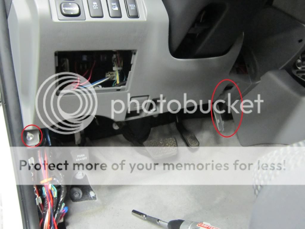
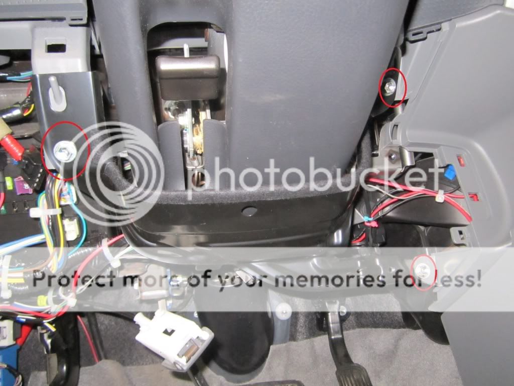
- Remove (3) 10mm bolts on metal support bracket. Lift up and out to remove bracket.
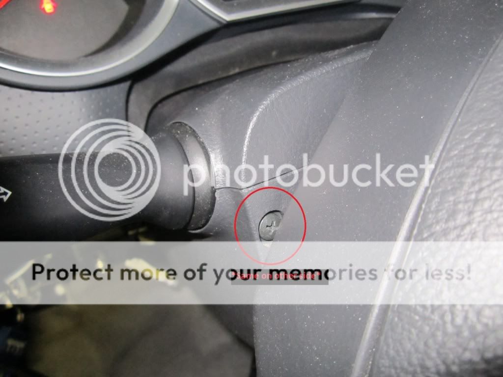
- Remove (2) Phillips head screws behind steering wheel and remove lower steering column plastic.
Installation:
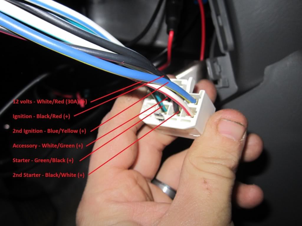
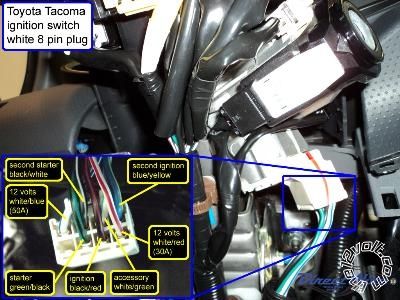
- Main ignition harness at ignition switch
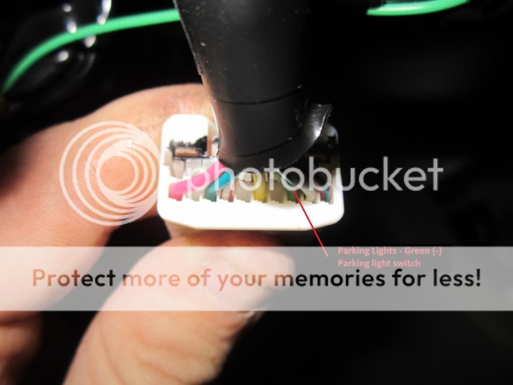
- Parking lights (-) at light switch
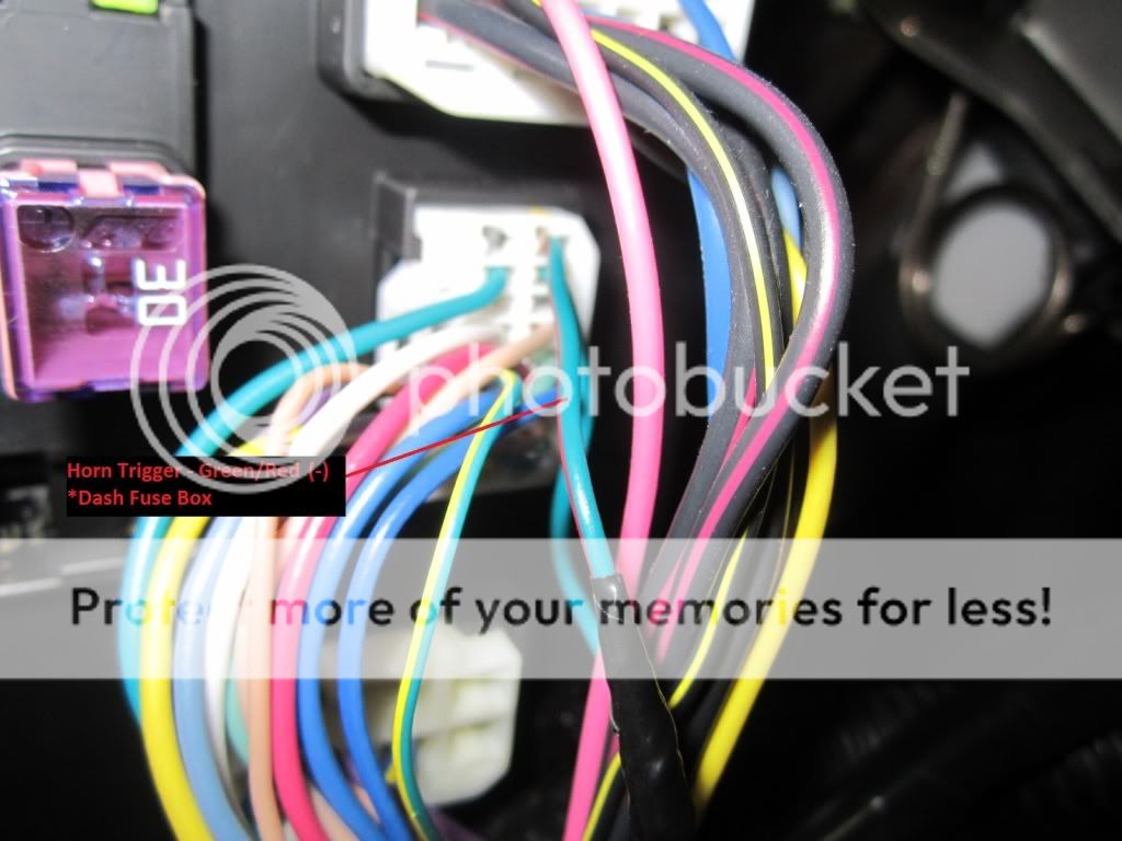
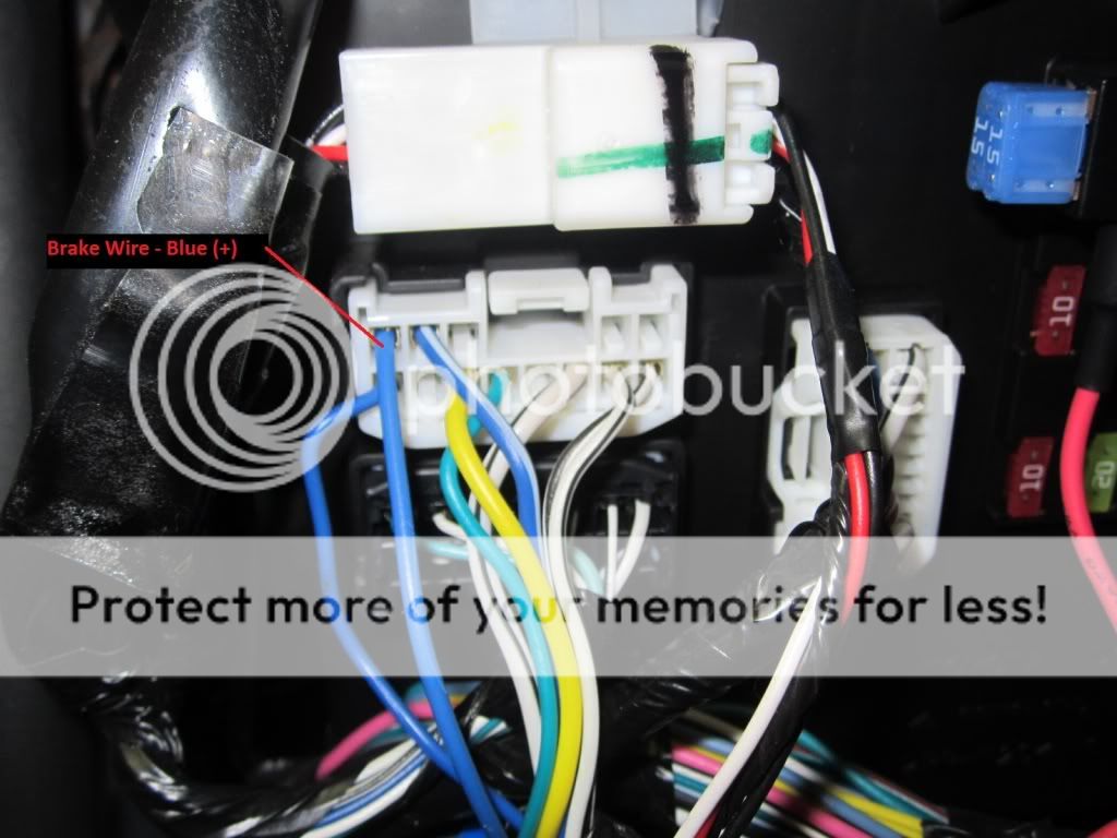
- Brake switch and horn at front of fuse panel
- Door locks found in Driver Kick panel coming from driver door.
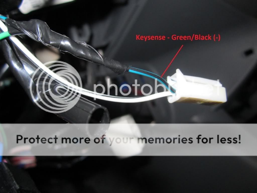
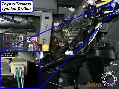
- Keysense at ignition switch
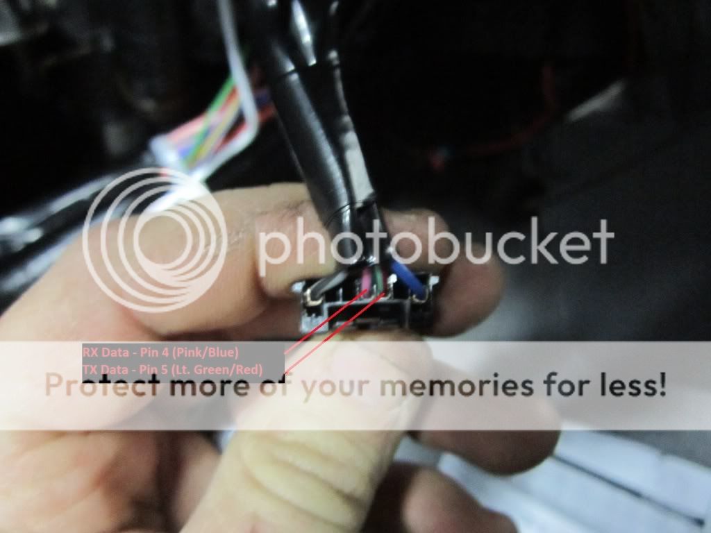
- Data wires found at ignition switch
No pictured:
- Tach signal found at OBD connector
- Hood pin was added for installation. ------------- Kenny
Owner / Technician
KKD Garage LLC
Albany, NY 12205
Replies:
Posted By: rascal737
Date Posted: January 16, 2012 at 2:14 AM
a couple of questions for a python 574 remote start install... I have a 2009 toyota tacoma, auto, dbl cab
1: i don't have starter 1 and starter 2 wires for my remote start, but i do have starter input and output wires.....do i connect them to the starter 1 (GREEN/ black) and starter 2 (BLACK/ white) wires?
2: the remote start has an onboard flex relay....(30) flex relay output (carside of ign, acc or starter wire) do I connect my ign 2 wire (blue/white) to this output on the module?
Posted By: kreg357
Date Posted: January 16, 2012 at 5:33 AM
2009 thru 2012 should be the same.
Ans 1.) No. H3-4 goes to Starter1. H3-5 is optional - if you want starter kill, cut the Starter1 wire, connect H3-4 to vehicle side & H3-5 to key switch side. To power the Starter2 wire an addition 30/40A SPDT relay controlled by H2-18 is required.
Ans 2.) Yes. Connect H3-7 to Ignition2. Factory default programming sets this output as IGN2.
Be sure to connect H3-2, H3-6, H3-9 and H1-1 to +12V constant. ------------- Soldering is fun!
Posted By: rascal737
Date Posted: January 16, 2012 at 2:11 PM
thanks kreg357.....
so what your saying is (just so that i'm 100%), answer 1:) either option (starter kill or not), I still need another relay......pin 86 and 87 to 12V+, pin 85 to H2/18(starter output), pin 30 to vehicle starter 2 wire (BLACK/ white) and pin 87a open (NC)
and yes wires H3/2, H3/6, H3/9 and H1/1 are connected to 12V+ constant
I really appreciate your help
This is my first remote start install so I'm taking it really slow, locating, testing wires, routing, and temporarily connecting to make sure all routing is hidden and wires are long enough
Posted By: kreg357
Date Posted: January 16, 2012 at 4:19 PM
Yes,exactly right. If you want Starter kill / anti-grind, cut the vehicles Starter1 wire and connect H3-4 and H3-5 to the correct sides of the cut wire.
The extra relay for Starter2 wiring is correct, too. Just add a fuse to the Pin 86 / 87 +12V connection.
Doing great so far! Make sure you solder all connections and insulate with quality electric tape.
Bypass module?
------------- Soldering is fun!
Posted By: rascal737
Date Posted: January 16, 2012 at 7:35 PM
kreg357.... thanks again for the confirmation
yes all connections soldered and taped up
bypass module is an expresskit pkall, it's installed and programmed with no issues, i think (got the 10 flashes on the module and led did not come back on)......should be good to go.
I just have to wire up the starter 2 relay, program the unit for automatic (default is manual transmission) then test.
Posted By: rascal737
Date Posted: January 18, 2012 at 3:25 AM
Kreg357, thank you very much!!!
I got the relay hooked up, tested the system and it WORKS!!!
It's only a rough routing right now, so only thing outstanding is to do the final routing of the remote start wiring, soldering a few wires and putting the trim panels back.
Again THANK YOU!!
Posted By: afridihamid
Date Posted: December 26, 2012 at 11:18 PM
My R/S main harness has two 12volt constant wires fused at 30amps each. Do you recommend fusing them down (perhaps to 15A or 20A each) since the 12v constant in the truck's ignition harness is rated at 30amps? (Maybe Kreg can chime in on this subject, lol).
Also if your recall, how hard was routing the wire through the firewall for the hood switch? And which area did you install the hood switch?
Thanks for the write up!
Posted By: joeschmuck
Date Posted: December 30, 2012 at 4:13 PM
I'm on a mission to install my third remote starter but this time on my truck and I'm purchasing one that is a bit better quality than my previous ones.
I have a 2010 Tacoma (there is a dot on the key indicating the imobilizer is built in) that I am looking at installing the Python 513 or possibly the Python 524. The latter has bi-directional communications so I'd know for sure the vehicle is running or not yet the first one is small and simplistic.
My objectives are:
1) Find out how to wire up the A/C or Heater to automatically turn on to their proper setting when the car is started. How many times have you run your car in the cold just to find out you left your cabin temp either off or not in the hot position? I have so I'd like to make this automatic.
2) Ensure I only have one key fob with my truck keys.
3) Get a wiring diagram for installing both devices so I can plan the installation on paper before purchasing.
4) Purchase the Python kit and Bypass kit (if required).
So my questions to the forum group are:
1) Where can I locate installation instructions for these two Python devices? I was unable to locate anything from Python themselves other than user guides.
2) Both units enable the defroster below 55 F. I would use this as the trigger for determining if I should Heat the inside of the truck, or when it's over 55 F then I'd Cool the inside of the truck. And to be honest, I wouldn't start the truck from 50F to 78F. This means I'd have to come up with some circuit that when the remote starter was used, it would engage the cab fan to High, if defroster is on then I'd have to establish heat and widow defrost. If no defrost I'd have to establish Max A/C and Dash Vents. This doesn't sound too difficult for me but I'd have to use either Solid State Relays and try to locate a wiring harness to plug into the control panel as I'm certain it's not only a few simple relays. If someone could point me to a wiring diagram for the A/C and Heat control panel that would also be appreciated.
I don't feel this is too ambitious of a project but the A/C and Heat are important and if I can use a wiring harness so I can build a simple plug-in device, that is what I want to do.
I will take photos and post my results including the schematics once I'm done.
Thanks,
Joe
EDIT: I have located the installation manuals. Go figure the proper Google search would show them. I also grabbed the Xpress Kit PKTX instructions.
Posted By: cruzs2013sr5
Date Posted: March 24, 2013 at 8:41 AM
Hello everyone. I just signed up to this forum. WOW! Lots of information. I was just wondering if anyone knew if this thread, (wiring) how-to was at all similar to the 2013 Tacoma. I was just wondering if it was different. I was thinking of buying the Pyton 574 with remote start for my truck. Thanks.
-------------
Cruzer
Posted By: cruzs2013sr5
Date Posted: May 04, 2013 at 2:58 PM
cruzs2013sr5 wrote:
Hello everyone. I just signed up to this forum. WOW! Lots of information. I was just wondering if anyone knew if this thread, (wiring) how-to was at all similar to the 2013 Tacoma. I was just wondering if it was different. I was thinking of buying the Pyton 574 with remote start for my truck. Thanks.
Anyone?
------------- Cruzer
Posted By: kreg357
Date Posted: May 04, 2013 at 4:07 PM
According to Bulldog Security, they are the same. Here is a link to their wire guide listing :
https://diagrams.marktoonen.nl/printlist.aspx?MakeID=2&ModelID=20135
Check your ignition key for the "G" stamp.
------------- Soldering is fun!
Posted By: cruzs2013sr5
Date Posted: May 04, 2013 at 6:30 PM
Thank you.
-------------
Cruzer
Posted By: tonanzith
Date Posted: May 04, 2013 at 10:53 PM
12 Volts WHITE/ red (30A) + ignition switch, white 8 pin plug, pin 5
Second 12 Volts WHITE/ blue (50A) + ignition switch, white 8 pin plug, pin 4
Starter GREEN/ black + ignition switch, white 8 pin plug, pin 7
Second Starter BLACK/ white + ignition switch, white 8 pin plug, pin 3
Ignition BLACK/ red + ignition switch, white 8 pin plug, pin 6
Second Ignition blue / YELLOW + ignition switch, white 8 pin plug, pin 1
Third Ignition N/A
Accessory WHITE/ green + ignition switch, white 8 pin plug, pin 2
Second Accessory N/A
Third Accessory N/A
Keysense GREEN/ black - ignition key switch, white 2 pin plug, pin 1
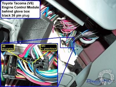
Data Bus pink/green (RX), lt. GREEN/ red (TX) data Transponder Key Amplifier, black 7 pin plug, pins 4 and 5
Can Bus High yellow/black data data link connector, white 16 pin plug, pin 6
Can Bus Low blue/white data data link connector, white 16 pin plug, pin 14
Can Bus Sw N/A
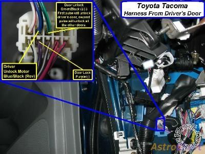
Power Lock blue/white - driver kick, gray 10 pin plug, pin 6
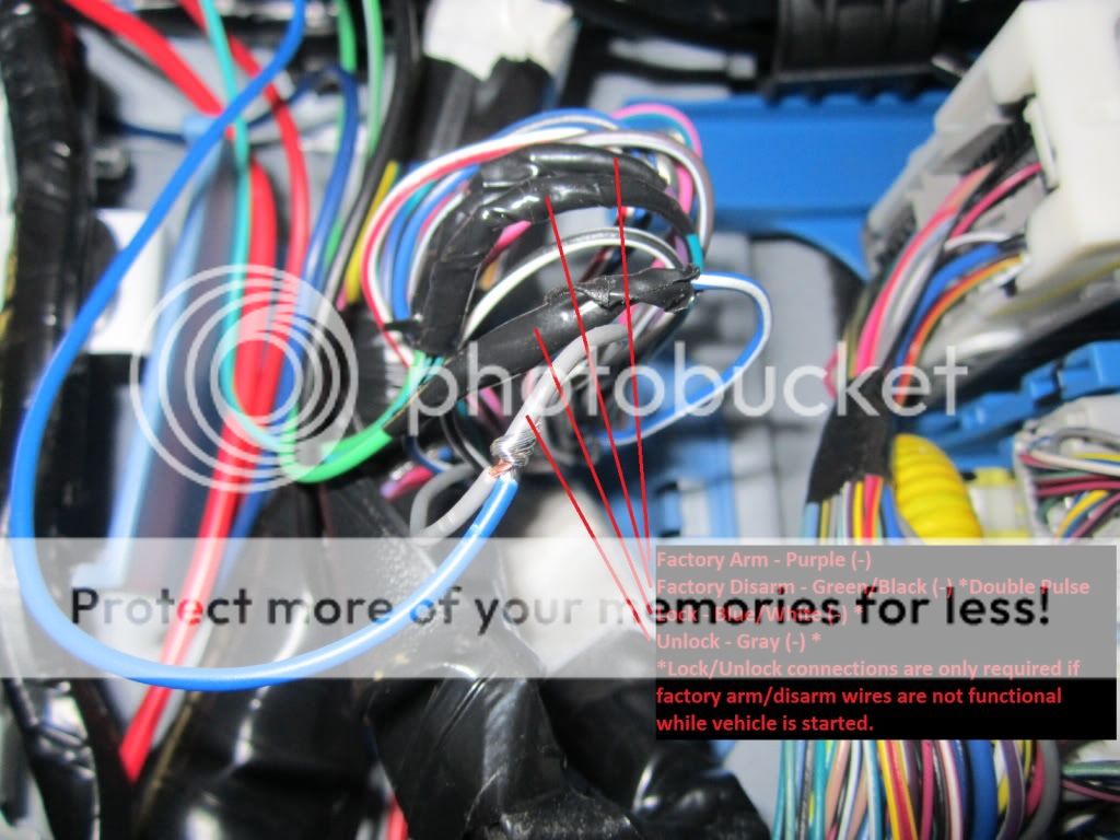
Power Unlock gray - driver kick, gray 10 pin plug, pin 7
Lock Motor blue/red 5 wire driver kick, white 12 pin plug, pin 10 or black 8 pin plug, pin 6
Driver Unlock Motor blue/black 5 wire driver kick, gray 10 pin plug, pin 9
Passenger Unlock Motor blue/black 5 wire dash fuse box, rear, white 24 pin plug (1H), pin 5
Parking Lights (-) green - headlight switch, white 20 pin plug, pin 18
Parking Lights (+) green + dash fuse box, white 13 pin plug (1D), pin 10
Hazards RED / white - hazard switch, white 14 pin plug, pin 9
Turn Signal (Left) yellow (F); yellow (R) (common on models w/o DRL) + dash fuse box, wht 11 pin plg (1B), pin 7; wht 13 pin plg (1D), pin 11
Turn Signal (Right) lt. blu (F); blu/wht (R)(common on models w/o DRL) + dash fuse box, wht 11 pin plg (1B), pin 5; wht 13 pin plg (1D), pin 4
Headlight pink - headlight switch, white 20 pin plug, pin 20
AutoLights N/A
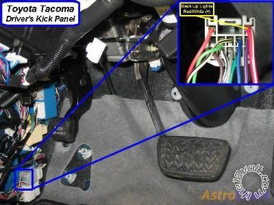
Reverse Light red + driver kick, gray 12 pin plug, pin 1
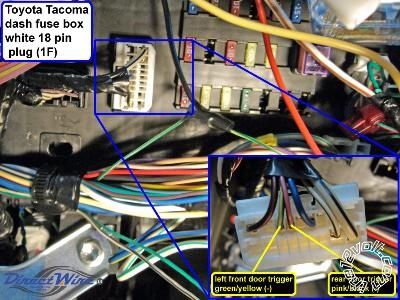
Left Front Door Trigger GREEN/ YELLOW - dash fuse box, white 18 pin plug (1F), pin 7
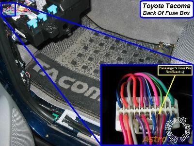
Right Front Door Trigger RED / black - dash fuse box, rear, white 22 pin plug (1I), pin 8
Left Rear Door Trigger pink/black - dash fuse box, white 18 pin plug (1F), pin 6
Right Rear Door Trigger same as left rear door trigger
Remote Start, Security, Keyless Entry, Accessories (Continued)
Item Wire Color Polarity Wire Location
Dome Supervision blue - dash fuse box, black 13 pin plug (1E), pin 9
Trunk/Hatch Pin N/A
Rear Glass Pin N/A
Hood Pin N/A
Trunk/Hatch Release N/A
Trunk Release Motor N/A
Fuel Door Release N/A
Power Sliding Door (Left) N/A
Power Sliding Door (Right) N/A
Factory Alarm Arm purple (driver door key lock) - driver kick, gray 10 pin plug, pin 4
Factory Alarm Disarm GREEN/ black (driver door key unlock) double - driver kick, gray 10 pin plug, pin 8
Disarm No Unlock use keysense
Trunk Alarm Shunt N/A
Tachometer BLACK/ white ac data link connector, white 16 pin plug, pin 9
Wait to Start N/A
Neutral Safety N/A
Clutch Pedal BLACK / YELLOW + clutch switch, black 2 pin plug, pin 2
Fuel Pump BLACK/ red + driver kick, white 18 pin plug, pin 8
Rear Defroster N/A
Mirror Defroster N/A
Left Front Heated Seat purple + resistor driver kick, white 18 pin plug, pin 4
Right Front Heated Seat purple + resistor passenger kick, gray 11 pin plug, pin 2
Speed Sense PURPLE / white ac dr kick junc box, wh 20 pin plg, pin 10, or radio, wh 28 pin plg, pin 17
Brake Wire blue + dash fuse box, white 13 pin plug (1D), pin 13
Parking Brake GREEN/ YELLOW - dash fuse box, white 18 pin plug (1C), pin 5
Horn Trigger GREEN/ red - dash fuse box, white 18 pin plug (1C), pin 10
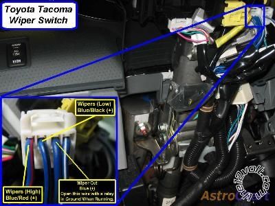
Wipers blue/black (low), blue/red (high), blue (ignition) + wiper switch, white 10 pin plug, pins 3, 4, and 2
Left Front Window (Up/Down) blue - blue/black A power window master switch, white 18 pin plug, pins 10 - 12, or 3 - 4
Right Front Window (Up/Down) blue / YELLOW - black A driver kick, white 12 pin plug, pins 2 and 3
Left Rear Window (Up/Down) GREEN / WHITE - GREEN/ red A driver kick, white 7 pin plug, pins 6 and 5
Right Rear Window (Up/Down) GREEN/ black - green A driver kick, black 8 pin plug, pins 7 and 3


 ------------- Gary Sather
Posted By: joeschmuck
Date Posted: July 28, 2013 at 9:51 AM
@tonanzith
Do you have higher quality pictures, the ones posted are difficult to read (letters are all blocky). These are really nice to have for certain!
Posted By: joeschmuck
Date Posted: August 03, 2013 at 10:33 AM
Deleted.
Posted By: tarline
Date Posted: November 10, 2013 at 9:54 AM
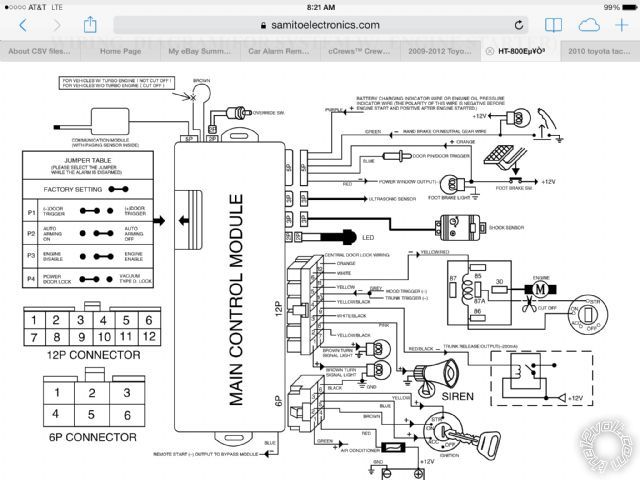
Hello, I'm also new and I'm really glad to find so much info. I'm installing a Samito Electronics HT800 with an Optimax PKALL data module (Bypass)in my 2012 tacoma crew auto, 4x4, . I've run into a few wiring snags, many that have been solved with the pictorials shown. The text on the pics is really hard to read, so any help there would be appreciated. On the PKALL it shows the two wires going to the ECM as "data 1 and data 2" not as txt or rxt. is there a difference? There is one other wire that should be connected to "(-) while running". I have no idea where that should be.
On the alarm/remote start there is one wire that says to connect to oil pressure or ammeter. I can only guess that is to show the remote start that the engine is running. Most of the forums show a connection to the tach. Is that the same? I'm only over my head by a little bit. If I can solve the above, I think I'm home free..
Thanks for any and all help
Posted By: joeschmuck
Date Posted: November 10, 2013 at 1:55 PM
For the PKALL, the PURPLE / White wire is the RX (Data In) and connects to the pink/green (RX) line. The Yellow/Black TX (Data Out) connects to the lt. GREEN/ red (TX) line.
The Blue/White (-) While Running line will connect to a (-) Status Output line from your alarm/starter electronics. I do not have the manual for your selected model so I cannot tell you which pin it would be.
When I installed my Python remote, I used about a third of the wires and removed the rest from the connectors as they were not needed for my installation. I did however save those wires in case I need to use one in the future. I did the same to the PKALL. It just cleaned up the installation.
Welcome to the forums and good luck.
Posted By: tarline
Date Posted: November 11, 2013 at 7:13 AM

Maybe this diagram will help..
Thanks
Posted By: tarline
Date Posted: November 11, 2013 at 7:22 AM
Trying to make it more readable
Posted By: tarline
Date Posted: November 11, 2013 at 7:23 AM
BTW.. Thanks for the info Joeschmuck
Posted By: joeschmuck
Date Posted: November 11, 2013 at 3:06 PM
tarline wrote:
BTW.. Thanks for the info Joeschmuck
I hope it helped. Those diagrams are not very good, as you are aware of. If you are still looking for answers, if you can post a link to the location of the installation manual, assuming it's available online, that would help.
Posted By: tarline
Date Posted: November 11, 2013 at 3:31 PM
www.samitoelectronics.com/royalguard/HT-800E.pdf
Thanks for all the help
Posted By: joeschmuck
Date Posted: November 12, 2013 at 4:43 AM
tarline wrote:
www.samitoelectronics.com/royalguard/HT-800E.pdf
Thanks for all the help
So it looks like you would connect the PKALL Blue/White (-) While Running line to the BLUE wire coming out of the 800 Control module (bottom wire on page 22).
I'm not sure what to do about the engine run wire. You could try to connect it to the tach line and see if it works. Basically it is saying the line must be 0 VDC before the car is running and then +12 VDC when it is running. If you run into a hardship with this line, you could just try to tie it to +12 VDC to see if that works. I'm sure this line is to keep the remote starter from attempting to start the car when it's already running. You could test out the Tach pin with a volt meter to see what it reads while the truck is Ignition Switch On, and Engine Running. See if it does qualify.
Posted By: tarline
Date Posted: November 12, 2013 at 2:31 PM
Thanks for all the help,
I will get to work on this on Saturday morning
Tom
Posted By: joeschmuck
Date Posted: November 12, 2013 at 2:58 PM
If you're not use to being in confined spaces like under the dash, just take your time. It took me several days to install my system but I took my time, figured out where the modules would fit once I closed up the console and dressed up the wiring where it looked nice a neat. IF you haven't done it before, it's actually a challenge. You may think there is a lot of room under the dash but start to factor in parts that move and how hard it is to reach some of the empty locations, yea, a few days is not unreasonable. My first day was locating a spot for everything, hooking in the PKALL, and then making almost all the remote starter connections. The second day I routed the hook pin switch, door lock/unlock wires and horn. Then I programmed the modules and tested it. Lastly I corrected me errors for the door lock/unlock signal.
If you can write down on a piece of paper a listing of all the wires you need to connect and where they all go, then you have the hardest part done.
Good Luck!
Posted By: tarline
Date Posted: November 15, 2013 at 9:03 AM
One more question.... Remote is half wired with no power on. When I unplugged the lower panel with the mirror, RSC, etc. when I plugged them back in I have a constant "Trac Off" and "check engine" lights on that won't clear. Consequently the Trans won't shift correctly and slows to a crawl on an uphill grade. I suspect something in the ignition connection for ck engine, but reconnecting the kick panel switches won't clear the TracOff signal that I'm pretty sure is tricking the transmission..
Any thoughts? Thanks
Posted By: joeschmuck
Date Posted: November 15, 2013 at 9:38 PM
tarline wrote:
One more question.... Remote is half wired with no power on. When I unplugged the lower panel with the mirror, RSC, etc. when I plugged them back in I have a constant "Trac Off" and "check engine" lights on that won't clear. Consequently the Trans won't shift correctly and slows to a crawl on an uphill grade. I suspect something in the ignition connection for ck engine, but reconnecting the kick panel switches won't clear the TracOff signal that I'm pretty sure is tricking the transmission..
Any thoughts? Thanks
Did you disconnect any other electrical connection on the fuse block? I know I had to so I could move the fuse block around. Also do you have an OBD2 scanner? You may be able to use it to reset any alarm condition that no longer actually exists.
Also are you sure you connected the remote starter wires properly? How did you connect the wires, tell us exactly how it was done.
And did you write out on paper which connection go to which wires before you started? You might want to state what you did if you expect to get educated answers.
Posted By: tacoma13
Date Posted: February 26, 2014 at 10:31 PM
Can someone help my confusion and ignorance.I have 2013 tacoma 4 doors w/viper 5704 & pkall would I need to use diodes like this setup?I've seen other setups that didnt mention anything about diodes so Im lost?
-------------
VP74
Posted By: joeschmuck
Date Posted: February 27, 2014 at 4:18 AM
tacoma13 wrote:
Can someone help my confusion and ignorance.I have 2013 tacoma 4 doors w/viper 5704 & pkall would I need to use diodes like this setup?I've seen other setups that didnt mention anything about diodes so Im lost?
You are not being very specific, diodes where? If you use a relay then there must be a diode across the coil, in the proper direction. Some coils have a built in diode, some do not. That is the only place I installed any diodes for my installation.
Posted By: dooododoo
Date Posted: April 25, 2015 at 8:06 PM
I am looking for a factory fob 3X lock press remote start option. Will Tacoma 2015 start if I install only an EVO-ALL?
-------------
Toy Taco
Posted By: iccor56
Date Posted: December 20, 2016 at 4:58 PM
i am trying to wire up my 2008 tacoma and can not for the life of me find the connector with Tx and Rx.
can anyone point me in the right direction to find that connector?
Posted By: joeschmuck
Date Posted: December 20, 2016 at 6:25 PM
iccor56 wrote:
i am trying to wire up my 2008 tacoma and can not for the life of me find the connector with Tx and Rx.
can anyone point me in the right direction to find that connector?
Did you look and read the first page of the thread? The connector plugs into the ignition switch, assuming that your 2008 has similar wiring.
BTW, it took me several days of planning and taking a lot of things apart before I could wire in my Python remote but it was well worth the effort. The overall effort was several days and that is just because I wanted the installation to look professional.
Posted By: iccor56
Date Posted: December 20, 2016 at 8:53 PM
that is the first place i looked. no plug fits the the shown image, the install description or has unidentified use.
the main ignition plugs are a big double decker 12 gauge wire plug and a double decker small wire plug with like 20 connections.
Posted By: joeschmuck
Date Posted: December 21, 2016 at 7:17 AM
Unfortunately I don't think I'll be of much help. It's honestly been quite a while since I've taken my truck apart.
What engine bypass unit are you using? Have you checked their site to ensure you have the proper wiring diagrams for it? Also do they offer a support line so they can explain where to connect it? It could be in that small wire connector you mentioned but the immobilizer device should give you detailed instructions on where to connect it to, unless you are in my shoes and bought something that was intended for a professional installation and they give you no instructions.
Lastly, I looked up the wiring diagrams for a 2006 Tacoma (because that is part of what I used) and it's the same as the 2009 (which I have). So I'm not sure why you can locate the wires. Take more apart!
Here is a link to the ECU wiring diagram
https://www.customtacos.com/tech.old/files/05FSM/data/ileaf/06toyewd/06toypdf/ewd/2006/tacoma/h/em01d5.pdf
Sorry, I don't mean to sound condescending or anything. Look harder, remove the ignition switch completely to ensure you didn't miss some hidden wires, and check the immobilizer company for help.
Good Luck!
|