2012 Kia Sorento Alarm/Remote Start Pictorial
Printed From: the12volt.com
Forum Name: Car Security and Convenience - Alarm/Remote Start Pictorials
Forum Discription: Installer submitted Alarm, Keyless Entry, and Remote Start Pictorials from our Car Security and Convenience forum.
URL: https://www.the12volt.com/installbay/forum_posts.asp?tid=130048
Printed Date: May 01, 2026 at 7:52 PM
Topic: 2012 Kia Sorento Alarm/Remote Start Pictorial
Posted By: chev104275
Subject: 2012 Kia Sorento Alarm/Remote Start Pictorial
Date Posted: January 04, 2012 at 8:08 PM
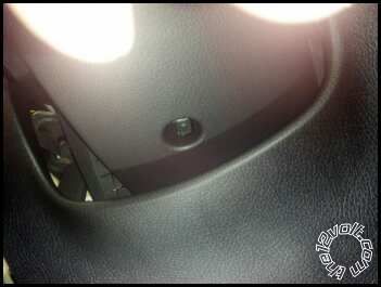
Figured i would give this a try pics are kind of fuzzy (taken with my phone)
This is on a 2012 kia Sorento Regular key Using a 4103
2 phillps head screws in bottom corners
white clips on back side of dash panel very easy to break cheap plastic
more cheap clips
2 phlips head screws in side of front panel
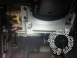
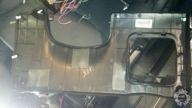
5 10mm bolts and 1 10mm nut holds this in
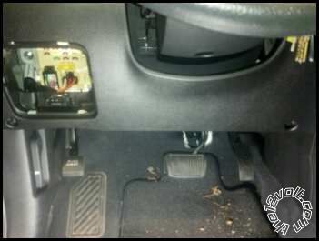
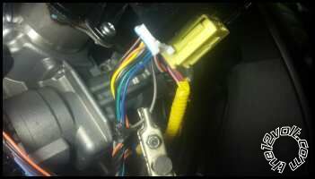
Brake-yellow wire at switch
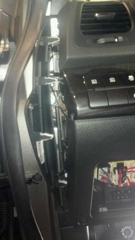
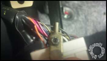
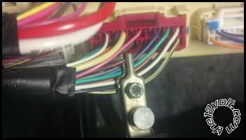
Drivers door unlock-Back of fuse box (3 10mm bolts hold fuse box in) middle plug yellow/black test using the key in the drivers door turning the key 2 times will ground this wire. Need to use this wire tied in with the unlock wire using a diode between to isolate the 2 or drivers door wont unlock (Diode band faces remote start)
Unlock-Gray/Black ground triggered bottom connector right side of fuse box
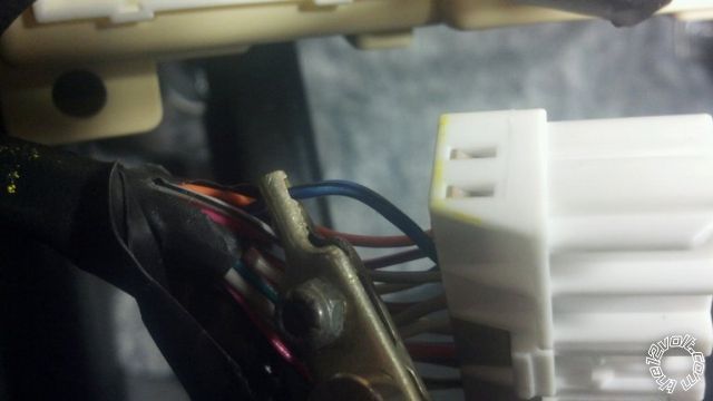
Lock-Blue/Black ground triggered same connector as unlock
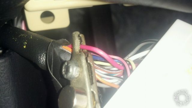
Factory alarm disarm-pink same connector as locks test using key in door
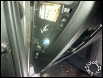
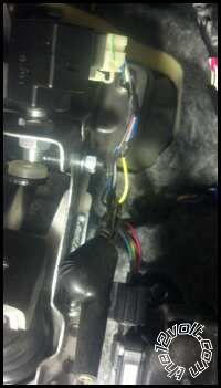
Hood trigger-RED / black in red connector front of fuse box when the hood is open wire is grounded (You can kind of see the white connector to the left of the red connector that has the locks in it)
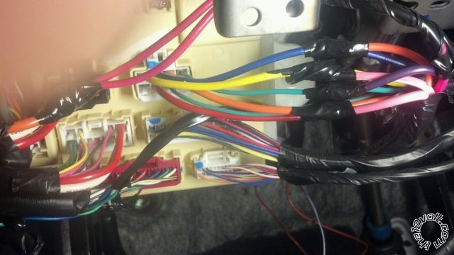
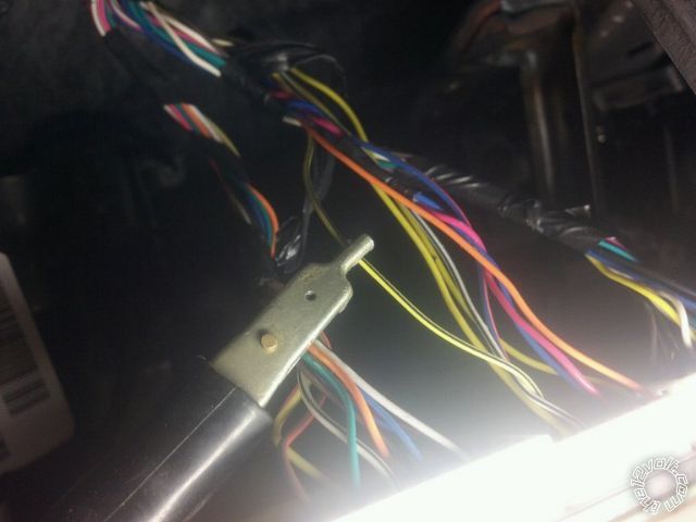
fuse box orange is ing 1,blue acc1,yellow is acc2,green is starter
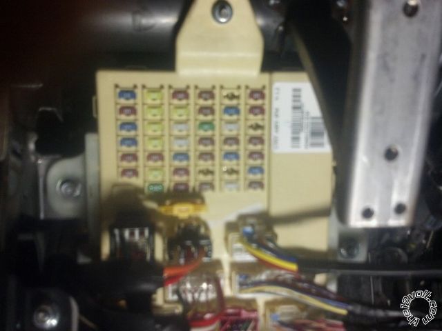
lrg black connector in middle orange is 12v
Horn-Gray/black negitive
tach- yellow wire cylinder 4 coil
[2 I forgot to add]
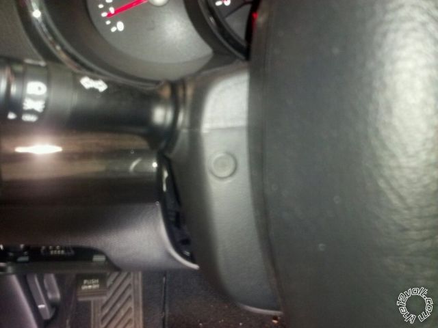
2 Phillps head screws one on each side
1 Phillps head under column shroud ------------- If i Can't Install it I Don't need it Joe
Replies:
Posted By: shortcircuit161
Date Posted: January 06, 2012 at 11:20 AM
Thanks for the pictorial. I did a 2011 Sorento last year with smartkey. Real nice vehicle to install in.
Posted By: chev104275
Date Posted: January 06, 2012 at 6:24 PM
Yea not bad at all I do alot of them
-------------
If i Can't Install it I Don't need it Joe
Posted By: chev104275
Date Posted: October 04, 2012 at 4:45 AM
Just an update the 2013 is the same truck for both the reg key and smart key
-------------
If i Can't Install it I Don't need it Joe
Posted By: bpracin13
Date Posted: January 10, 2013 at 5:59 PM
Had a quick question on what type of diode your using on this install puttin my first one in this weekend and was wondering thanks
Posted By: chev104275
Date Posted: January 10, 2013 at 6:54 PM
I used a 1n4007
-------------
If i Can't Install it I Don't need it Joe
Posted By: voltswagon
Date Posted: December 20, 2013 at 10:42 PM
I'm thinking of getting 2013 Sorento. Xpresskit does not have anything listed for stand key. So we dont need any bypass for these vehicles?
-------------
Dont Drive and Text, but
Do Text Then Drive
Posted By: chev104275
Date Posted: December 21, 2013 at 4:28 AM
If it's us built then no transponder. All the wiring is the same as the 12
-------------
If i Can't Install it I Don't need it Joe
Posted By: mandofever
Date Posted: December 30, 2013 at 3:36 PM
Apologies for a partial repeat question here, i just made a similar post on another thread about this before i ran across your pictorial.
You mention that the lock/unlock is ground triggered but all the wiring diagrams i've found for this vehicle show the door lock/unlock and arm/disarm wires as negative which i assume means they require positive pulse to trigger. Am I misunderstanding this?
The same question applies to the dome light and horn and trunk release which are also listed as negative on all wiring diagrams... Do these all require relays to reverse polarity and pulse positive?
Also the diagrams show the parking lights having a negative wire at the switch harness as well as two separate (L & R) positive wires at the dash fuse box. which of these should be used?
Posted By: chev104275
Date Posted: December 30, 2013 at 7:05 PM
All the wiring labeled negative trigger requires a ground to activate the circuit.
For parking lights use the blue at the switch ground triggered. You can also grab parking lights in the back of the fuse box same blue wire.
Make sure you test each wire with a dmm before you connect to it to avoid any expensive damage to your truck.
-------------
If i Can't Install it I Don't need it Joe
Posted By: mandofever
Date Posted: December 31, 2013 at 9:49 AM
Thanks for the quick reply and for the clarification, your input is invaluable. I've been researching for days and no diagram seems to mention that the (-) indicates negative trigger, i assumed it meant that the wire would test negative at rest with the DMM and require a positive trigger.
For the arm - disarm - lock - unlock - parking lights - horn - and dome light controls, my compustar RS/Alarm provides 250mA negative outputs. Are these durable and safe enough to connect directly to vehicle functions as triggers, or should i add relays to provide stronger ground triggers and protect the RS head unit?
Also, I plan to connect the driver door unlock to the 2nd unlock output on the RS unit for driver door priority unlock. would this still require the use of the diode to isolate? Would i need diode isolation on the other unlock wires?
Lastly, your picture above says the horn wire is negative, but all my diagrams show it with the (-) symbol which you clarified to mean negative pulse. Which is it?
Posted By: mandofever
Date Posted: December 31, 2013 at 9:56 AM
One more thing...
My RS unit has two 12v constant inputs and the car has two 12v constant outputs. Is it bad practice to splice all 4 of those together as i have seen on some so called "professional installation videos". Same goes for the two accessory wires. Can the accessory output from the head be spliced into both of those simultaneously?
Thanks so much for your help :)
Posted By: chev104275
Date Posted: December 31, 2013 at 10:32 AM
I have never done a compustar unit but 250ma should be good for locks,horn and negative parking lights because all your doing is controlling factory relays. I've never done dome light on that truck so you'll have to test that one.
As far as the ingition circuits go they are separate for a reason and should be left that way. So if the system doesn't have enough outputs then you'll have to add relays to make up the difference.
-------------
If i Can't Install it I Don't need it Joe
Posted By: mandofever
Date Posted: December 31, 2013 at 10:49 AM
Thanks so much for your prompt response.
I am unsure what to test for on the dome light circuit. Do i need to test amperage required to trigger to determine if a relay is needed?
Posted By: chev104275
Date Posted: December 31, 2013 at 10:55 AM
DOMELIGHT SUPERVISION BROWN (-) @ LEFT FRONT A Pillar, (WHITE, 22-PIN PLUG), PIN 1
Check the amp draw see if it's under the 250ma
I would get the basic system working then start adding things like dome light
As far as the drivers door priority you should be able to use the yellow/black in the back of the first box to unlock just the drivers door and use the gray/black unlock wire for the rest of the doors.
-------------
If i Can't Install it I Don't need it Joe
Posted By: mandofever
Date Posted: December 31, 2013 at 11:08 AM
Awesome, Thanks so much!
Posted By: mandofever
Date Posted: January 06, 2014 at 9:34 AM
Everything went great on this install, including the drivers priority unlock! Thanks so much for your guidance. One last question though...
My wiring diagram only called for connecting the driver door pin which obviously leaves the other doors unprotected. When I go back and connect the other doors pins do i need to diode isolate them all separately? Diode bands facing away from remote start unit?
Thanks for your help
Posted By: chev104275
Date Posted: January 06, 2014 at 9:43 AM
What did you end up using for door trigger Door Trigger ?
GREEN/ orange - dash fuse box, white 26 pin plug (FK), pin 10. This should do all doors
-------------
If i Can't Install it I Don't need it Joe
Posted By: mandofever
Date Posted: January 06, 2014 at 10:21 AM
I'm 99.999% sure that's the wire i grabbed. It's listed as drivers door pin on my diagram and it does function properly to trigger the alarm but only on the drivers door. The other doors can be opened without setting off the alarm.
Posted By: mandofever
Date Posted: January 17, 2014 at 12:45 AM
So i got back in there and verified that i did grab GREEN/ orange - dash fuse box, white 26 pin plug (FK), pin 10. I tested and verified that it only goes to ground when the driver door opens, no change in voltage when opening any other door, alarm is not triggered. From there, I tested and then tapped into the 3 other door pins which is where i run into trouble again:
Each door pin wire individually reads between 4-5 volts when closed and goes to ground when it's respective door is opened, as expected. Connecting door trigger input to any individual door works as expected.
Connecting door trigger input to all but drivers door (FR, RL and RR tied together) works as expected. Adding driver door to the mix, with or without isolation (band away from RS) triggers the alarm almost immediately upon arming with all doors closed.
Tried isolating all four doors, alarm triggers with all doors closed
Tried no isolation, alarm triggers with all doors closed
Isolating driver door only, alarm triggers with all doors closed
Isolating all but driver door, alarm triggers with all doors closed
Thoughts? Am i missing something obvious?
Thanks in advance for any assistance you can provide.
Posted By: mandofever
Date Posted: January 20, 2014 at 12:02 PM
FOLLOW UP: I couldn't find a solution to the door pin problem so i grabbed the dome light wire (Brown -) driver "A" pillar, white 22 pin, pin 1. Worked perfectly! Just don't forget to disconnect the battery and give it time to discharge (i waited 30 mins) before pulling pillar trim so you don't risk tripping an airbag.
Posted By: empyrials
Date Posted: December 04, 2015 at 8:39 AM
I love this guide, however i wish i would of found it before i got the idatalink module lol.
However that being said, i got my remote start working with the Viper 5706v and door locks workings while the car is running. However when i use the factory Keyfob or use the key to unlock the door(which disables the factory alarm) it doesn't disable the Viper Alarm... Why? what are possible things i can check for this? I flashed the iDatalink with the firmware option to disable the viper alarm when the factory alarm is disabled.
Posted By: scprez
Date Posted: January 16, 2016 at 5:25 PM
in doing a 2011 sorento and i have the remote start working great but i cant seem to find the lock and unlock wires. the wires listed here are not there. i also looked at the 2011 kia sorento wiring and it was right either. what i am i missing?
|