Vehicle: 2006 Nissan Sentra SE
Starter: Compustar 6200S
Bypass: N/A
Disassembly:
- Remove coin tray by opening, then pulling up, then out.
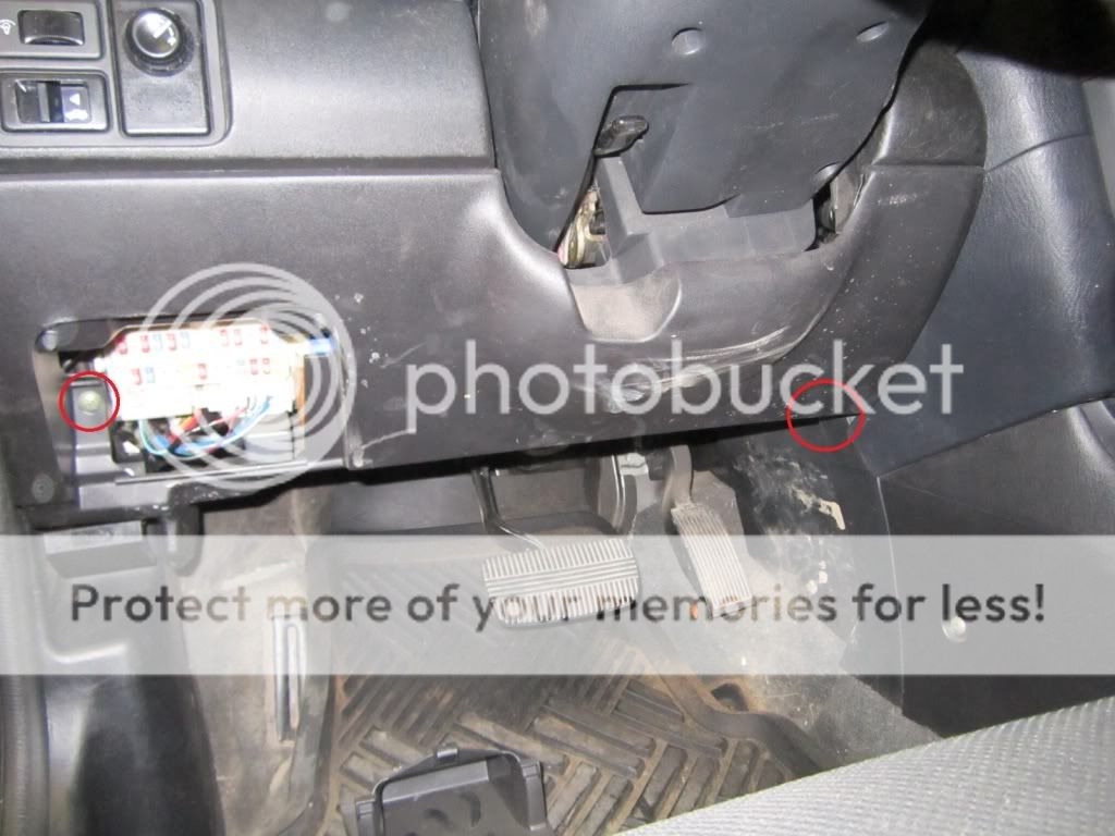
- Remove 2 phillips head screws on knee bolster panel.
- Remove 2 10mm bolts from small metal support bracket. Lift up and out to remove. (No Picture)
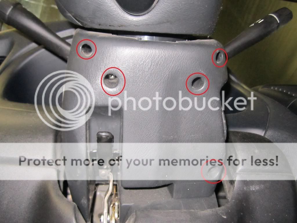
- Remove 5 phillips head screws from lower steering column panel. Pull down to remove.
- Remove door sill plastic. Remove plastic clip holding back of kick panel. Pull rubber weatherstripping back to free kick panel. Pull kick panel towards center of vehicle to remove.
Installation:
- Ignition wires found at ignition switch. Unplug switch and route to right side of steering wheel for more slack or connect further down harness depending on location of main unit and length of wires.

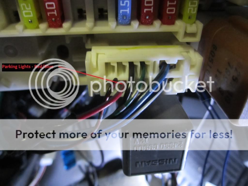
- Parking lights (+) found in plug on lower right of fuse box.
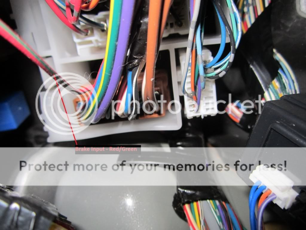
- Brake wire input found in brown plug above driver kick panel (behind fusebox).
- Multiple wires found at SECU to the right of the steering column.

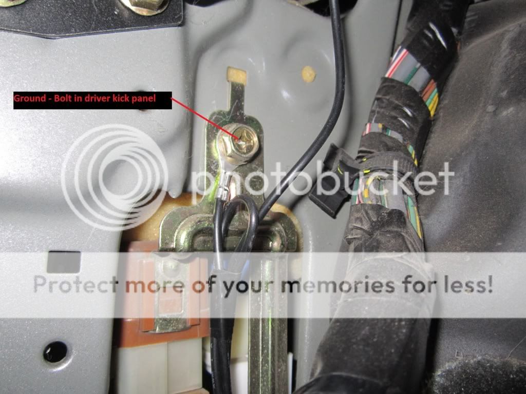
- Ground to factory bolt in driver kick panel. Scrape paint behind metal bracket to ensure good ground.
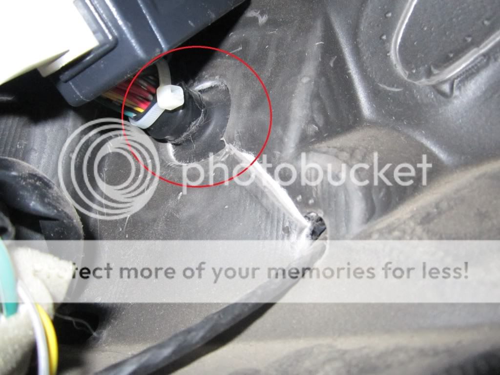
- Access to engine bay through harness boot above driver kick panel.
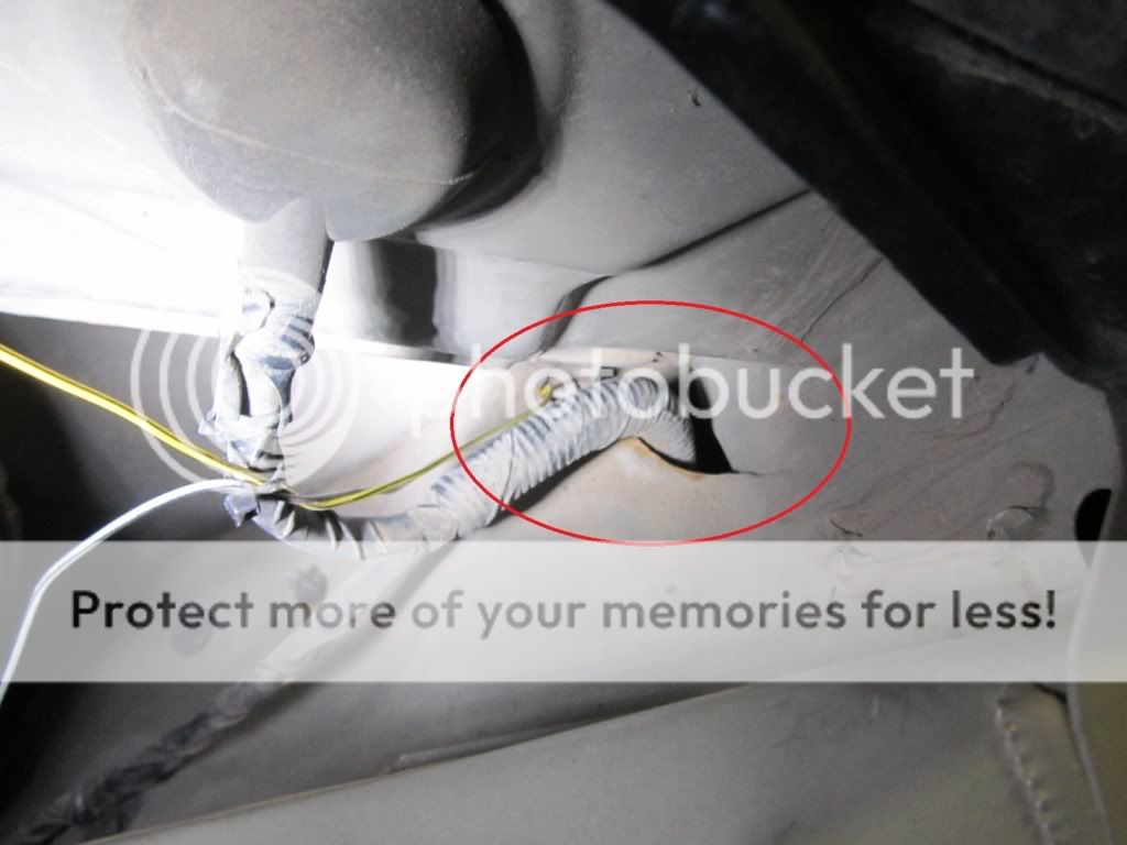
- Wire boot will lead behind inner wheel well and MAY be able to be fished through into the engine bay. Some clips may need to be removed in inner wheel well to reach behind and route through opening and into engine bay. Attach to current wire harness to prevent scraping against metal with vibrations.
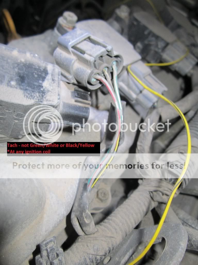
- Tach signal found at any ignition coil.
- Hood pin required aftermarket pin to be added.
-------------
Kenny
Owner / Technician
KKD Garage LLC
Albany, NY 12205
the only thing i would suggest is not using the factory ground connetion and just making your own. Comes in to play more when there is a bypass module used. Can't trust factory ground wires.
-------------
i dont have all the answers and neither do you. Yes im really bad a spelling, i get it.
mikeg74 wrote:
the only thing i would suggest is not using the factory ground connetion and just making your own. Comes in to play more when there is a bypass module used. Can't trust factory ground wires.
I have used several factory ground when using a bypass and never had a issue. Maybe i'm lucky but i find that hard to believe. Maybe I've never had a problem with it because i dont use DEI units lol.
-------------
I drink current, eat ohms, and bleed voltage