2007-2012 Jeep Patriot Remote Start Pictorial
Printed From: the12volt.com
Forum Name: Car Security and Convenience - Alarm/Remote Start Pictorials
Forum Discription: Installer submitted Alarm, Keyless Entry, and Remote Start Pictorials from our Car Security and Convenience forum.
URL: https://www.the12volt.com/installbay/forum_posts.asp?tid=130393
Printed Date: May 15, 2026 at 12:33 AM
Topic: 2007-2012 Jeep Patriot Remote Start Pictorial
Posted By: kreg357
Subject: 2007-2012 Jeep Patriot Remote Start Pictorial
Date Posted: January 26, 2012 at 5:39 PM
2011 Jeep Patriot Pictorial
Basic vehicle with Auto Trans and Power Locks. Remote start with keyless unit install. Used iDatalink
ADS AL CA flashed with ADS AL(DL) CH5 in W2W mode with Ultra Start 1272. The iDatalinlk modules
ADS ALSL CH and ADS DLSL CA2 are the pre-loaded equivalent Solo Series modules for DIYers. Any
quality remote starter can be used with W2W connections.
Disassembly :
Remove the drivers side dash panel with non-marring tools. Four Clips.
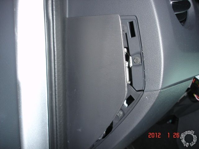
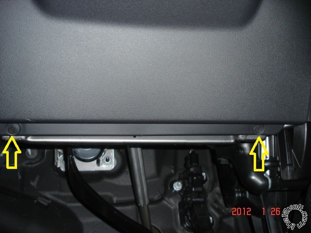
Remove the drivers lower dash panel by removing the two Phillips screws shown at bottom and then pulling
the panel straight away from the dash. There are two clips, one at each top corner.
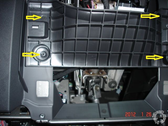
Remove the re-inforced knee plate by removing the four indicated Phillips screws. It is actually two pieces,
the outer plastic and an inner metal plate.
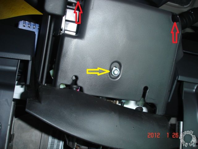
Remove the lower steering column cover by removing the one Torx T-20 screw ( Yellow arrow ) and the two
deeply recessed Phillips screws ( red arrows ).
Remove the drivers kick panel by removing the one fastner at the firewall, raising the front edge of the door
sill cover and pulling the kick panel straight towards the back of the vehicle.
There are only nine wires to connect, three in the kick panel, five at the ignition switch harness and the hood pin.
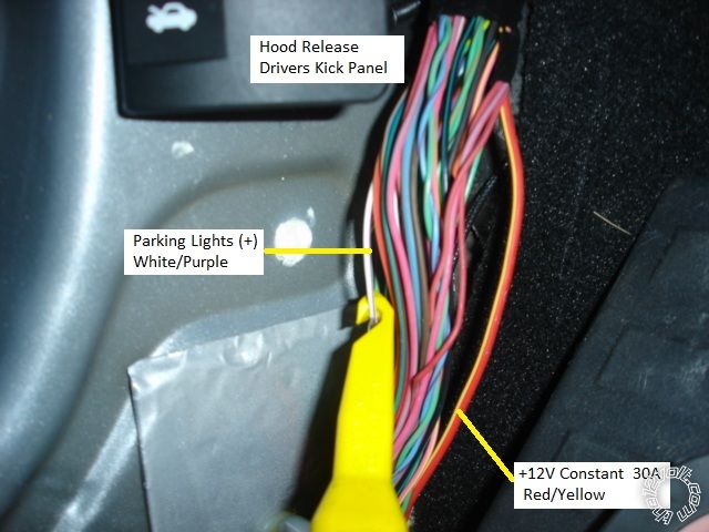
Here is a picture of the kick panel wires. Not shown is a chassis ground connection and the Hood Pin wire. The
+12V constant (RED / Yellow ) feeds the drivers power seat and was safe to use as this vehicle did not have this feature.
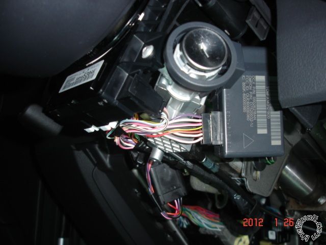
Here is a picture of the right side of the steering column.
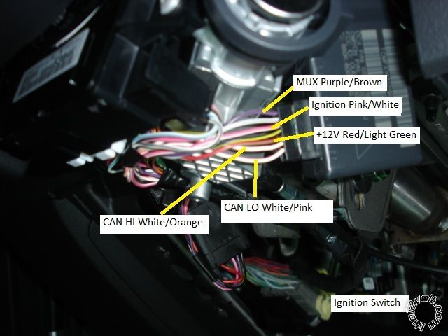
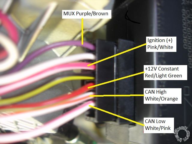
Here is a picture of the ignition wires.
The iDatalink bypass module controls the transponder bypass, locks, alarm and MUX starter control. It also
supplies the remote starter with door & trunk status, E-Brake, Brake Pedal and a Tach signal.
This is only one way of many to add remote start to this vehicle. Total parts cost = $100. Using the ADS HRN CH5
will save a few connections. Using a Fortin EVO-CHR and THAR-CHR2 will cost more but save even more connections. ------------- Soldering is fun!
Replies:
Posted By: kreg357
Date Posted: April 07, 2012 at 2:12 PM
Pictorial Update :
The 2012 Jeep Patriot is the same as prior years. Here is a better picture of the Ignition harness with the necessary
wires identified :
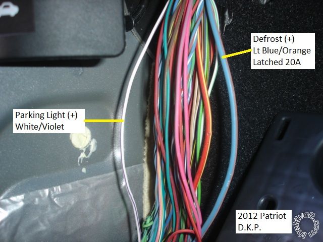
This is a picture of the Defrost wire in the Drivers Kick Panel :
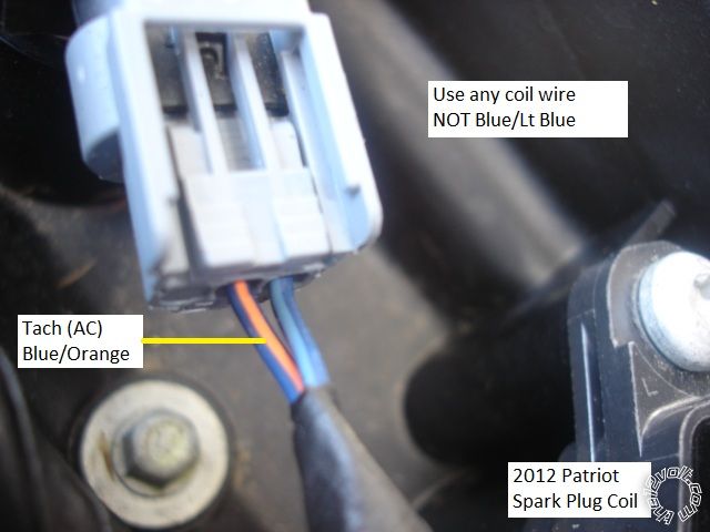
Here is a photo of a spark plug coil for Tach Source ( if necessary ) :
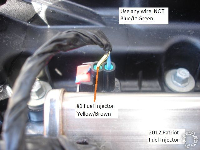
Here is a photo of a Fuel Injector for a Tach source ( if necessary ) :
Finding a engine compartment pass-thru is challenging. There is a large grommet very high up in the Drivers Kick
Panel, above and to the front of the door harness. It exits behind the front quarter panel, forward of the foam insulation
trim. ------------- Soldering is fun!
Posted By: danieljames
Date Posted: December 18, 2013 at 8:06 AM
What watt ohm resistor do I use for the accessory wire to the MUX wire and the second starter to the MUX I'm installing viper 5701
-------------
DJDoo
Posted By: kreg357
Date Posted: December 18, 2013 at 8:35 AM
What bypass module are you using with the Viper 5701? Most of the current offerings from iDatalink, Fortin and XpressKit handle the MUX wire directly with no need for relays or resistors. This install used an iDatalink bypass module and only required seven wire connections to the vehicle. A key was used to program the bypass module to the Jeep but no key was hidden / left in the vehicle.
-------------
Soldering is fun!
Posted By: danieljames
Date Posted: December 18, 2013 at 8:46 AM
A universal one where the chipped key must be installed in it I've found that it takes a 560 ohm resistor for the accessory to MUX And a 180 ohm for second starter but nothing says what watt to use any help I am greatful for thanks
-------------
DJDoo
Posted By: kreg357
Date Posted: December 18, 2013 at 9:34 AM
Here is a link to DirectFax TechDoc #1084. If you have the correct resistor values you can use the wiring shown in this
document to handle the MUX wire. https://www.the12volt.com/installbay/file.asp?ID=517
You will also need some more relays and resistors ( or a DEI 5451M module ) to handle the power locks. It's definitely
a bit more works to do it without a full featured bypass module. ------------- Soldering is fun!
Posted By: danieljames
Date Posted: December 18, 2013 at 9:53 AM
Thank you very much yeah the vehicle doesn't have power locks that's why I went for the cheaper universal bypass module my dumb mistake. Just to make sure the resistor is to be grounded at one end and to the relay also sorry but do I need to hook the key side of the MUX wire to the second starter relay 87a thanks so very much for ur time
-------------
DJDoo
Posted By: kreg357
Date Posted: December 18, 2013 at 10:22 AM
Correct, one side of the resistor is to chassis ground and the other is to Pin 87 of the relay. No, the Starter Relay has no connection on Pin 87a, it's Pin 30 output get directly connected to the ( then un-interrupted ) vehicle side of the PURPLE / Brown MUX wire. Follow that wiring diagram using the thin (-) 200mA Starter and Accessory outputs from the Viper as the relay Pin 85 inputs. Hopefully your Patriot does not have the Factory Alarm system.
-------------
Soldering is fun!
Posted By: danieljames
Date Posted: December 18, 2013 at 5:33 PM
Ok this is the wire diagram I'm going off of
Battery Constant 12v+ Positive Wire (+): RED / Orange
Battery Constant 12v+ Positive Wire Location: Ignition Switch Harness
Starter Positive Wire (+): Yellow/Gray
Starter Positive Wire Location: Ignition Switch Harness
Second Starter Positive Wire (+): Violet/Brown
Second Starter Positive Wire Location: Ignition Switch Harness
Ignition Positive Wire (+): Pink/White
Ignition Positive Wire Location: Ignition Switch Harness
Second Ignition Positive Wire (+): N/A
Second Ignition Positive Wire Location: N/A
Third Ignition Positive Wire (+): N/A
Third Ignition Positive Wire Location: N/A
Accessory Positive Wire (+): Violet/Brown
Accessory Positive Wire Location: Ignition Switch Harness
Second Accessory Positive Wire (+): N/A
Second Accessory Positive Wire Location: N/A
Key Sense Wire: Violet/Brown
Key Sense Wire Location: Ignition Switch Harness
Parking Light Negative Wire (-): N/A
Parking Light Negative Wire Location: N/A
Parking Light Positive Wire (+): WHITE/ Violet
Parking Light Positive Wire Location: In Harness in Driver Kick Panel
My last question hopefully is that do I still hook up them as in diagram I'm tearing into the project in the morning so just trying to have all my wires right
-------------
DJDoo
Posted By: danieljames
Date Posted: December 19, 2013 at 12:54 PM
Ok in the middle of this when hooking up the starter 1 from vehicle not for remote start just for starter kill do I use a relay as
Yellow/grey starter 1-pin87
12v+ to -pin86
Green starter input-pin87a
Violet starter output-pin30
GREEN / WHITE alarm arm output-pin85
The factory alarm disarm is going to relay as followed
Alarm.
Light GREEN/ black factory alarm disarm-pin85
12v-pin86
MUX violet/brown-pin30
Ground with 8.5k resistor-pin87
-------------
DJDoo
Posted By: Talent421
Date Posted: December 26, 2013 at 6:32 PM
Kreg357:
I have 1 2012 Patriot that I'm trying to install an
Ultrastart U1280-xr pro with the ADS-ALSL-CH iDatalink Dodge Chrysler Integration Bypass and the iDatalink ADS-HRN-CH5 T Harness Interface Module. Using D2D mode, The Jeep will not start, in fact, it gives no indication that it is even trying to start. I can lock and unlock the doors with the remote start remotes, but when I try to start the car with the remote, I get nothing. You mentioned in this article that used w2w mode and only hooked up 7 wires. While in D2D mode, how many wires should I connect and of course which ones? I have a feeling I'm simply missing a wire connection or two to get this thing to work, but after 2 hours messing with it, I had to call my friend to come and get his car because I couldn't get it to function correctly. Any ideas would be greatly appreciated.
Thanks,
Scott
-------------
Talent421
Posted By: danieljames
Date Posted: December 26, 2013 at 6:54 PM
My system wouldn't start with the neutral safety wire connected to the dball interface I had to ground it and have the neutral safety switch from the alarm in the on position. Also the hood pin switch on the viper was 12v+ at when hood was shut not sure if this help let me know I'll see what else I can think of
-------------
DJDoo
Posted By: danieljames
Date Posted: December 26, 2013 at 7:18 PM
Another quick thought did you set the tach or virtual tach
-------------
DJDoo
Posted By: kreg357
Date Posted: December 26, 2013 at 8:26 PM
Lets start off slowly.
Check the White sticker on the side of the bypass module for the install guide #. Post that so we can be on the same page. ------------- Soldering is fun!
Posted By: Talent421
Date Posted: December 27, 2013 at 8:27 AM
Okay,
on the side of the bypass module the sticker reads as follows:
6FOC55D578
AL64K1.24
2013-03-21
Main question here is while in D2D I only had 12v+ and ground connected on the remote start. Do I need any other wires hooked up?
I also should say that the L.E.D. on the remote start was continually flashing It would not let me enter programming mode so I believe I was in Tach lockout.
-------------
Talent421
Posted By: Talent421
Date Posted: December 27, 2013 at 8:33 AM
Forgot to mention I did have the data cable connected to the R.S. also.
Scott
-------------
Talent421
Posted By: kreg357
Date Posted: December 27, 2013 at 9:26 AM
I don't usually use the Solo series modules. The ADS ALSL CH is a Solo series that can handle most Chrysler products
but I'm not sure if you have to do some type of Platform selection first, prior to making the Installation Mode selection
and then doing the actual vehicle programming. I was hoping that there would be some sort of install guide number
listed that would detail this process. Check for a sticker on the box the module came in.
If you are going D2D, I'm not sure if the Tach signal will work going through the D2D harness. I spoke with Ultra start
Tech Support recently and was told One-Way D2D works but Two-Way D2D was not ready yet. You might have to hard-wire
the Tach signal. Additionally, the Ultra Start will look for a Tach signal the first time the engine is started after install and the
fuses are put back in. If it doesn't see a valid Tach signal, it should switch over to Tachless mode. I believe Tach Mode is the
preferred set-up for your Jeep. The Catch-22 here is the bypass module has to be programmed to the vehicle first so it can
output a Tach signal. Then the vehicle is started with the key and the U1280 learns the Tach signal, then you should be able
to do a successful remote start. The only way to change an U1280 from Tachless Mode back to Tach Mode is by a Factory
Reset process. This will reset all the programming changes made from the defaults, with the exception of the Selectable
Ignition Output ( thick White wire on the 6 Pin harness ). ------------- Soldering is fun!
Posted By: Talent421
Date Posted: December 27, 2013 at 10:24 AM
Kreg357,
Here is the guide I used. I tried searching Idatalinks site with the #'S
I posted above and found nothing.
https://cdncontent2.idatalink.com/corporate/Content/Manuals/DL-CH5/ADS-ALSL-CH5-EN_20130114.pdf
This is for the CAN equipped car. I noticed there was a
"tipstart" model offered, but it didn't reference the 12 Patriot. Is it possible that I have the wrong module?
The more I think about this, the more I realize that I should have connected the ignition wire to the R.S. Possibly need to hardwire the tach signal to an injector which would get me out of "Tach lockout" also.
Scott
-------------
Talent421
Posted By: kreg357
Date Posted: December 27, 2013 at 6:59 PM
First check the ADS ALSL CH box for that white sticker with an Install Guide #. That will help me a bit.
I agree that following the ADS AL(DL) CH5 is the correct final guide to follow. As I mentioned, I don't use the HRN CH5
harness in my installs. I prefer to hard-wire everything. It works better for me and saves some money. According to
the install guide, there are loose wires at Connector F that get connected to certain wires from the U1280. The CH5
harness WHITE/ Red goes to the U1280's thick Blue. Both U1280 thick Red wires go to the RED / White wire. The U1280
Pink Brake wire goes to the Orange wire. And Black to Black for chassis ground.
Did you at any point set the bypass modules Installation Mode to Data Mode ( 1 blink ) and lock it in?
Did the vehicle programming section go exactly as listed in the install guide? Type 3 and 8 are the same.
Think I would plug in the bypass module's ten pin harness and connect the PURPLE / White Tach output wire to the U1280's
Blue/White Tach Input wire. Next perform the U1280 System Reset procedure listed on Page 7. Next just start the Jeep
with the key and watch for the two Parking Light flashes for Tach Learn confirmation. This will happen 30 seconds after
the Jeep is started without a signal on the thick Yellow Starter wire. Then try a remote start. ------------- Soldering is fun!
Posted By: Talent421
Date Posted: December 29, 2013 at 8:08 AM
The only white sticker on the bypass module doesn't show anything that mentions install guide.
I did program the module to the Jeep and it went as planned and yes I locked in the D2D with acceptance. That part went amazingly well.
I'm going to try to get the car back this week and find the error of my ways. ( I'm kinda OCD like that) The wiring differences very well could be the problem. I will post a follow up when I get it right. One way or another I will win this fight.
Thank you for your help so far.
-------------
Talent421
Posted By: kreg357
Date Posted: December 29, 2013 at 4:20 PM
The White sticker with the install guide number might be on the ADS ALSL CH package ( the box it came in with the Flash access hole in the bottom and plastic bag of harnesses ).
Worst case scenario, dump the CH5 harness and go W2W... ------------- Soldering is fun!
Posted By: Talent421
Date Posted: December 30, 2013 at 4:12 PM
I plan on trying 2 more things before I trash the harness and go w2w. Am I going to need relays and resistors to pull that off or will the bypass module handle all that?
-------------
Talent421
Posted By: kreg357
Date Posted: December 30, 2013 at 7:42 PM
If you dump the CH5 harness and go W2W, the only thing extra you will need is a 1N4001 diode. The Type 3 install looks
complicated but the bypass module only has 5 connections to the Jeep. The U1280 remote starter only has 4 wire
connections to the Jeep ( +12V constant power, chassis ground, Parking Lights and the Hood Pin ). Then there are
the wire connections between the U1280 and the bypass module. That's it. You could even go D2D between the modules
and then make the wire connections shown with solid Black and the necessary Red lines.
-------------
Soldering is fun!
Posted By: Talent421
Date Posted: January 01, 2014 at 2:45 PM
Kreg357,
I just wanted to post a follow up to this remote start install.
Finally got it figured out!!!
I really want to thank you for all your help. You made the difference between success and failure and you saved me about $200 in installation charges that Best buy wanted to do this car.
Thanks again.
Scott
-------------
Talent421
|