2002-2007 Trailblazer Remote Start Pictorial
Printed From: the12volt.com
Forum Name: Car Security and Convenience - Alarm/Remote Start Pictorials
Forum Discription: Installer submitted Alarm, Keyless Entry, and Remote Start Pictorials from our Car Security and Convenience forum.
URL: https://www.the12volt.com/installbay/forum_posts.asp?tid=130514
Printed Date: May 12, 2026 at 7:43 PM
Topic: 2002-2007 Trailblazer Remote Start Pictorial
Posted By: kreg357
Subject: 2002-2007 Trailblazer Remote Start Pictorial
Date Posted: February 04, 2012 at 5:53 PM
2005 Trailblazer Remote Start w/Keyless Pictorial
Notes:
2002 - 2007 Trailblazer are the same. This vehicle was a 2005 LT with factory alarm.
Due to the alarm, Passlock2 and door lock system, it is easiest to use a full featured bypass module like the Fortin INT-SL. This
module will handle the Passlock2, locks, factory alarm, parking lights and supply a Tach signal, door pin status & turn on heated
seats / mirrors and defroster if the engine temp is below 32 F.
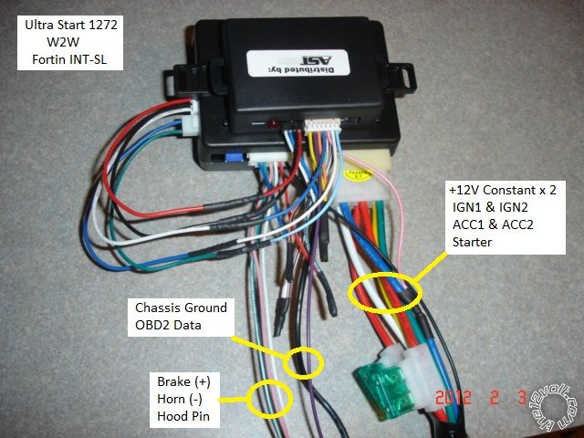
This vehicle has "one touch" starting. As such, there is no need for an Anti-grind circuit.
Below is the R/S and bypass bench prepped in the W2W mode. Only 14 wires to connect to the vehicle including the extra relay
for the ACC2 wire ( not shown ).
Disassembly:
Remove the two Phillips screws at the edge of the under-dash panel. Remove the two Phillips screws retaining the ODB2
connector. Pull the panel down slightly ( clip at center ) and then pull the panel towards the rear of the vehicle. Feed the
OBD2 connector through the hole and release the trailer controller ( if equipped ).
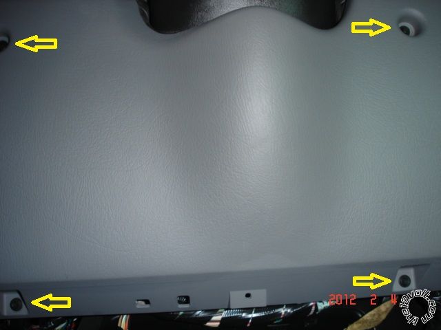
Remove the four Phillips screws retaining the lower dash panel and pull panel staright away at top ( 3 clips ).
Remove the two 10mm bolts retaining the knee plate and remove plate.
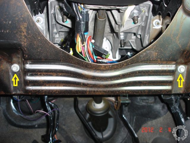
There is no need to open the steering column, all of the necessary wires are now accessable.
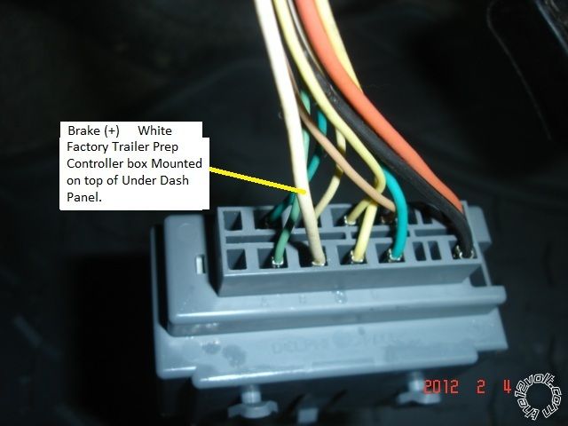
Here is a picture of the Brake wire. Alternate location is at the connector at the top of the brake pedal.
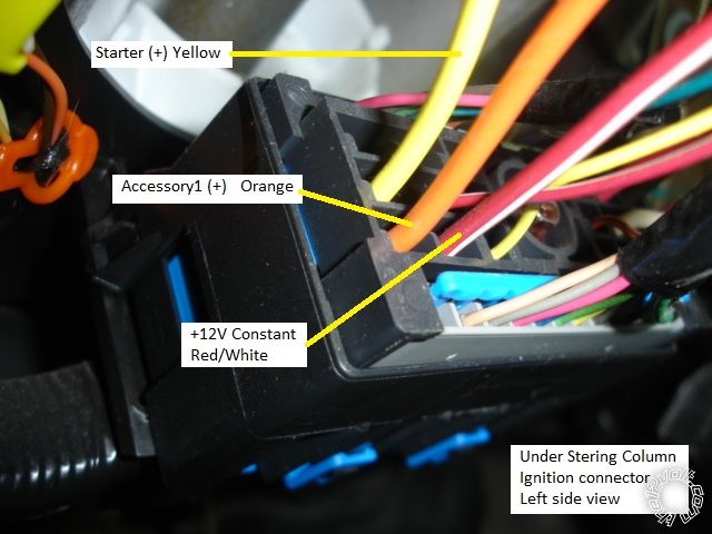
Here is a picture to the under steering column ignition connector, left side.
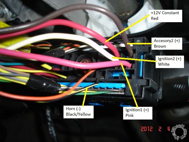
Here is a picture of the under steering column ignition connector, right side.
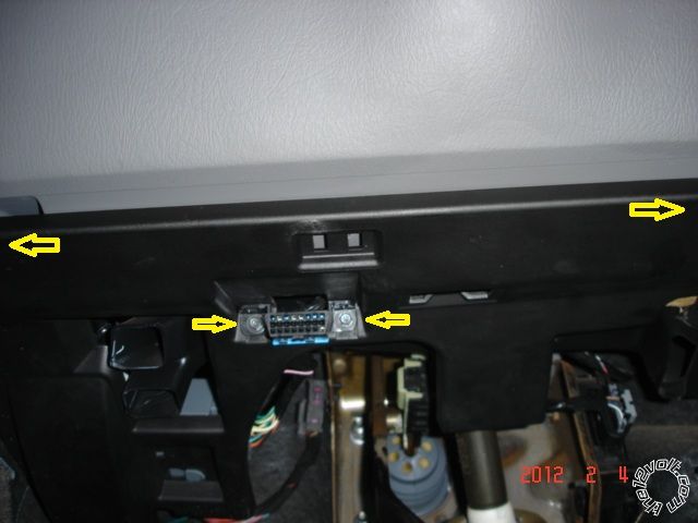
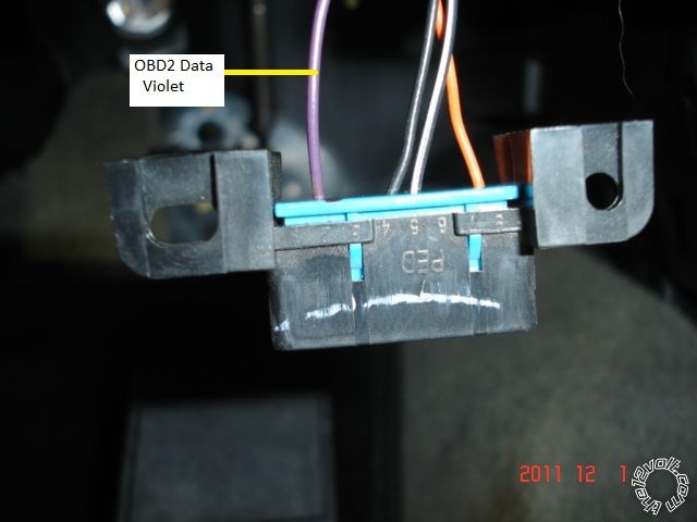
Here is a picture of the OBD2 connector.
Not shown is hood pin wire. Firewall pass-thru is at the large grommet in center area of drivers-under dash that contains the
main engine harness.
------------- Soldering is fun!
Replies:
Posted By: pts760
Date Posted: February 04, 2012 at 8:49 PM
Is the Brown- ACC 2 even necessary on this vehicle? I never hook this circuit up. Sounds like a wasted relay to me.
-------------
I drink current, eat ohms, and bleed voltage
Posted By: howie ll
Date Posted: February 05, 2012 at 2:23 AM
What does the brown control? If only radio and windows you're absolutely right.
-------------
Amateurs assume, don't test and have problems; pros test first. I am not a free install service.
Read the installation manual, do a search here or online for your vehicle wiring before posting.
Posted By: kreg357
Date Posted: February 05, 2012 at 3:55 AM
While I did verify the Brown wire is an Accessory wire, I did not check to see what items were actually supplied with power
by this wire. Powered it up for two reasons. First, it's there and I like to duplicate the regular key functions ( a relay only costs
$2.25 ) and second, this note in the DirectWire info, "Must be powered up. If not, the vehicle will crank as soon as it sees Ignition".
Sorry, I did not check to see if that really happens. While the Starter wire was used, I think GM was in the cross-over period of getting
rid of the Starter wire.
-------------
Soldering is fun!
Posted By: howie ll
Date Posted: February 05, 2012 at 4:00 AM
Kregg, sorry I confused it with a Nissan X-trail. Got to cross the puddle and look at some GM stuff in the flesh!
I should have sussed it out from the single violet data wire, GM system, a Nissan would have had CAN Hi and Lo.
I believe there will be transmission problems and DTCs being thrown if the brown isn't powered up.
-------------
Amateurs assume, don't test and have problems; pros test first. I am not a free install service.
Read the installation manual, do a search here or online for your vehicle wiring before posting.
Posted By: metz35
Date Posted: February 05, 2012 at 7:10 AM
Yes brown needs powered . If not it will crank immediately after seeing ignition.
Posted By: flobee4
Date Posted: February 05, 2012 at 10:22 AM
Actually, it depends on the year of the car. I definitely know that a 02,03,04 does not need the brown 2nd accessory hooked up unless doing a XK01 bypass module with window roll-up. Even then its not the remote start powering it, it's a dedicated output from the XK01 using a relay. I'm not positive when the truck started needing the 2nd accessory... but I'm pretty sure it was 07.
Posted By: pts760
Date Posted: February 05, 2012 at 11:40 PM
kreg357 wrote:
While I did verify the Brown wire is an Accessory wire, I did not check to see what items were actually supplied with power
by this wire. Powered it up for two reasons. First, it's there and I like to duplicate the regular key functions ( a relay only costs
$2.25 ) and second, this note in the DirectWire info, "Must be powered up. If not, the vehicle will crank as soon as it sees Ignition".
Sorry, I did not check to see if that really happens. While the Starter wire was used, I think GM was in the cross-over period of getting
rid of the Starter wire.
Ya a relay may cost $2.25, but for us small retailer's doing 50-100 r/s in this vehicle a year thats saving $112.50-$225 a year on one car. This isn't required just like a lot of GM's around this era ------------- I drink current, eat ohms, and bleed voltage
Posted By: howie ll
Date Posted: February 06, 2012 at 12:48 AM
Cost ALL parts into a job quote as miscellaneous or sundries then make the customer happy if you knock $5-20 off at payment time.
It doesn't stop at relays, think of all the other consumables, I've noticed that solder for instance has quadrupled in price over the last three years, tape, sleeving, wiring, write down of tools, I wouldn't worry too much about $225 on that basis, it pales into insignificance.
-------------
Amateurs assume, don't test and have problems; pros test first. I am not a free install service.
Read the installation manual, do a search here or online for your vehicle wiring before posting.
Posted By: racerjames76
Date Posted: February 06, 2012 at 8:59 AM
I agree with the OP that we should be duplicating ALL of the key functions whenever possible. I typically do Audiovox units in these and the keyless models don't require any additional parts. I have had to repair way too many GM vehicles that didnt have the Brown ACC wire hooked up, to not do it myself.
When in doubt duplicate everything you can!
Another note, the brake and parking light + wire can be found in the large loom running Drivers side to Passenger side, directly behind and under that large square Ignition connector. Usually it has a silver tape band that says FAP FAP FAP on it. They are usually the largest (besides the Accessory wires) White and Brown wires in that harness.
Also, as most of us know there is another dash version in that vehicle where there may be plastic covers on the very top two 7mm bolts, and a half round metal support that requires four 10mm nuts to be removed.
This is one vehicle where no two techs will use the same location for their hookups. Many different ways to get it done. ------------- To master and control electricity is perfection. *evil laugh*
Posted By: pts760
Date Posted: February 06, 2012 at 11:43 AM
howie ll wrote:
I wouldn't worry too much about $225 on that basis, it pales into insignificance.
I was just pointing out one small piece to the puzzle in the small business world. I'm not gonna nickel and dime a customer for tape, wire loom, solder, diodes, resistors, etc. If they wanna get itemized pricing they'll go to a big box store. I just price r/s a flat rate on easy, medium, and hard. That's one of the reasons my customers keep coming back. My customers like it cause its simple and saves me time from answering unneeded pricing questions. ------------- I drink current, eat ohms, and bleed voltage
Posted By: howie ll
Date Posted: February 06, 2012 at 12:09 PM
Yes but that argument pales into insignificance if you cost in tool write downs and sundries.
-------------
Amateurs assume, don't test and have problems; pros test first. I am not a free install service.
Read the installation manual, do a search here or online for your vehicle wiring before posting.
Posted By: howie ll
Date Posted: February 06, 2012 at 12:14 PM
Apologies, I meant DON'T cost in etc.
Or as a small business, I do know where you're going, I tend to base each job on its profit so maybe our thinking is along the same lines anyway.
A year ago a 528T cost me $7.5, doubled and yes I've checked US trade (wholesale) against UK. The only things cheaper in the US are quality tools and Scotch 33+.
59XX series aren't available here, the 57XXs are and the wholesale price is the same.
-------------
Amateurs assume, don't test and have problems; pros test first. I am not a free install service.
Read the installation manual, do a search here or online for your vehicle wiring before posting.
Posted By: x97chevy
Date Posted: August 30, 2012 at 6:54 PM
Hey can anyone provide clarification on the brown wire ACC2.
I have a Viper 5704 do I just hook this direct to the appropriate wire on the Viper unit or do I need to wire in a relay?? If a relay is required can someone provide guidance please.
Posted By: 91stt
Date Posted: August 30, 2012 at 9:13 PM
Here are the systems the brown accessory 2 wire feeds by years
2002 - 2003
Windshield wiper motor
BCM
Outside moisture sensor
DVD player
2004
Windshield wiper motor
BCM
Outside moisture sensor
2005 - 2006
Windshield wiper motor
BCM
Outside moisture sensor
TCM (5.3L)
2007
Windshield wiper motor
BCM
TCM (5.3L, 6.0L)
I would recommend connecting this wire regardless of year.
-------------
This information is provided only as a reference.
All circuits should be verified with a digital multi-meter prior to making any connections.
Posted By: kreg357
Date Posted: August 30, 2012 at 9:51 PM
For your 5704 Viper, you will be already be using all the H3 leads for IGN1, IGN2, Starter1, and ACC1. You will need to add an external relay for ACC2.
Here is how to wire it up : 30/40 Amp SPDT Bosch style relay
Relay Pin 85 to Viper H2/22 Orange (-) 200mA Accessory Output wire.
Relay Pin 86 and 87 to +12V constant fused at 25 Amps
Relay Pin 30 to truck Brown ACC2 wire.
Relay Pin 87A not used - insulate
-------------
Soldering is fun!
Posted By: x97chevy
Date Posted: September 17, 2012 at 5:14 PM
This was so helpful when doing my install
Posted By: kazp3rr
Date Posted: October 15, 2012 at 10:13 PM
Nice write-up on the R/S...I'm doing a 5704 with xk06 on my 05 tb ls...little confused on some of the connections from the 24 pin harness
any insight or forum links anyone knows of?
I've searched and searched, can't seem to find anything on that~
Getting a bit frustrated with it
Posted By: kreg357
Date Posted: October 16, 2012 at 6:02 AM
While I am not a big user of XPressKit modules, it appears the XK06 w/PLXR firmware only does the Passlock2 bypass. Considering that you are installing a remote start, keyless entry and alarm system ( Viper 5701 ) it would seem to make sense to go with a module like the Fortin INT-SL+.
Making the manual connections to the door locks and door triggers can be a challenge. Here is some some basic help with the H2 connector :
H/1 PNK/WHITE (-) 200mA FLEX RELAY CONTROL OUTPUT Not used
H/2 BLACK/ WHITE (-) NEUTRAL SAFETY INPUT To Chassis Ground ( auto trans only )
H/3 BLUE/WHITE (-) 200mA 2ND STATUS /REAR DEFOGGER OUTPUT Not used ( unless you want to add Rear Defrost )
H/4 GREEN/ BLACK (-) 200mA FACTORY ALARM DISARM OUTPUT Not Used
H/5 RED / WHITE (-) 200mA TRUNK RELEASE OUTPUT Not Used
H/6 GREEN (-) DOOR INPUT
H/7 BLACK / YELLOW (-) 200mA DOME LIGHT OUTPUT
H/8 EMPTY ----------------------------------------
H/9 DARK BLUE (-) 200mA STATUS OUTPUT To XK06 in W2W mode - XK06 Brown wire
H/10 PINK (-) 200mA IGNITION 1 OUTPUT Not Used
H/11 WHITE/ BLACK (-) 200mA AUX 3 OUTPUT Not Used
H/12 VIOLET (+) DOOR INPUT
H/13 WHITE/ VIOLET (-) 200mA AUX 1 OUTPUT Not Used
H/14 VIOLET/BLACK (-) 200mA AUX 2 OUTPUT Not Used
H/15 ORANGE / BLACK (-) 200mA AUX 4 OUTPUT Not Used
H/16 BROWN (+) BRAKE SHUTDOWN INPUT White @ Brake pedal switch
H/17 GRAY (-) HOOD PIN INPUT (NC OR NO) to supplied hood pin
H/18 VIOLET / YELLOW (-) 200mA STARTER OUTPUT Not Used
H/19 BLUE* FACTORY HORN INPUT (Use jumper to set polarity) BLACK / YELLOW to black (-) horn switch or BCM, tan plug, pin E12 H/20 GRAY/BLACK (-) DIESEL WAIT TO START INPUT Not Used
H/21 WHITE/ BLUE ACTIVATION INPUT Not Used
H/22 ORANGE (-) 200mA ACCESSORY OUTPUT Used to control additional relay for Brown ACC2
H/23 VIOLET/WHITE TACHOMETER INPUT white (ac) instrument cluster or PCM/ECM, blue plug
H/24 GREEN / WHITE (-) 200mA FACTORY ALARM ARM OUTPUT Not Used
If you need more help, try making a post in the Car Security and Convenience section with your specific question. There are many forum members that are familiar with Viper and DEI products.
The Viper 5701 is a robust, full featured system designed for DEI trained professionals. The Trailblazer has some non standard wiring that can be difficult for the novice installer. While the pictorial system was not an alarm unit, the Fortin INT-SL+ does supply the door status signals.
Good luck on the install. ------------- Soldering is fun!
Posted By: kazp3rr
Date Posted: October 16, 2012 at 9:33 AM
Thanks for the reply, but I'm seeing a slight diff in the wiring between my supplied 5704 guide, and the schematic you gave?
24 pin connector
H2/1 pink/white (-) 200mA ignition/flex relay control output
H2/2 BLACK/ white (-) neutral safety input
H2/3 blue/white (-) 200mA 2ns status/rear defogger output
H2/4 GREEN/ black (-) 200mA OEM alarm disarm output
H2/5 RED / white (-) trunk release output
H2/6 green (-) door trigger input
H2/7 BLACK / YELLOW(-) 200mA dome supervision output
H2/8 BROWN / black (-) 200mA horn honk output
H2/9 dark blue (-) 200mA status output
H2/10 pink (-) 200mA ignition 1 output
H2/11 WHITE/ black (-) 200mA aux 3 output
H2/12 violet (+) door trigger input
H2/13 WHITE/ violet(-) 200mA aux 1 output
H2/14 violet/black(-) 200mA aux 2 output
H2/15 ORANGE / black(-) 200mA aux 4 output
H2/16 brown (+) brake shutdown input
H2/17 grey (-) hood pin switch
H2/18violet / YELLOW(-) 200mA starter output
H2/19 blue (-) trunk pin/instant trigger input
H2/20 grey/black (-) diesel wait to start input
H2/21 WHITE/ blue (-) remote start/turbo timer activation input
H2/22 orange (200mA accessory output
H2/23violet/white (tach input)
H2/24 GREEN / WHITE (-) 200mA oem alarm arm output
Hopefully you did the same thing I did...one eye still half closed when reading this lol
::fingers crossed:: I'm partial to all those "not used" wires, and for whatever reason, it hadn't crossed my mind that I wouldn't need them.
I don't mind taking the time to do the extra work, and make sure it's right/clean...just want to get her working first.
Thanks again for the help, if you think I need to post in another section after this, I'll be sure to do so~
Chris
Posted By: kreg357
Date Posted: October 16, 2012 at 12:18 PM
Sorry, I used the 24 pin H2 harness from a 4704. Viper has been shuffling around the wires and connectors recently. Usually the color and name remain constant.
-------------
Soldering is fun!
Posted By: kazp3rr
Date Posted: October 16, 2012 at 12:47 PM
no worries, I have the xk06 wired up...car cranks with both the bypass immobilizer and passlock II wired cut and in/out to the bypass module...but I can't seem to get it to program? Hold programming button, crank vehicle, led should flash x3...but no flash? already reset xk06 and tried again
Posted By: kreg357
Date Posted: October 16, 2012 at 6:17 PM
First, did you use the XKLoader cable to flash the XK06 module with the correct PLXR firmware? If not,
is there a sticker on the module with a check mark next to PLXR? Just making sure the module is OK.
In the install guide I have, you should be using the Installation "D" diagram on Page 4. There is no cutting of
any vehicle wires in that install mode. It does show some extra connections for VATs and Passlock1 that aren't
required for your Passlock2 system. The Starter & Ignition connections can be run to the Vipers' H3 wires
( that end up going to those vehicle wires ).
As I mentioned, I'm not a big DEI user and have never used an XK06 for Passlock2. What are you planning for the
door locks? ------------- Soldering is fun!
Posted By: kazp3rr
Date Posted: October 16, 2012 at 10:32 PM
...that's why fresh eyes are always good to have around when it comes to something you've been working on for hours on end...
xk06 preloaded with PGK7...gonna make a run to the audio install shop ((that quoted me $850 for the viper 5704/xk06/install))  HEECCCCCCCCKKKKKKKKKKK no lol hell ebay and a few burn marks from my cheapo soldering iron ::battle scars...one day a story to tell::
so hopefully, after flashing the bypass in the a.m. everything will be working *fingers crossed*
HUGE thanks to Kreg357, you sir are a lifesaver~
btw...what about the door locks? the xk06 handles the front doors and the liftgate through the OBDII wire, right?
::edit::
ok after looking over the install guide for the PLXR firmware, there's no connection to my OBDII wire...that doesn't seem right to me?
Posted By: kreg357
Date Posted: October 17, 2012 at 3:56 AM
As mentioned earlier, the XK06 w/PLXR firmware only handles the Passlock2 engine immobilizer system in your 2005 Trailblazer. It is not the same module as the Fortin INT-SL+, nor does it have the same capabilities / functions. The Trailblazer is easy to do with the correct bypass module, but without a full function bypass module, extremely difficult. Stated more bluntly, the XK06 w/PLXR is not the best module to use on your Trailblazer when installing a remote start, keyless entry, alarm system like the viper 5704. Hence my question about how you were planning to handle the door locks.
Terminology note : A "bypass module" is capable of bypassing the vehicles ignition immobilizer system during a remote start. A "full function bypass module" handles the immobilizer system and other functions. "Other functions" vary by the bypass module and the vehicle. They range from interfacing the door lock system, supplying Door Trigger, Trunk & Hood Status signals, controlling the Factory Alarm and Parking Lights, supplying signals like Tach, Brake and EBrake to even turning on the heated seats. Each manufacturers full function bypass module is different. Different in what it does, different in how it's wired, different in how it is flashed with firmware ( some come pre-loaded from the factory like the INT-SL+).
For the 5704 install, you need to interface the vehicles power door lock system ( keyless entry ) and monitor the door trigger status system ( alarm ). Here is a link to the XPressKit WEB site : https://www.xpresskit.com/VehicleCompatibility.aspx?src=vs1&p=null&year=2005&make=Chevrolet&model=TrailBlazer&ps=1&s=0&c=0 It lists the modules that they have available with the functions supported by each. Once again, while I am not a big DEI user, there are full function modules available from DEI that appear to be similar ( in function ) to the Fortin INT-SL+ module used in the pictorial. Note that the XK06 w/PLXR firmware is in the Transponder Override section, not the Combo section ( Combo is DEI's way of saying Full Function ).
While the $850 price might sound outrageous at first, remember that a quality install shop knows the vehicles, knows which systems and bypass modules are best suited for the vehicle, has the units in stock and can do the install in a few hours. You get your vehicle back the same day with a working system and a lifetime warranty. ------------- Soldering is fun!
Posted By: kazp3rr
Date Posted: October 17, 2012 at 1:05 PM
I think I owe you an apology, Kreg357. I misread what you were saying about the bypass at first. Aftereffects of working a 13 hour shift and coming home trying to get this install done at midnight right afterwards.
I went to the local audio/video install shop and picked up the DBall xpresskit, ($$$ whoaa lol) and the arm/disarm is working...but the locks aren't? neither with my factory fob, or the door panel. any ideas?
it's connected via D2D and the ODBII wire
Posted By: kreg357
Date Posted: October 17, 2012 at 4:11 PM
The DB-ALL can be pricey but it does a lot for you with this vehicle ( if it works ).
OK. DB-ALL flashed with GM1 firmware and going D2D. The install diagram pretty much shows all the necessary connections. Only one from the DB-ALL to the vehicle ( OBD2 )
and the D2D harness between the DB-ALL and the Viper. From the Viper to the vehicle are the two Ignition wires, the two Accessory wires ( one of which would require an extra
relay ), the Starter wire, the Brake input, the Parking Light, the chassis ground connection and the four +12V constant power wires. Not shown is the Neutral Safety wire and
switch.
As for the locks not working, think I would try re-programming the module to the vehicle again. Make sure it follows the guide and responds exactly as shown on Page 4 of the
install guide.
As a last resort, and yes it is a lot of wiring, you could switch over to the W2W install mode and make all the dashed blue wire connections. Also remove the D2D harness as it is not needed in W2W mode. Would look similar to the first photo in the pictorial. ( D2D can be problematic while W2W always works. ) ------------- Soldering is fun!
Posted By: kazp3rr
Date Posted: October 17, 2012 at 5:19 PM
Ok, the past hour has been hectic...I'm at work trying to figure this out while cooking lmao...i go to my car to go to work, turn the key and nada...won't crank, no window action, no lock/unlock action etc etc...the DBall wasn't showing anything from the led, so I went back to the shop and they swapped it for me
I get off pretty late, so I'm gonna get nack at it then...any ideas?
10a fuse for "lock" was blown, but from ehats goin on, I'm assumimg there is a fuse blown somewhere causing my problems?
Posted By: kreg357
Date Posted: October 17, 2012 at 6:22 PM
Properly connected in D2D mode, the Viper / DB-ALL system should have nothing to do with a lock fuse...
Wiring chart for Viper 5704 and DB-ALL w/GM1 ( in D2D mode ) to 2005 Trailblazer
H1/1 RED (+)12VDC CONSTANT INPUT +12v CONSTANT
H1/2 BLACK (-) CHASSIS GROUND CHASSIS GROUND
H1/3 BROWN (+) SIREN OUTPUT SIREN
H1/4 WHITE/ BROWN PARKING LIGHI ISOLATION WIRE NOT USED
H1/5 WHITE PARKING LIGHT OUTPUT *SET VIPER TO (-) gray/black (-) headlight switch or BCM, tan plug, pin E5
H1/6 ORANGE (-) 500mA GROUND WHEN ARMED OUTPUT NOT USED
H2/1 pink/white (-) 200mA ignition/flex relay control output NOT USED
H2/2 BLACK/ white (-) neutral safety input CHASSIS GROUND
H2/3 blue/white (-) 200mA 2ns status/rear defogger output NOT USED
H2/4 GREEN/ black (-) 200mA OEM alarm disarm output NOT USED
H2/5 RED / white (-) trunk release output NOT USED
H2/6 green (-) door trigger input NOT USED
H2/7 BLACK / YELLOW(-) 200mA dome supervision output NOT USED
H2/8 BROWN / black (-) 200mA horn honk output BLACK / YELLOW (-) horn switch or BCM, tan plug, pin E12
H2/9 dark blue (-) 200mA status output NOT USED
H2/10 pink (-) 200mA ignition 1 output NOT USED
H2/11 WHITE/ black (-) 200mA aux 3 output NOT USED
H2/12 violet (+) door trigger input NOT USED
H2/13 WHITE/ violet(-) 200mA aux 1 output NOT USED
H2/14 violet/black(-) 200mA aux 2 output NOT USED
H2/15 ORANGE / black(-) 200mA aux 4 output NOT USED
H2/16 brown (+) brake shutdown input white (+) brake switch
H2/17 grey (-) hood pin switch USE VIPER SUPPLIED HOOD PIN
H2/18 violet / YELLOW(-) 200mA starter output NOT USED
H2/19 blue (-) trunk pin/instant trigger input NOT USED
H2/20 grey/black (-) diesel wait to start input NOT USED
H2/21 WHITE/ blue (-) remote start/turbo timer activation NOT USED
H2/22 orange (200mA accessory output TO EXTRA RELAY PIN 85 *SEE WIRING BELOW
H2/23 violet/white (tach input) NOT USED
H2/24 GREEN / WHITE (-) 200mA oem alarm arm output NOT USED
H3/1 PINK (+) IGNITION 1 INPUT/OUTPUT PINK @ IGNITION SWITCH HARNESS
H3/2 RED / WHITE (87) FLEX RELAY +12V INPUT (30A FUSED) +12V CONSTANT
H3/3 ORANGE (+) ACCESSORY OUTPUT ORANGE @ IGNITION SWITCH HARNESS
H3/4 VIOLET (+) STARTER OUTPUT (CAR SIDE OF THE STARTER KILL) YELLOW @ IGNITION SWITCH HARNESS *cut wire
H3/5 GREEN (+) STARTER INPUT (KEY SIDE OF THE STARTER KILL) YELLOW @ IGNITION SWITCH HARNESS *cut wire
H3/6 RED IGNITION 1 +12V INPUT (30A FUSED) +12V CONSTANT
H3/7 PINK/WHITE (30) FLEX RELAY OUTPUT *Default = IGN2 WHITE @ IGNITION SWITCH HARNESS
H3/8 PINK/BLACK (87a) FLEX RELAY INPUT NOT USED
H3/9 RED / BLACK ACC/STARTER RELAY +12V INPUT (30A FUSED) +12V CONSTANT
H3/10 NC No Connection
Door Lock, 3-pin connector NOT USED
Viper D2D port harness to DB-ALL 4 Pin Data port
DB-ALL 14 Pin Plug Pin2 Violet / YELLOW to OBD2 Violet wire at Pin 2
EXTRA RELAY FOR BROWN ACC2 WIRE
Relay Pin 85 to Viper H2/22 Orange (-) 200mA Accessory Output wire.
Relay Pin 86 and 87 to +12V constant fused at 25 Amps
Relay Pin 30 to truck Brown ACC2 wire.
Relay Pin 87A not used - insulate
All connections should be verified with a Digital Multi Meter.
All connections should be soldered.
After all connections are made, install the Viper's fuses, then program the DB-ALL to the vehicle.
Test the locks. Then start making the necessary programming changes to the Viper. These will include :
Transmission Mode = Automatic
Engine Checking = Tach Mode
and any other features needed / desired
Finally do a Tach Learn and then try a remote start. ------------- Soldering is fun!
Posted By: kazp3rr
Date Posted: October 17, 2012 at 9:32 PM
Sorry, I should have been more clear, neither my windows nor door locks will work from the door panels, my headlights/interior lights won't come on either. I've checked all the fuses, didn't see any that were blown...this project is making me look like I'm so very new to the electronics scene, but I swear this isn't my first rodeo...just been plagued with issues since the beginning.
Posted By: KPierson
Date Posted: October 18, 2012 at 7:14 AM
That $850 for a professional installation probably doesn't seem that bad now. You have to remember when you pay a professional they typically have years of experience and thousands and thousands of dollars of tools to properly diagnose and fix issues that pop up from time to time. More importantly, they also are insured to protect them and your vehicle.
That being said, what were you doing when you blew the fuse? Obviously from the extent of the damage something had to have happened. If you can pinpoint exactly what you were doing at the time you may be able to work backwards from there. Get a vehicle wiring diagram that shows fuses and find the fuse that protects the fuse you blew (if there is one) and check that. It is very possible that this is only a fuse issue. However, it could also be a Body Control Module issue. Checking the proper fuses with an ohm meter is going to be the easiest way to rule out fuses. If it isn't a fuse issue try to find a common connection to all the things that have quit working (ie they are all controlled by the same module, or they all share the same grounding point, etc.).
-------------
Kevin Pierson
Posted By: kazp3rr
Date Posted: October 18, 2012 at 12:07 PM
Ok, here's what I "know" so far lol
megafuse-ok
fuse box connected to bcm is getting power
every fuse that should have constant 12+, does
every fuse that should have power with ign on, does
what works-
brake lights
turn signals
power adjustable seats
horn
dash lights
windshield wipers
gear shift location identifier (name?)
what doesn't work
headlights
park/running lights
interior lights
radio (button lights come one, but nothing else)
power door locks
power windows
sunroof
I hear no clicking from any of the relays anywhere (fuse box under the hood or by the bcm)
Could it be a bcm issue?
I can't help but wonder if there are several independent things going on at once. The security light was on before the no crank/no start issue, if I remember correctly the door locks were working for a short while (I was excited to finally get some results so I can't say for certain) the DBall bypass was programmed to my vehicle at the shop where I bought it yesterday, got home, went through the proper programming steps (led feedback was per the instructions) then after a while I noticed the led indicator on the bypass was no longer coming on. Sorry for leaving this part out yesterday, I was in mini-panic mode while I was posting on here and trying to find a way to get to work.
Thanks guys, I know this is getting to be a headache
and hats off to KPierson for getting back with a reply within hours of the pm...can't thank you enough
Chris
Posted By: howie ll
Date Posted: October 18, 2012 at 1:45 PM
Check (continuity setting with a DMM) all the under hood "big" fuse.
You have multi circuit failings.
Is there power to the lighting feed?
Is there power, constant and ACC to the radio?
-------------
Amateurs assume, don't test and have problems; pros test first. I am not a free install service.
Read the installation manual, do a search here or online for your vehicle wiring before posting.
Posted By: KPierson
Date Posted: October 18, 2012 at 2:14 PM
My advice is to pick one function and troubleshoot it. One of the easier ones listed is the headlights. Get a schematic for the headlights - there should be a switch driving a relay. Determine if the relay is firing. If it isn't, the problem is on the control side, if it is the problem is on the power side. I agree with Howie, there is most likely a "main" fuse somewhere. At least let's hope there is!
-------------
Kevin Pierson
Posted By: kreg357
Date Posted: October 18, 2012 at 3:32 PM
The best way to test a standard fuse is to remove it and do a "static" test with a Digital Multi Meter set to the lowest
resistance scale. Looking for zero ohms.
-------------
Soldering is fun!
Posted By: kazp3rr
Date Posted: October 18, 2012 at 10:18 PM
I'm still at work, but the relay I used for my drl killer isn't getting power (no clicking of the relay) as far as the rest, I'll either check tonight after work, or first thing in the am
Posted By: kazp3rr
Date Posted: October 19, 2012 at 2:14 AM
KPierson wrote:
My advice is to pick one function and troubleshoot it. One of the easier ones listed is the headlights. Get a schematic for the headlights - there should be a switch driving a relay. Determine if the relay is firing. If it isn't, the problem is on the control side, if it is the problem is on the power side. I agree with Howie, there is most likely a "main" fuse somewhere. At least let's hope there is!
and if it isn't?
I'm assuming a bcm replacement would be the other option?
any idea what kind of $ we're talking there?
I called a used parts dealer to see if they had a bcm and how much, but I was otw to work and didn't have the # he needed to verify, calling back in the a.m.
Posted By: howie ll
Date Posted: October 19, 2012 at 2:29 AM
Forget BCM, start testing.
Someone has to be a real klutz to destroy a whole BCM.
-------------
Amateurs assume, don't test and have problems; pros test first. I am not a free install service.
Read the installation manual, do a search here or online for your vehicle wiring before posting.
Posted By: KPierson
Date Posted: October 19, 2012 at 7:09 AM
Howie I've seen it happen. Someone shorted out a non protected (-) output on a Nissan BCM. It actually burnt up all the traces on the ground plane of the circuit board leaving virtually nothing on the board grounded.
As far as it not being a fuse, the next step would be to figure out what all the lost functions have in common. If they are all controlled by the BCM then obviously you would suspect the BCM is damaged. I am honestly not to familiar with GMs and their electrical systems. You'll need a factory manual with wiring diagrams most likely to trace everything back.
In the Nissan/Infiniti world a BCM is around $400. The catch though is since most cars these days have CAN busses the dealership may need to register the new BCM to the car. In many cases simply swapping the part without dealership programming won't work. Again, this is based off my experience with Nissan/Infiniti vehicles.
-------------
Kevin Pierson
Posted By: kreg357
Date Posted: October 19, 2012 at 7:33 AM
Some testing and troubleshooting is definitely in order. Not sure what happened, but it seems that there is an additional relay in the DRL circuit and possibly some cut / re-connected wires where the XK06 w/PKG7 was installed. The reason being, if something is still wired wrong or shorted out, a new BCM will be damaged upon power up. Still hoping that it is only a fuse.
KP is right about going back over everything you did in sequence to help determine what went wrong and when. At the very least, remove the remote starter and restore all wiring back to original condition. ------------- Soldering is fun!
Posted By: kazp3rr
Date Posted: October 19, 2012 at 9:37 AM
Kreg357...already done lol
when the **** hit the fan, that's the first thing I done...every viper component is boxed up in the passengers seat right now, so it's not a r/s wiring issue at this point.
I actually ended up going with the DBall instead of the xk06 after you pointed out the limited features of the xk06 (thanks for that btw)
I'm on the search now for a manual with wiring diagrams...yay me
KP...next time, I'll pay the effin $850 
Posted By: 91stt
Date Posted: October 20, 2012 at 6:20 AM
Here are the wiring diagrams
Doorlocks
Exterior lights
Headlights
Interior lights
Radio
Sunroof
Windows------------- This information is provided only as a reference.
All circuits should be verified with a digital multi-meter prior to making any connections.
Posted By: kazp3rr
Date Posted: October 20, 2012 at 11:28 AM
much appreciated (:
so this morning I had a few min of down time...so I checked
raw batt V +/- 12
@ignition switch
12V constant = +/-12
ignition 1 and 2 = +/- 12
acc 1 and 2 = +/- 12
starter = +/- 12
haven't gotten into the fuse box to test relays yet, my meters probes are a bit too large...safe to use a bit of wire to connect the probes to the ports?
maybe it's my pessimism at work...but it seems like it's starting to look like a bcm issue?
when I picked up my new DMM, I asked the guy how much one was retail, just for doodies&giggles...I guess $195 isn't too bad with a 1-year warranty :)
much less than I was expecting~
Posted By: kazp3rr
Date Posted: October 22, 2012 at 2:19 PM
91stt] wrote:
Here are the wiring diagrams
Doorlocks
Exterior lights
Headlights
Interior lights
Radio
Sunroof
Windows
I can't thank you enough for the diagrams...window is up, I have power to the door lock actuators...but no response from the door panel controls themselves. I'm trying to be optimistic about it being a simple fix, any thoughts?
And for some reason my fine network and the12volt aren't getting along right now, so it's forums via android :P
And again, thanks a ton guys...really saving my arse here
Posted By: vinchinzo
Date Posted: October 23, 2012 at 12:16 PM
Nice job
-------------
When in doubt....kick it!
Posted By: kazp3rr
Date Posted: October 23, 2012 at 12:27 PM
update:
tested all the ignition/crank fuses in the under hood fuse box and they are all reading correctly...I have power to my fuse box beside the bcm, and my door trigger wires are sending signal to the fuse box.
door panels have power/ground to door lock actuators and windows motors, and there is a class 2 data wire signal...but no response from the panel
power to acc/ign/starter wires at the ignition switch, but no crank/start
I checked the splice packs under the RR seat, and getting positive readings from several wires there
could this be some kind of passlock issue? just wondering since the security light is on, and the 30 min relearn isn't working, the light never goes off...
I understand that the passlock system runs through the factory head unit, and the button lights come on the HU, but no display or function of it?
I'm stumped...HELP!
Posted By: KPierson
Date Posted: October 23, 2012 at 2:49 PM
Have you looked at the headlight system yet? Like I said before, pick an "easy" circuit try to fix it.
-------------
Kevin Pierson
Posted By: kreg357
Date Posted: October 23, 2012 at 4:27 PM
Was the XK06 ever connected ( using the PKG7 diagram )? That could have messed with the Passlock2 and be causing the "Security" light issue. If yes, you might want to review which wires were affected and where they go.
-------------
Soldering is fun!
Posted By: kazp3rr
Date Posted: October 24, 2012 at 11:02 AM
kreg357 wrote:
Was the XK06 ever connected ( using the PKG7 diagram )? That could have messed with the Passlock2 and be causing the "Security" light issue. If yes, you might want to review which wires were affected and where they go.
I laid everything out, got rough measurements for the wires, and bench wired the xk06 to the r/s module...but this was before realizing that the xk06 was limited in what it could do. A buddy at the local audio/video install shop hooked me up with a DB-all, which was then connected via ODBII. When the locks/windows etc stopped responding, so did the DB-all, and when I made a trip back to maybe see if it had lost the programming, he swapped it for a new one. Not sure what the deal with it is, didn't say. (forgot about that part guys, sorry...been a hectic past week)
and KPierson I'm heading outside after I finish some things here to start on the headlight circuit, thanks.
Posted By: howie ll
Date Posted: October 24, 2012 at 11:18 AM
I was under the impression that dball or any similar product shouldn't be connected at the OBD 11, they throw false readings on factory/dealer diagnostics. Better to go to the BCM.
-------------
Amateurs assume, don't test and have problems; pros test first. I am not a free install service.
Read the installation manual, do a search here or online for your vehicle wiring before posting.
Posted By: kazp3rr
Date Posted: October 29, 2012 at 1:07 PM
So after cursing myself out for nearly 10 minutes...I think I've got my head back on straight. Turns out, I spent countless hours trying to diagnose the problem, checked the fuse box numerous times (both of them) and somehow, each time I checked them, I missed fuse #31 for the Truck Body Controller...I think livid would be an understatement as to my mindset when I replaced the blown fuse and all my interior lights came on, and truck started right up. Only thing wrong now, is I get no throttle response, Reduced Engine Power light is on...checked the Electronic Throttle Control fuse, don't seem to be any issues with the harness at the throttle body.
sorry for all the hassle over a single fuse...lesson learned though, pen and paper with a checklist is the only way to make 110% sure you checked every single thing.
Posted By: dcmtnbkr
Date Posted: December 21, 2012 at 3:13 PM
Does the bcm need to be powered during r/s? The reason i ask is because i would rather my radio and wipers stay off while the vehicle is warming up, as i dont want to break my wipers if i leave them on and they freeze, and i dont want to wake up the neighbors with my subs. It seems like the best way to make sure they stay off is to not connect the acc2 wire, but obviously i cannot do that if the bcm is required.
Posted By: kreg357
Date Posted: December 22, 2012 at 7:47 AM
Can't hurt to give it a try and leave the Brown ACC2 wire un-powered during a remote start. During post-install testing, you can check to see if the Heat, A/C and fans work properly. Then check to see if the radio and wipers are in-operative. Even better, iIf you have a hand held OBD2 scanner you can verify the absence of codes before and after install to be sure.
-------------
Soldering is fun!
Posted By: dcmtnbkr
Date Posted: December 22, 2012 at 8:24 AM
kreg357 wrote:
Can't hurt to give it a try and leave the Brown ACC2 wire un-powered during a remote start. During post-install testing, you can check to see if the Heat, A/C and fans work properly. Then check to see if the radio and wipers are in-operative. Even better, iIf you have a hand held OBD2 scanner you can verify the absence of codes before and after install to be sure.
Good point, i didnt even think of using my obd2 scanner to check for errors. Thanks for the input.
Posted By: dcmtnbkr
Date Posted: December 24, 2012 at 8:00 AM
Hooked it up without the acc2 connected and it worked like a charm. Radio and wipers stayed off, everything else was running.
Posted By: kreg357
Date Posted: December 24, 2012 at 9:35 AM
That's great! Thanks for the update. What year? Any codes logged? Heat and A/C work OK?
-------------
Soldering is fun!
Posted By: dcmtnbkr
Date Posted: December 24, 2012 at 10:09 AM
2004. I just thought of this, the radio in mine is triggered from the wiper fuse (aftermarket stereo thing specific to this vehicle) So im not sure if the brown acc2 controls the radio or not. Even if it doesn't, i'd still rather not have the wipers turn on. No codes so far, climate control works perfectly.
Posted By: kreg357
Date Posted: December 24, 2012 at 12:14 PM
Good info. Thanks!  ------------- Soldering is fun!
Posted By: lucasoil4u
Date Posted: July 17, 2013 at 3:06 PM
Glad to hear everything worked out as planned!
Posted By: stevieb_wv
Date Posted: December 04, 2014 at 9:36 AM
I hope the OP is still around on this and I know this is an old thread. I have a question regarding this install. I have a very similar setup on a 2002 Trailblazer with 6 high current wires just like the Ultra Start 1272. 2 12V constant, 1 IGN, 1 ACC. 1 Start, and 1 selectable for either Start2, ACC2, or IGN2. According to my manual and the UltraStart manual, these 6 wires are identical.
How are 6 wires being connected to 7 locations as indicated in the picture?
I know that there was some discussion of ACC2 not being needed, and it is set to default to IGN2 but it can't be IGN2 AND ACC2 at the same time.
Posted By: 91stt
Date Posted: December 04, 2014 at 10:36 AM
You will need to use relays to properly add extra ignition or accessory outputs.
I have uploaded a diagram in the downloads section of this site, Adding extra ignitions for remote starting
It shows how to add extra ignitions but the same can be used for accessory outputs by substituting the wire to terminal #86 with the accessory output of the remote start module.
Even though not shown, it is always recommended that the Constant +12V source for terminal #87 be fused. As a personally rule, I do not use any fuse greater than 25A to protect this circuit. Better yet, if you can determine the fuse rating for the ignition or accessory wire you are going to energize, use that as a maximum. Also ensure that the source you are getting the constant +12V can accommodate the additional current. When in doubt, go to the battery for this. ------------- This information is provided only as a reference.
All circuits should be verified with a digital multi-meter prior to making any connections.
Posted By: stevieb_wv
Date Posted: December 04, 2014 at 10:49 AM
From looking at your schematic and reading your post, basically, you are adding a relay to either the ACC1 or IGN1 to trigger off of that signal and then apply the 12V to either the Acc2 or IGN2 wire. Is my understanding correct?
Posted By: 91stt
Date Posted: December 05, 2014 at 10:21 AM
That is correct.
-------------
This information is provided only as a reference.
All circuits should be verified with a digital multi-meter prior to making any connections.
Posted By: 7808
Date Posted: December 23, 2015 at 1:58 AM
just fallowed this for my 04 trailblazer . thank you
Posted By: 7808
Date Posted: December 28, 2015 at 12:08 AM
might be worth noting on here, i did not power the brown acc 2 wire because the 1st couple of replies to this pictorial mentioned its (possibly) not nessesary. now my truck has transmission issues when its NOT started with the key. even threw a couple trans related trouble codes. it does not have any issues unless its remote started.
i have not had a chance to climb back under the dash and fix this so im not %100 its the cause.
EDIT i mean the white 2nd ign wire.
https://www.the12volt.com/installbay/forum_posts.asp?tid=90105
Posted By: kreg357
Date Posted: December 28, 2015 at 4:13 AM
Always power the White IGN2 wire as an Ignition type wire. It's mandatory, not optional. Don't think that this wire was ever mentioned / discussed as being optional in this Pictorial.
The Brown ACC2 wire might be optional on some Trailblazers ( but for my money, the extra relay and time is worth it ). ------------- Soldering is fun!
Posted By: 91stt
Date Posted: December 28, 2015 at 10:05 AM
Depending on the year and power train combination, the TCM is powered by the brown wire. You may be getting your DTC as a result of not powering this wire.
As a general rule, I connect all ignition switch wires for all vehicles. For the cost of the extra relays and a bit of labor, it is far better for my reputation and the time to add these when the customer has a check engine light after they have left.
-------------
This information is provided only as a reference.
All circuits should be verified with a digital multi-meter prior to making any connections.
Posted By: kreg357
Date Posted: December 28, 2015 at 6:07 PM
A big +1, 91stt. Well said!
Might even be worth it to put a meter on the IGN2 and ACC2 wires after the install to verify that they do indeed receive power correctly during a remote start. ( I started doing this after a 30/40 Amp SPDT relay harness socket had a bad crimp on one if its' leads. Fixed it before customer pick-up but it did have me scratching my head for a while...) ------------- Soldering is fun!
|