2005 Toyota Sienna Remote Start Pictorial
Printed From: the12volt.com
Forum Name: Car Security and Convenience - Alarm/Remote Start Pictorials
Forum Discription: Installer submitted Alarm, Keyless Entry, and Remote Start Pictorials from our Car Security and Convenience forum.
URL: https://www.the12volt.com/installbay/forum_posts.asp?tid=131011
Printed Date: February 22, 2026 at 10:38 PM
Topic: 2005 Toyota Sienna Remote Start Pictorial
Posted By: kreg357
Subject: 2005 Toyota Sienna Remote Start Pictorial
Date Posted: March 23, 2012 at 9:31 PM
2005 Sienna LE Remote Start w/Keyless Pictorial
This year Sienna does not have one touch start or built in Anti-Grind. As with most
Toyota's the Factory FOB's are shut off while the engine is running. This was a U.S.
market vehicle and had a transponder immobilizer system. No Factory Alarm system
was present. While some wiring guides group the 2004 - 2007 Sienna's as the same,
there have been some differences found, especially at the ECM.
There are many good bypass modules available for this vehicle. For this install, a
DEI XK05 flashed with PKTI firmware was used. Popular choices for DIY'ers are :
Fortin Key-Override-All
DEI PK-ALL
iDatalink ADS TBSL TI or ADS TBSL KO
Disassembly:
Remove the Drivers Kick Panel by spinning off the one fastener, lifting the leading edge of
the drivers sill trim and pulling the kick panel out, back and away.
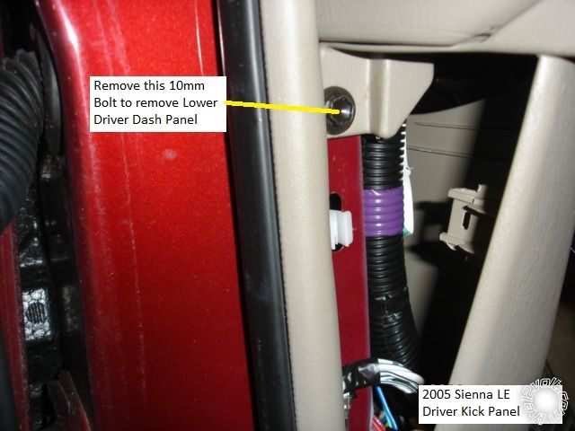
Remove the two 10mm bolts at each bottom corner of the Drivers Lower Dash Panel. Pull the
panel straight back. There are 3 snap fasteners along the top edge.
Remove the metal knee plate by removing the four 10mm bolts.
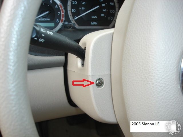
Remove the steering column cover ( both halves ) by positioning the steering in the 3 o'clock
and 9 o'clock positions and removing the Phillips screws. Fully extend the telescoping steering
wheel, gently separate the two halves and remove.
Here is a picture of the underside of the steering column.
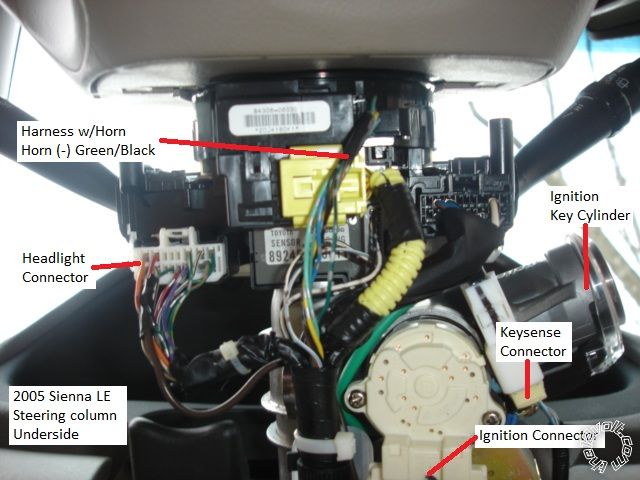
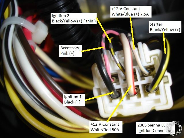
Here are the ignition wires.
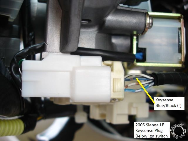
Here is the Keysense connector.
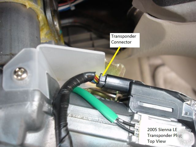
This is a top view of the steering column, over the ignition cylinder, of the transponder connector.
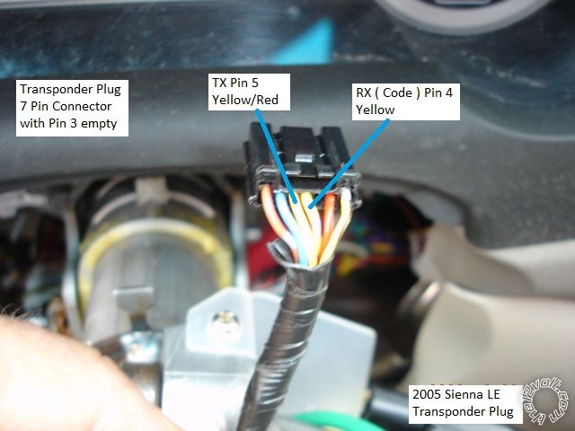
Below is the transponder connector unplugged with the wires marked.
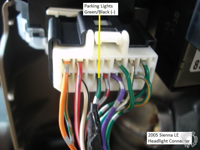
Here is the Headlight connector.
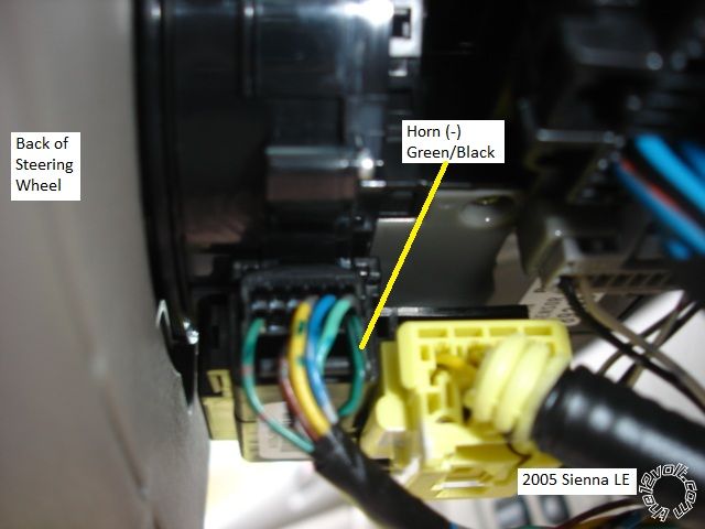
Below is the Horn wire.
Below are the lock wires in the Driver's Kick Panel.
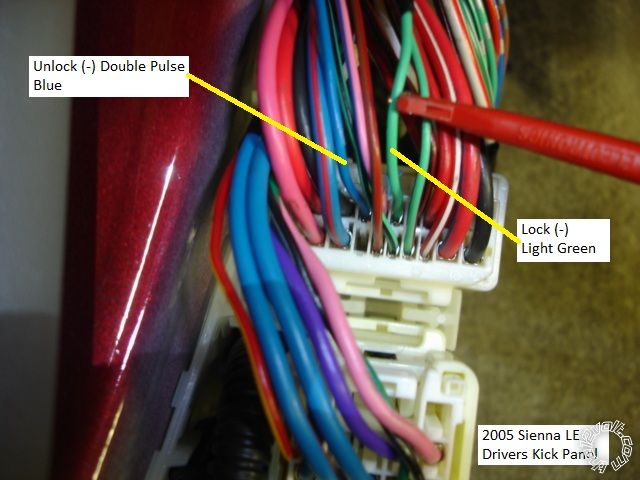
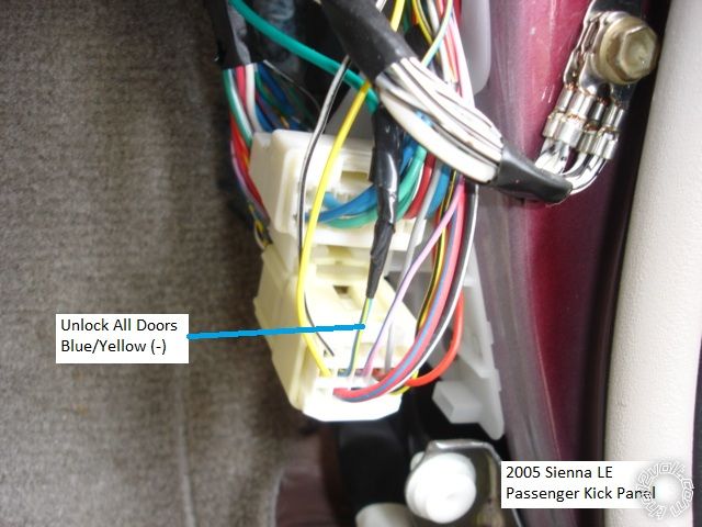
As noted, the Unlock wire requires a double pulse to unlock all the doors. If your R/S can't do this
or you prefer a single unlock pulse, below is a Unlock All wire in the Passenger Kick Panel.
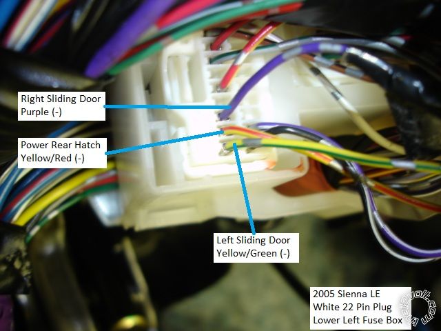
If your Sienna has power sliding doors & power rear hatch and your R/S system is capable, here
is a picture of the necessary wires.
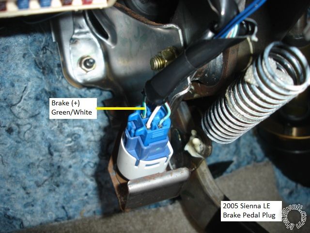
This is a picture of the Brake wire at the brake pedal connector.
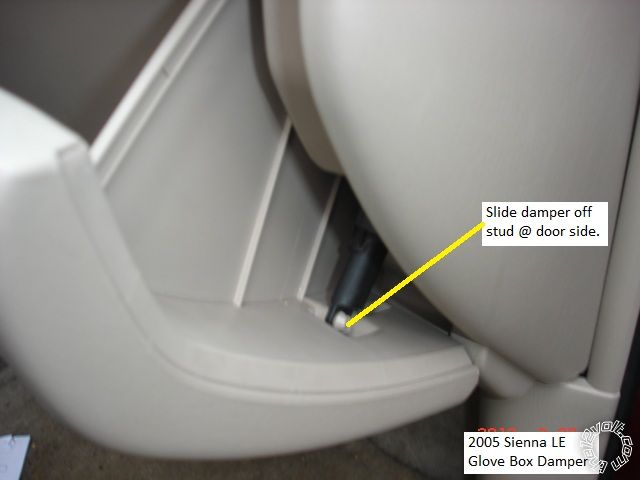
The ECM located behind the glove box has a Tach signal wire. To remove the glove box, release
this damper located on the right side of the glove box, then press in at both sides of the box while
opening further.
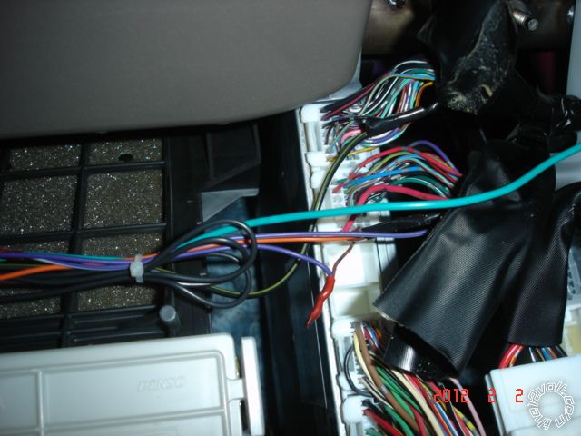
For improved access, you can also remove the upper mini-box by opening the door and pulling it
straight out of it's mounting recess. Below is a picture of the ECM.
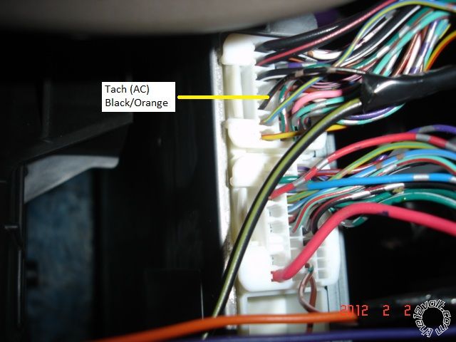
This is a picture of the Tach wire, BLACK/ Orange, top plug, Pin 5
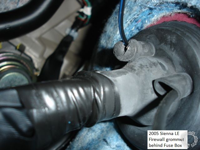
Here is a convenient firewall pass-thru grommet for the hood pin.
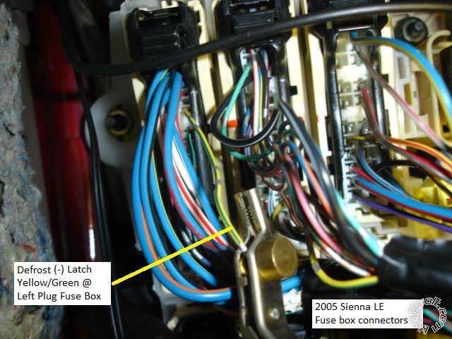
Bonus wire : Rear Defrost. Located in the pictured connector at the upper left of the fuse box.
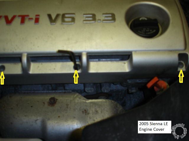
If you want, you can use a F.I. wire as the Tach source. Remove the engine cover by removing the
three Allen head nuts shown and lifting the cover off ( two latching clips at center ).
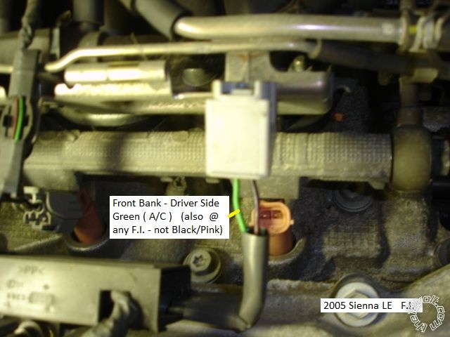
Here is a photo of a F.I. connector with the "uncommon" wire marked.
------------- Soldering is fun!
Replies:
Posted By: howie ll
Date Posted: March 24, 2012 at 8:55 AM
Very nice, just a technical note for anyone doing one of these for all bar North America, you will use the direction indicators rather than lights, go to the good quality photo (actually they are ALL good!) of the plug showing lights connection on the bottom row.
Look at the top row, right hand side from the right pins 1` and 3, GREEN/ black and GREEN/ YELLOW, both pos.
Alternatively, back of hazard switch, most late Toyotas grounding one of the leads for the length of time grounded, i.e. NOT latched, will activated the hazards.
If you split your (DEI) white lead do it via 2 x 1N5404 diodes.
They come with all the units for Europe.
-------------
Amateurs assume, don't test and have problems; pros test first. I am not a free install service.
Read the installation manual, do a search here or online for your vehicle wiring before posting.
Posted By: acosta1980
Date Posted: March 25, 2012 at 11:03 AM
VERY GOOD JOB BODY ------------- losminos n.c
Posted By: mduong25
Date Posted: October 27, 2014 at 12:01 PM
Do you know if we will need relays to drive the L/R sliding doors? What about relays for the trunk latch and rear defrost? Can you post a diagram of how the relays should be wired? I have a 2004 sienna. thank you so much!
Posted By: kreg357
Date Posted: October 27, 2014 at 6:34 PM
All of the item's you mentioned require only a low current ( 200mA ) (-) output signal to actuate. Not sure of the brand
and model of remote start system you intend to use, but most of them have that type of output for the Trunk Release,
2nd Unlock or AUX outputs. The Rear Defrost needs a Latched signal. That is an output that remains (-) for a set period
of time. A example would be an Avital 4103 system and it's BLUE/WHITE (-) 200mA 2ND STATUS/REAR DEFOGGER OUTPUT.
That wire is programmable to Defrost and can be set for either a single 1 second pulse output or a 10 minute Latched output.
The rear hatch unlocks with the doors. The Yellow/Red wire shown above is for van's that have the Power Rear Hatch option. ------------- Soldering is fun!
Posted By: mordechai
Date Posted: February 22, 2015 at 8:08 PM
I'm installing an avital 4103 on 2010 sienna it has a heavy gauge accessory wire do i connect it directly to the pink thin wire? also it doesn't have a transponder so how do i overrride the immobilizer?
Posted By: kreg357
Date Posted: February 22, 2015 at 9:14 PM
Toyota has been mixing in thin wires with the thick ignition wires for a while. The newer Toyota's have some very thin ignition wires.
Your Avital 4103 has 30 Amp ignition outputs. While it can be difficult ( and look strange ), you can connect these thick wires directly
to the vehicles' thin wires. I purchased several roll's of 16 gauge stranded wire with various color insulation ( Blue, Red, Yellow, Pink,
Green, White, Violet are the more common colors ) that I use in these applications. I cut the thick wire within 2 inches of the R/S plug
and solder the similar color 16 gauge wire on ( insulating with heat shrink tube ) to make the connection at the ignition switch. Makes
for a nice, neat install.
------------- Soldering is fun!
Posted By: mordechai
Date Posted: February 22, 2015 at 9:20 PM
thanks man
Posted By: aserynoum
Date Posted: January 04, 2016 at 11:14 PM
Thanks so much for this pictorial. Im installing one on mine and i used your help, but im facing a few problems. Would mean a lot if you could check out my thread, thanks!
Posted By: ojavery
Date Posted: January 12, 2016 at 5:04 PM
Wow,great tutorial! Can I get some help? I'm installing a crimestopper rs4g5 with a fortin evo ride. I have the fortin hooked up, that seemed surprisingly easy. I have what I need hooked up on the 12 wire of the cs now I know where to hook the tach . Now I have a 3 wire low currant plug(red). Blue/orange is start, or/wht is add,sign,aux2 and green is start activation. I don't have a push button start so do i need these? If so where should I hook them up? Now the locks, my instructions say there are 3 types of lock wiring, are toyotas neg trigger? Now the high currant 6 pin connector. Reds are obvious, straight to battery. Brown is starter power( power while cranking) where should I go with that? Grey wire is add, first key on and drops while cranking. Where should I go with this? Pink wire, ign output. Turns on in position 2 and stays on while cranking. Where do I go with this? Pink/wht wire. Multi function output, can be used for 2nd ign ,acc, or starter. What should I use this for? I have power sliders I would like to use. Thanks in advance for your help, I reallyappriciate it!!
-------------
o.j..
Posted By: kreg357
Date Posted: January 12, 2016 at 7:21 PM
CS RS4-G5 to 2004 Sienna
6 Pin Plug
Red x 2 to WHITE/ Red @ ignition switch harness
Brown to thick BLACK / YELLOW @ ignition switch harness
Pink to Black @ ignition switch harness
Grey to Pink @ ignition switch harness
Pink/White to thin BLACK / YELLOW @ ignition switch harness * Program to IGN2 = Default
The Red 3 Pin plug and its' wires are not needed for your minivan. Not used / do not connect.
The minivan has Type B or (-) negative triggered door locks. You can make a direct connection from the CS unit to the
minivan. Green to the Light Green (-) Lock wire in the DKP. Blue to the Blue (-) Unlock wire in the DKP and program the
CS for a double unlock pulse.
Does your van have right and left power sliding doors? Does it have power lift-gate? You only have 2 outputs from the CS.
You can use the Brown wire ( trunk release ) for one door.
You can use the AUX2 Orange wire ( or the ORANGE / White wire on Red 3 Pin plug ), when programmed, for the other door.
If your van has the Factory Alarm, you should connect the CS Yellow/Black GRW wire to the minivans Blue/Black Keysense
wire. I'm assuming you are going D2D to the EVO-Ride and the CS (-) GWR wire is available. ------------- Soldering is fun!
Posted By: ojavery
Date Posted: January 13, 2016 at 5:15 PM
Thank you so much for your help! That was exactly what I needed. Hard to believe I won't have to run anything thru the firewall. Since you have great knowledge of the cs and my van let me ask you one more question. The tach wire connection was holding me up too. I finally got it located. It's at the ecm on the passenger side. Is there a connection closer to the steering column that you know of? Thanks again, I really do appreciate it. O.J.
-------------
o.j..
Posted By: kreg357
Date Posted: January 13, 2016 at 6:07 PM
Not that I know of. Sometimes Pin 9 of the OBD2 plug ( if there ) will give a Tach signal on Toyota's, so you might try there.
Also be aware that on some Sienna's in that 2004 through 2007 time period, the Tach wire at the ECM is not there or at a
different pin location. Most R/S units give a fairly long Tach wire, but it should be no problem to extend it to reach.
-------------
Soldering is fun!
Posted By: ojavery
Date Posted: January 13, 2016 at 6:17 PM
OK, thanks again. I'll be finishing it up on Monday, I expect it will go well.
-------------
o.j..
Posted By: ojavery
Date Posted: January 18, 2016 at 6:50 AM
The c's yellow bulk wire I have hooked up to the bypass module, that was the instructions from fortin. What did you mean by you assume I'm going to d2d to the evo ride and the c's (-) gwr wire is available? ?
-------------
o.j..
Posted By: ojavery
Date Posted: January 20, 2016 at 3:49 PM
All done, went well. One more question. I used the brown wire for the right slider and that works when I use the truck button. I used the aux2 orange wire for the other sliding door. How do I use that door? I checked the programming and it said that is aux2 default. Thanks again for your help, it went really smooth because of your help. O.J.
-------------
o.j..
Posted By: kreg357
Date Posted: January 20, 2016 at 8:52 PM
I might be wrong on that Orange wire. I'm not a CrimeStopper user. Do you have a Cool Start or a ProStart unit? The CoolStart model can't change the function of the Orange wire to an AUX2 output while the ProStart models can. I was looking at the ProStart install guide for your questions.
-------------
Soldering is fun!
Posted By: ojavery
Date Posted: January 21, 2016 at 5:29 AM
I have a cool start system. No worries, the door I use the most is the one that's hooked up.
-------------
o.j..
|