The following write-up / pictorial is for a Remote Start with Keyless entry into a 2000 - 2002 Impala. No disassembly photos
are included. Instead, here is a link to a prior post that includes excellent info from forum member, flobee4.
https://www.the12volt.com/installbay/forum_posts.asp?tid=119995&tpn=1&PN=1
Additional disassembly info and sage advice from forum member Chris Luongo can be found in this prior post :
https://www.the12volt.com/installbay/forum_posts.asp?tid=94224&tpn=1&PN=1
( The above links confirm the value of the Search function.  )
)
This gen Impala has Passlock2 and a one-wire door lock system. Both are fairly easy to manage with relays and resistors but
there are many full featured, reasonably priced, bypass modules that handle this and more plus save time during the install.
All major bypass manufacturers have models available for this vehicle. To see exactly which features are supported and its'
install guide, here is a link to a popular choice from Fortin, the INT-SL+ bypass module : https://ifar.ca/download/3966/preview.html
As noted, this bypass module handles the Passlock2, door locks, trunk release and Parking Lights through its OBD2 Data
connection. It also provides a Tach signal but depending on the remote starter used, may not be required as this vehicle
has "one touch starting". ( A quick turn of the key to the START position and release will start the engine. )
This is a photo of the main ignition harness as seen from the drivers side.
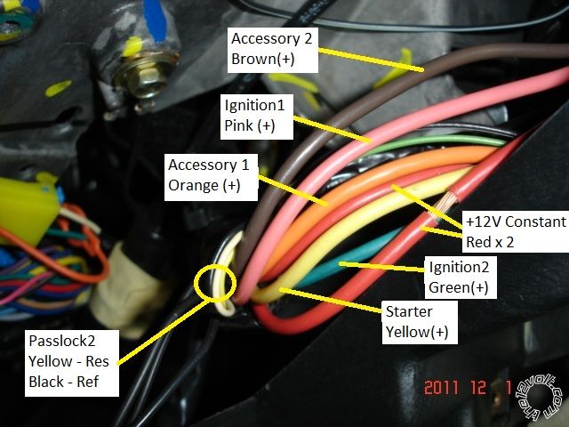
Note : This vehicle has two Ignition wires, one Starter wire and two Accessory wires. Most R/S units are capable of powering
4 of these 5 ignition wires, so an extra relay w/fuse might be required. Included below is a note from Omega concerning the
Brown Accessory2 wire : ** BROWN Must Be Power As Accessory to Prevent Check Engine or Air Bag Light
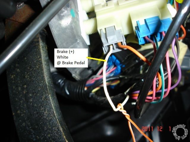
This is a picture of the Brake(+) wire.
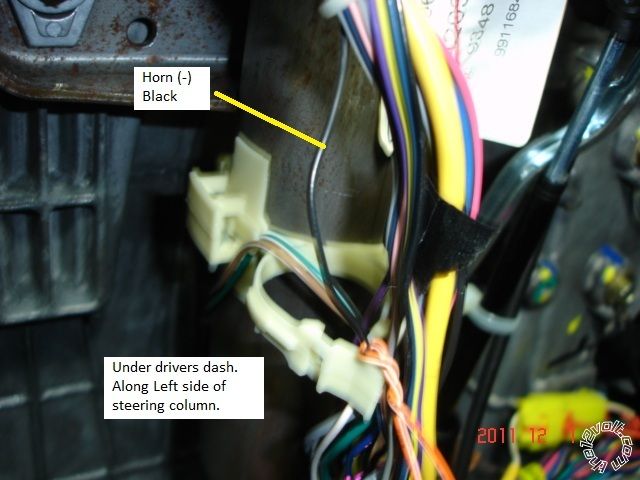
Here is a picture of the Horn wire.
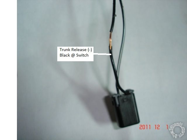
This is a picture of the Trunk Release wire at the trunk switch connector.
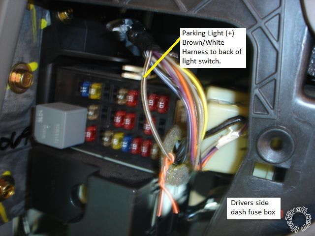
This is a photo of the Parking Light wire. Some guides list it as possibly Blue. Alternate location is the BCM. Either gold
bolt shown is a good place for the R/S Chassis Ground wire ( with soldered on terminal lug ).
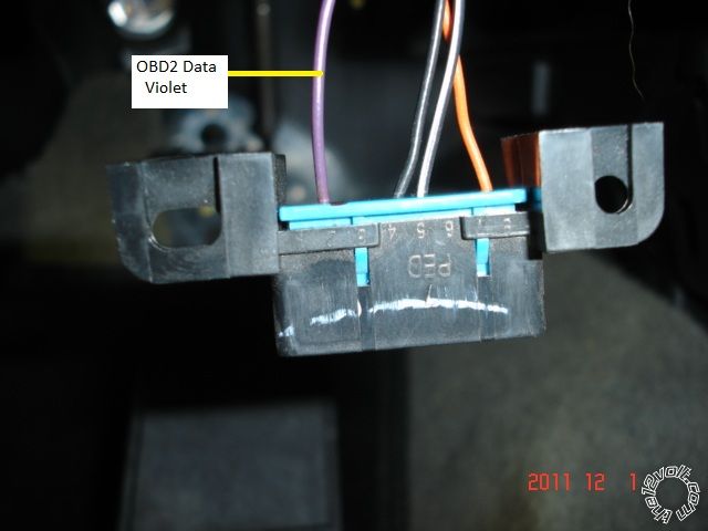
For those using a Data type bypass module, here is a photo of the Violet Data wire at Pin 2 of the OBD2 connector.
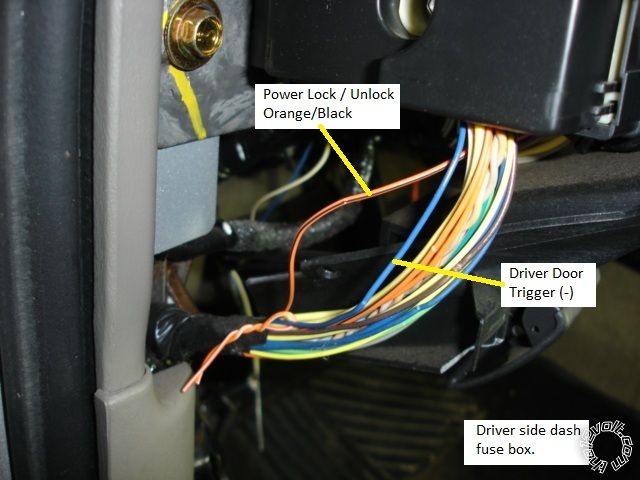
This is a picture of the Door Lock wire and the Door Trigger wire. Not shown, but in that same bundle of wires is the
Light Green Factory Alarm Disarm wire.
Not shown is a firewall pass-thru for the Hood Pin.
For those adventurous installers looking to do it the hard way ( and save some money, if not any time ), here are links to info
on the Passlock2 and door locks:
https://www.wiringinstructions.com/v2/diagrams200/238%20-%20General%20Motors%20Passlock%202%20Interface%20System.pdf
https://www.wiringinstructions.com/v2/diagrams200/217%20-%20Single%20Wire%20Resistor%20Door%20Locks.pdf
Lock = Ground though a 470 ohm resistor Unlock = Straight Ground
-------------
Soldering is fun!
MOST of that info applies up to the 05/06 body style change. Very good write up there!
I believe there is usually a light blue negative parking light wire also in that same harness as you show the positive lights.
Kregg, the picture of the OBD 11, if that orange wire is at pin 9 it's tach. If pin 8, shut up Howard.
-------------
Amateurs assume, don't test and have problems; pros test first. I am not a free install service.
Read the installation manual, do a search here or online for your vehicle wiring before posting.