2011 Hyundai Sonata Remote Start w/Keyless Pictorial
Printed From: the12volt.comForum Name: Car Security and Convenience - Alarm/Remote Start Pictorials
Forum Discription: Installer submitted Alarm, Keyless Entry, and Remote Start Pictorials from our Car Security and Convenience forum.
URL: https://www.the12volt.com/installbay/forum_posts.asp?tid=132478
Printed Date: May 21, 2026 at 10:45 PM
Topic: 2011 Hyundai Sonata Remote Start w/Keyless Pictorial
Posted By: kreg357
Subject: 2011 Hyundai Sonata Remote Start w/Keyless Pictorial
Date Posted: October 25, 2012 at 8:40 AM
2011 Hyundai Sonata remote start with keyless entry DIY pictorial.
Notes :
This was a basic U.S. domestic market Sonata GLS. This vehicle has a Factory Alarm and a standard key ( non-PTS ).
U.S. market Sonata's without Push To Start do not have a transponder immobilizer system, so no bypass module is
necessary. The Factory FOB's do not work while the engine is running so a R/S system with keyless entry is suggested.
The Factory Alarm will not trigger with just a remote start so a Disarm is only necessary with an Unlock or Trunk
Release. This vehicle does not have "one touch starting" so it is a candidate for Anti-Grind and Tach Mode starting.
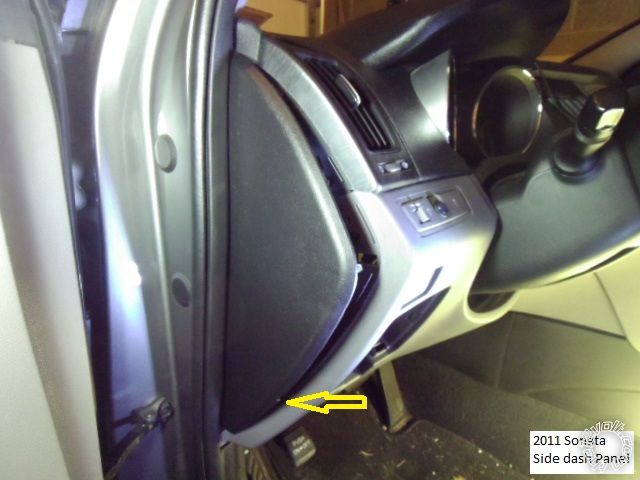
Disassembly :
Using a non-marring trim tool, remove the dash side panel. The arrow indicates a notch for trim tool insertion.
Remove the two screws indicated in this photo :
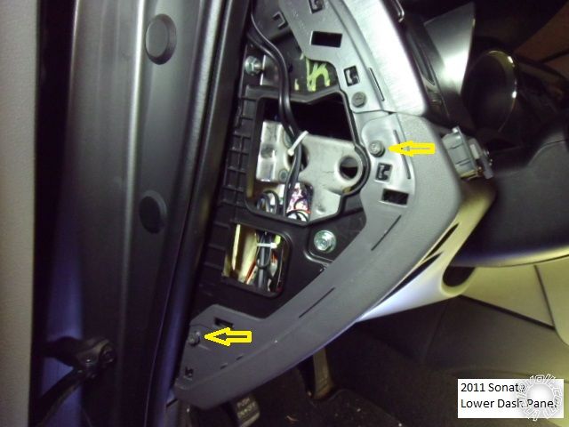
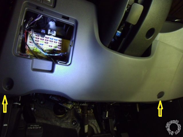
Remove the two screws shown in this picture and release the lower dash panel from the side and then pull straight
away from the dash. The are three retainer clips along the top edge.
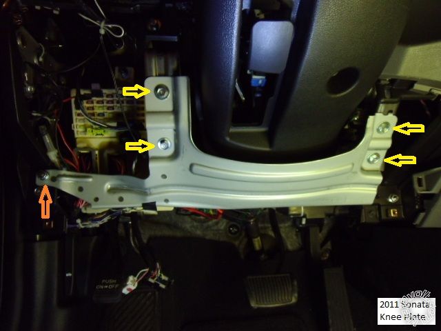
Remove the knee plate by removing the four 10mm bolts shown with Yellow arrows and the one 10mm nut shown
with the orange arrow.
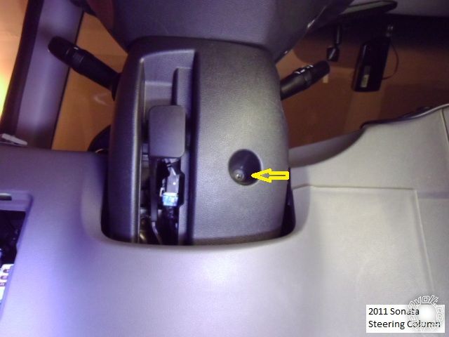
Remove the one screw shown at the underside of the steering column.
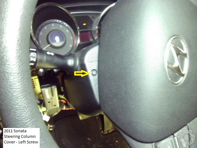
Remove two screws located at 3 and 9 O'Clock ( 3 O'Clock shown ). Then separate the upper and lower halves of the
steering column cover and remove both.
Not shown is the Drivers Kick Panel removal. The hood release lever is remover by compressing the pivot shaft fingers
and pulling the lever straight off the shaft. Remove the door sill trim by lifting it straight up then grasp the DKP
and remove it by pulling it back and away.
Wiring :
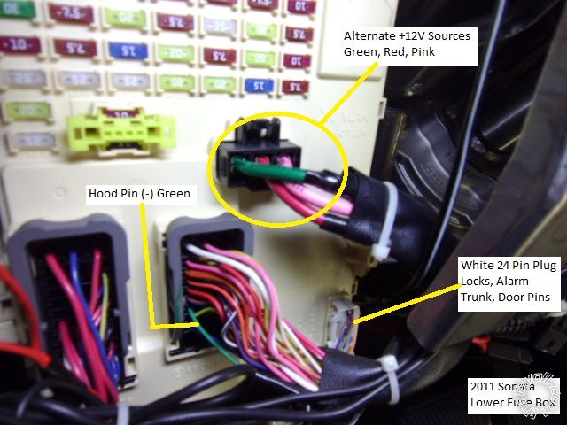
This is a picture of the lower right corner of the dash fuse box. The three wires in the Black plug are an alternate
+12V power source, each at 30 Amps. Close-ups to follow.
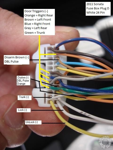
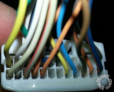
This is a close up of the White 24 Pin Plug with the wire marked.
This is a close-up of the Hood Pin wire.
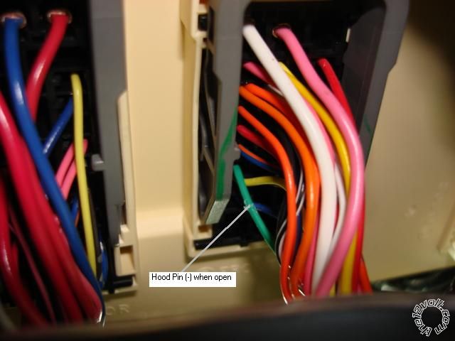
Here is a shot of the left side of the steering column.
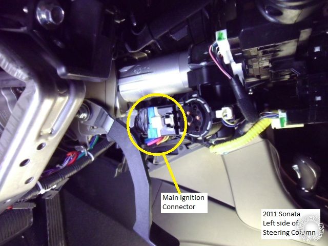
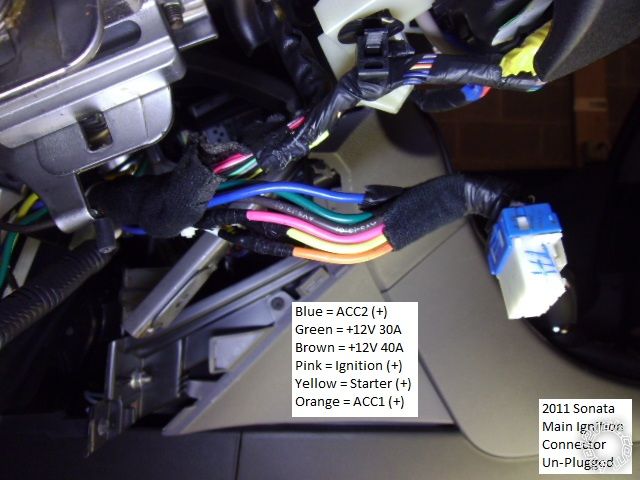
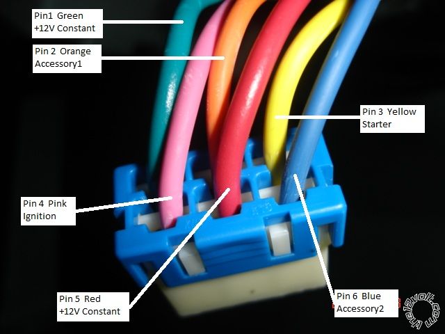
This is a close up of the Main Ignition Harness. Use caution / be gentle when disconnecting this plug, it can cause
the ignition switch to come apart.
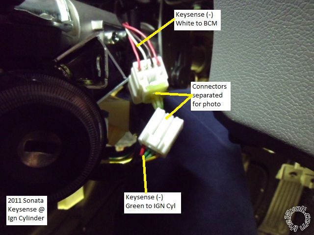
This is a picture of the Keysense wire at the right side of the steering column. Note that the wire color changes
at each side of the connector junction.
Here is a photo of the Driver Kick Panel area.

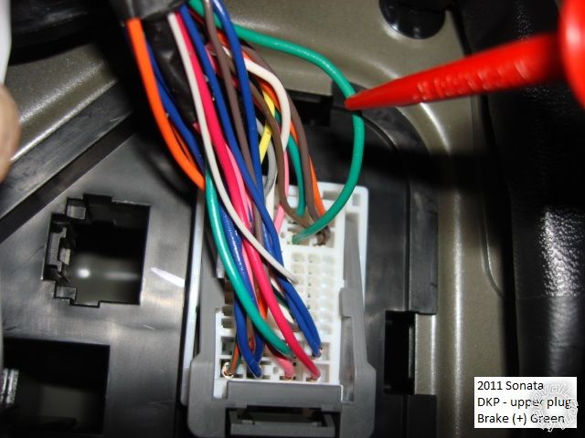
The Brake wire is located in the DKP, top plug, pictured below (close-up).
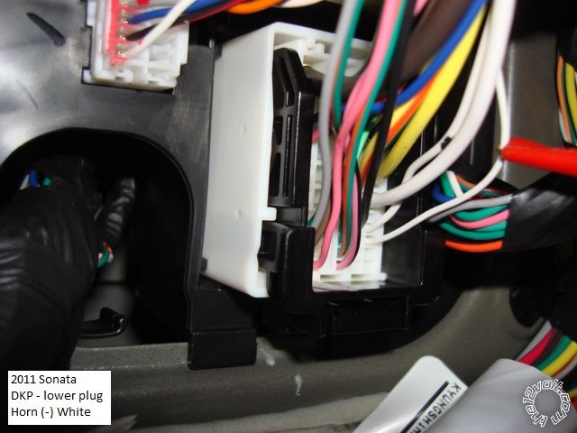
Also in the DKP, bottom plug, is the Horn wire (close-up).
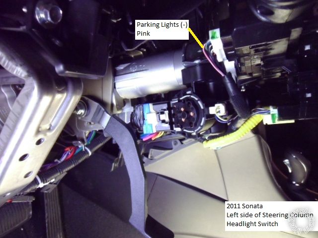
The Parking Lights can be found either at the Headlight Switch connector in the steering column...
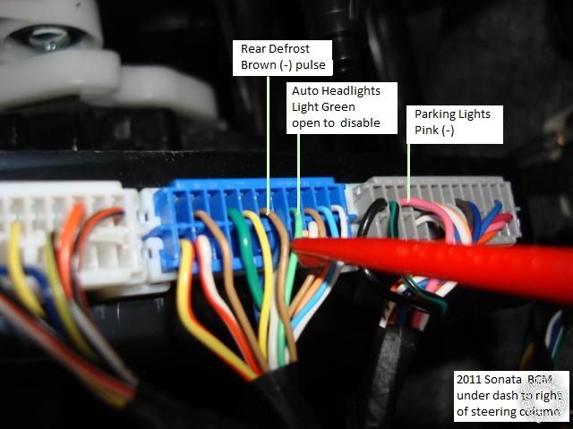
or the BCM, which in located under the dash to the right side of the steering column. Also shown is the Rear Defrost
wire and the Auto Headlights wire. The Rear Defrost requires a (-) pulse to turn on and will light the Defrost light
at the console switch. Another pulse will turn it off.
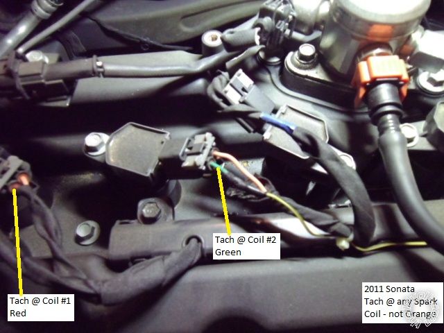
This is a picture of a Tach source, found at any Spark Plug Coil. ( Engine cover removed, lift straight up, retained
by four pins.)
Notes :
There are several large grommets located in the firewall for wire pass thru.
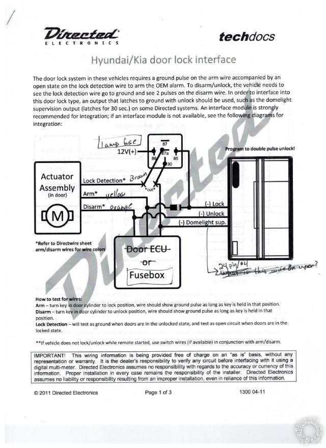
On this vehicle, a double pulse to the two Disarm wires ( Orange & Brown ) will also unlock the doors.
-------------
Soldering is fun!
Replies:
Posted By: shortcircuit161
Date Posted: October 25, 2012 at 8:57 AM
I did a 2010 a few months back but can't remember which colors it had on the ignition harness. I always test everything of course but was wondering on the difference.
-------------
Posted By: kreg357
Date Posted: October 25, 2012 at 11:42 AM
Hi Frank,
Thanks for catching my error. Somehow I got the two folders mixed up.  ( Teach me to forget the vehicle label in the corner...)
The top picture is correct for the 2011 Sonata. The Sonatas' two +12V constant wires are Green and Brown, both rated at 40 Amps. The second picture is from a 2012 KIA Optima. Aside from the Red vs Brown color change, everything else, including the pin locations on that plug, is the same. Sister cars but slightly different.
Sorry for the confusion, wish I could edit that second picture out.
Kreg
-------------
Soldering is fun!
Posted By: shortcircuit161
Date Posted: October 25, 2012 at 11:56 AM

Thanks again for the great writeup!!!
-------------
Posted By: mjperk
Date Posted: December 28, 2012 at 3:03 PM
https://www.advancedkeys.com/Prod_AK104B.html
They have 2 manuals on that page that show how to install the system (in a basic way), and most of the wires match up with what you have here. There are just a few wires that aren't mentioned and I'm wondering if you can help me out. Just for reference--I have a 2011 GLS with a M/T. If you have the time, go read the descriptions of the connections of the manuals located at that link--it will help clarify which connections I'm referring to.
1.) ON 2/2nd Ignition Output -- If you look at the manual it says "if applicable." I see an "Ignition +" wire in your picture so is this just the "ON 1/Primary Ignition Output" and there is no 2nd output?
2.) Bypass Module Control -- The manual mentions keysense input. Do I need to worry about this wire or is it extra? I only see a few keysense wires on your diagram and wasn't sure if those were the ones I'm looking for. What does keysense do for the GLS?
3.) Ground When Running -- Again, this mentions keysense. Do you know where this is?
4.) Neutral Safety Switch -- Since I have a manual transmission this would be important. Do you have any idea what wire it might be?
5.) Parking Lights x2 -- The parking lights you call out are negative I believe. If you look at the manual this calls for a positive side. It says "connect the positive side of parking lights or the hazard light switch for same effect." Is this wire located in the same area?
6.) Lock & Unlock -- Your pictures show a 24 pin plug that lists door triggers as well as trunk, lock, unlock. Are the triggers just the switches in the door, or are they used for the alarm, or are they connections to some sort of lock solenoids? I got a little confused here. I'm assuming that the lock & unlock are NOT the triggers (I'm assuming lock & unlock goes to the solenoids) but wanted to make sure as apparently this connection goes to the lock/unlock signal wires.
7.) Door Switch -- I'm assuming this is the door trigger I just mentioned? It says to "connect to vehicle's door open signal wire." If you look at the manual there is only 1 wire, so would you just pick the driver's door and hook it up to that?
Sorry for my huge post, but I'd appreciate any help you can give!
Posted By: kreg357
Date Posted: December 28, 2012 at 5:36 PM
OK. The pictorial was on a Sonata GLS with Automatic Transmission. From your description, your car has a Manual Transmission. No
mention was made and your profile info does not give a location but if this is a U.S. market vehicle there will be no transponder based
ignition immobilizer system installed. However, if this is a Canadian market vehicle, then it will have a transponder system and need a
bypass module.
My main issue with this setup is the remote start function. It appears that the Advanced Keys system has no specific Manual Transmission
Reservation Mode like a manual transmission safe remote start system. The Manual Transmission Reservation Mode ensures the vehicle is
left in neutral upon vehicle exit and then shuts down the engine and locks the doors. All this is done to prevent the engine from being remote
started with the transmission in gear. It's a very important safety issue because the clutch interlock switch must be bypassed to allow a remote
start ( the vehicle thinks the clutch is depressed even though there is no one in the vehicle and the clutch pedal is not actually depressed ).
Forum rules forbid discussions on installing a non-manual transmission safe remote start system into a manual transmission vehicle. We
do have an authorized dealer for this product that is an active forum member and perhaps he can shed some light on this product.
If the vehicle has a true Neutral Safety signal output, there is a way to do the install. Without that signal, forum rules prevent too much
discussion on this topic / install. Installing the Keyless entry module is fine. Adding the PTS module would be OK as long as you only
used it as a PTS switch from inside the car while manually depressing the clutch pedal, not for remote starting.
On to the Questions ( I am going by the info in the product install guides, I have never seen / installed / used these items ) :
1.) The vehicle only has one Ignition wire. Your aftermarket system has two available but only one will be needed.
Please note that the vehicle has two Accessory wires and the aftermarket system only has one Accessory Output. Additionally
the install guide has a cut key blade inserted into the ignition switch and left in the ACC position with the Accessory wire
interrupted with a switch. In your case you would need to interrupt two Accessory wires with switches and use an extra external
relay to power the second Accessory wire during a PTS.
2.) If you have a US market vehicle no bypass module is required and this wire would be "not used".
3.) Yes, connect the GWR wire to the Keysense wire shown in the pictorial.
4.) NSS Here is where the fun begins. Your vehicle has a manual transmission and to start the vehicle, you must depress the clutch
pedal. Your aftermarket system has a remote start capability but IMHO is not actually designed for a Manual Transmission vehicle.
Your PTS system should only be installed if you can locate an actual Neutral Safety signal that outputs a (-) signal when the transmission
is in neutral. I can not find any wire guide listing for an actual Neutral Safety wire.
5.) The Pictorial shows the (-) Parking Light wire and most installers would use a relay to convert the AK104's (+) Parking Light output
to the desired (-) signal the vehicle needs. But you can do it another way, using the two AK104 (+) Parking Light wires with this info :
Parking Lights (+) GREEN/ Black + (Left), BROWN / Black + (Right) @ dash fuse box, Black 39 pin plug (A), pins 25 and 7
6.) Your AK104 system does not have a separate Factory Alarm Arm and Disarm output, only Lock and Unlock. This will make it difficult
to control these functions. Disarm requires a Double Pulse that is possible with the proper setting of JP3 on the AK104 but will require
diodes to split the Unlock output wire into three legs going to three wire locations on the white 24 pin plug shown. Factory Alarm Arm
is a whole different story. It will require a SPDT relay and diodes, wired to open a vehicle wire and pulse another, as indicated below :
Factory Alarm Arm Yellow and Brown, (-) and open @ dash fuse box, White 24 pin plug (D), pins 15 and 22
Also remember that a Disarm is required before a Trunk Release or the Factory Alarm will be triggered.
7.) While the AK104 only has one Door Trigger Input, you should monitor all four doors, the trunk and the hood. To do this split the AK104's
Door Trigger Input wire into 6 leads using the standard 1N400x diode ( band towards the AK104 ) and connect to the vehicles trigger
wires ( leave JP1 set to - ).
Considering all the above, especially the vehicles manual transmission & Factory Alarm and needed relay circuits and diodes, I would suggest
bringing this to a trained / certified installer.
-------------
Soldering is fun!
Posted By: offroadzj
Date Posted: December 28, 2012 at 8:56 PM
kreg357 wrote:
On to the Questions ( I am going by the info in the product install guides, I have never seen / installed / used these items ) :
1.) The vehicle only has one Ignition wire. Your aftermarket system has two available but only one will be needed. Please note that the vehicle has two Accessory wires and the aftermarket system only has one Accessory Output. Additionally the install guide has a cut key blade inserted into the ignition switch and left in the ACC position with the Accessory wire interrupted with a switch. In your case you would need to interrupt two Accessory wires with switches and use an extra external relay to power the second Accessory wire during a PTS.
If you use the cut key turned to ACC method then yes you will have to interrupt both accessory wires. It's as simple as just cutting the wires and tying your new connections into the wire that goes towards the vehicle (not the switch side). On mine, I interrupted all of the wires so there was no issue of someone figuring out there was a 'key' in the ignition and stealing the vehicle (no immobilizer to prevent it). However, and I could be mistaking on this, I am fairly certain there is either a jumper setting or a programming option to change the ON2 to an accessory output... but my install guide that I had for it has disappeared on me and I can't get access to a guide at the moment. Check through the directions to be sure. If not then you will have to use a relay.
2.) If you have a US market vehicle no bypass module is required and this wire would be "not used".
This is 100% correct. You can do a quick test by completely covering the head (plastic part) of the key in tin foil and trying to start the car. If it starts and runs more than 2 minutes then there is no chip and no bypass is required.
3.) Yes, connect the GWR wire to the Keysense wire shown in the pictorial.
Make sure to cut the keysense wire and connect this to the vehicle side of the keysense wire. Also be careful because there are 2 wires that can be used for keysense or bypass. One is (+) and one is (-). Make sure to use the correct wire depending on the keysense wire (+0 vs (-)
4.) NSS Here is where the fun begins. Your vehicle has a manual transmission and to start the vehicle, you must depress the clutch pedal. Your aftermarket system has a remote start capability but IMHO is not actually designed for a Manual Transmission vehicle. Your PTS system should only be installed if you can locate an actual Neutral Safety signal that outputs a (-) signal when the transmission is in neutral. I can not find any wire guide listing for an actual Neutral Safety wire.
From what I have heard from my tech support as well as what I can see in the instructions, the remote start function is NOT designed for manual transmissions. It MUST be disabled on any manual transmission to ensure yours, your neighbors, and anyone around your car's safety. If it is left activated, the car will start and drive away if left in gear. The instructions show you how to disable the remote start function. Make sure to actually disable it (test to be sure) and not just "not use it" because the buttons can be pressed while in your pocket and bad things WILL happen.
5.) The Pictorial shows the (-) Parking Light wire and most installers would use a relay to convert the AK104's (+) Parking Light output to the desired (-) signal the vehicle needs. But you can do it another way, using the two AK104 (+) Parking Light wires with this info :
Parking Lights (+) GREEN/ Black + (Left), BROWN / Black + (Right) @ dash fuse box, Black 39 pin plug (A), pins 25 and 7
The easiest way would most likely be to connect the dual positive parking light wires as it would save a possible failure point (the relay) and give you less items to have to tuck away in the dash. The 2 AK components will be tricky enough depending on the space you have available.
6.)Your AK104 system does not have a separate Factory Alarm Arm and Disarm output, only Lock and Unlock. This will make it difficult to control these functions. Disarm requires a Double Pulse that is possible with the proper setting of JP3 on the AK104 but will require
diodes to split the Unlock output wire into three legs going to three wire locations on the white 24 pin plug shown. Factory Alarm Arm is a whole different story. It will require a SPDT relay and diodes, wired to open a vehicle wire and pulse another, as indicated below :
Factory Alarm Arm Yellow and Brown, (-) and open @ dash fuse box, White 24 pin plug (D), pins 15 and 22
Also remember that a Disarm is required before a Trunk Release or the Factory Alarm will be triggered.
This is 100% correct
7.) While the AK104 only has one Door Trigger Input, you should monitor all four doors, the trunk and the hood. To do this split the AK104's Door Trigger Input wire into 6 leads using the standard 1N400x diode ( band towards the AK104 ) and connect to the vehicles trigger wires ( leave JP1 set to - ).
Again, this is 100% correct.
Considering all the above, especially the vehicles manual transmission & Factory Alarm and needed relay circuits and diodes, I would suggest
bringing this to a trained / certified installer.
If you have never done a remote start I would HIGHLY HIGHLY HIGHLY suggest taking this man's advice. As an experienced installer (well over a thousand remote starters), I had some minor trouble installing the AK104B (along with a Compustar Alarm / Remote start system) on my own vehicle. It took me just shy of 5 hours to get everything finished... and then it still needed some tweeking.
-------------
Kenny
Owner / Technician
KKD Garage LLC
Albany, NY 12205
Posted By: offroadzj
Date Posted: December 28, 2012 at 8:57 PM
-------------
Kenny
Owner / Technician
KKD Garage LLC
Albany, NY 12205
Posted By: mjperk
Date Posted: December 29, 2012 at 6:50 PM
I do not have any experience exactly like remote starters, but I have done stereo and security system installs. I am a mechanical engineer by profession so I have a decent understanding of systems and if not have a desire to learn, but that being said I don't have any specific knowledge of these installs exactly.
I'd prefer to do the install myself to avoid the $400 install fee and am determined to figure out what it will take if at all possible. I also have very little faith with most of the installers around here. I took my car (probably over 8 years ago) to a Best Buy to have them install my first car alarm--I'll never go back there again. I figure that my time researching how to do it is better than spending money for them to do it wrong. I do appreciate your input though and feel like I have 95% of it figured out. I just want to make sure I get the last 5% correct... So regarding my questions:
1.) I emailed the manufacturer and they said "yes" just use the one wire that the car has and to leave the other one blank. I'm not sure if they just didn't want to deal with my question and gave me a quick answer or if it really is only necessary to use one wire. Why does the car have two accessory wires? Would you mind quickly explaining how this system is meant to work? I understand that accessory wires are meant to only provide power when the is in the ACC or ON position, but I don't get why there would be two.
"It's as simple as just cutting the wires and tying your new connections into the wire that goes towards the vehicle (not the switch side)."
I'm unclear why I have to interrupt both accessory wires. Why can't I just pick one and use that to power the system? Also, what new connections are you talking about? Sorry but you guys kind of lost me here so could you try to explain this one again?
2.) Yes, I have a US Sonata so this will just be unconnected.
3.) The GWR wire is a (-) so are you saying connect the "Keysense white (-) to BCM" to this wire? Offroadzj says that there are two wires but upon a quick glance I only see that (-) wire that I just mentioned.
4.) I understand the importance of making sure this is connected to a neutral signal. It was mentioned that the car would "take off" if it was left in gear and remote started. In regard to Offroadzj's comments, wouldn't this neutral signal ensure that the horror story so to speak wouldn't happen though? I figured that essentially the system would only remote start if it was receiving a signal that the car was in neutral. Along with that there was a mention of how the clutch needs to be pushed in to start the car. Would this be bypassed by a remote start so that in theory if it received a signal that the car was in neutral, it would start without the clutch being depressed?
5.) That makes sense
6.) I'm a little bit confused--there is a mention of diodes again. Is this only required for unlocking and disarming with one button push? For instance, if I wanted to unlock the alarm with a button push and then unlock the door with another push would this still require diodes? I got a bit confused with this explanation--could you please clarify a bit more on this one? I have little knowledge of selecting/wiring relays and don't know which 3 wires you're talking about. What is a "DBL pulse" anyway? Sorry, but this one is what I feel least confident about and am hoping you can clarify the most on.
7.) Being that my background is with mechanical systems I just want to clarify. From what I understand diodes essentially make current flow in only one direction. So would you accomplish the suggested system by putting the diode into the circuit as follows:
6 inputs -> diode -> Door switch input on aftermarket system
Essentially you're splicing 6 wires to the diode and then to the system input? Also, which diode would you recommend for the "x"?
I really appreciate all your help and just want to consider everything before hand so that I can decide if I really need to have a pro do the install. Like I said, I'm handy and think I can figure it out with some help--I'd really like to get the knowledge and learning experience too. Thanks again guys.
Posted By: offroadzj
Date Posted: December 29, 2012 at 9:09 PM
mjperk wrote:
Sorry about my lack of information. I actually created the account to respond to this specific post because it contained so much helpful information regarding installs of this nature. I live in Des Moines, IA.
I was hoping you were a little closer to the Tri-state area. As far as I know, I am the only their only retailer in the Northeast... but that doesn't help you out much where you are... lol
I do not have any experience exactly like remote starters, but I have done stereo and security system installs. I am a mechanical engineer by profession so I have a decent understanding of systems and if not have a desire to learn, but that being said I don't have any specific knowledge of these installs exactly.
I'd prefer to do the install myself to avoid the $400 install fee and am determined to figure out what it will take if at all possible. I also have very little faith with most of the installers around here. I took my car (probably over 8 years ago) to a Best Buy to have them install my first car alarm--I'll never go back there again. I figure that my time researching how to do it is better than spending money for them to do it wrong. I do appreciate your input though and feel like I have 95% of it figured out. I just want to make sure I get the last 5% correct... So regarding my questions:
As long as you take your time (plan for at least 4-5 hours so you don't have to rush), test EVERYTHING, and make the proper connections, you should have no issues.
1.) I emailed the manufacturer and they said "yes" just use the one wire that the car has and to leave the other one blank. I'm not sure if they just didn't want to deal with my question and gave me a quick answer or if it really is only necessary to use one wire. Why does the car have two accessory wires? Would you mind quickly explaining how this system is meant to work? I understand that accessory wires are meant to only provide power when the is in the ACC or ON position, but I don't get why there would be two.
"It's as simple as just cutting the wires and tying your new connections into the wire that goes towards the vehicle (not the switch side)."
I'm unclear why I have to interrupt both accessory wires. Why can't I just pick one and use that to power the system? Also, what new connections are you talking about? Sorry but you guys kind of lost me here so could you try to explain this one again?
The vehicle uses 2 separate ACC wires to power the components. Some of the components will run off the one accessory (ie heater, etc) and some will run off the 2nd accessory wire (radio, etc). Therefore both HAVE to be connected. There is no way around it. They also both HAVE to be interrupted otherwise when you turn the cut key to ACC for the steering column unlock, you will be powering a circuit at all times and your battery will go dead. Unfortunately there is no way around using the relay to power the 2nd ACC wire. I am not sure why they told you that you didn't...
2.) Yes, I have a US Sonata so this will just be unconnected.
Correct. That will make things a little easier.
3.) The GWR wire is a (-) so are you saying connect the "Keysense white (-) to BCM" to this wire? Offroadzj says that there are two wires but upon a quick glance I only see that (-) wire that I just mentioned.
I didn't have the vehicle wiring in front of me. If the Keysense wire in the vehicle is (-) then that is the one you will use off the AK. Had it been a (+) keysense, then you would have had to use the other wire (bypass wire). To make the connection, cut the keysense wire in the vehicle and connect the AK to the BCM side (not the key side). If you cannot tell which is the key side vs the BCM side, after cutting it insert a key and use the meter to determine which side of the wiring shows a (-) signal. Once you found that, tape that one off and use the non (-) side to connect the AK wire to.
4.) I understand the importance of making sure this is connected to a neutral signal. It was mentioned that the car would "take off" if it was left in gear and remote started. In regard to Offroadzj's comments, wouldn't this neutral signal ensure that the horror story so to speak wouldn't happen though? I figured that essentially the system would only remote start if it was receiving a signal that the car was in neutral. Along with that there was a mention of how the clutch needs to be pushed in to start the car. Would this be bypassed by a remote start so that in theory if it received a signal that the car was in neutral, it would start without the clutch being depressed?
The reason I said you will need to disable the remote start is because as far as I know, there is no neutral safety switch wire in the vehicle that determines if the vehicle is in gear or not. Without this wire, there is no other way to connect the neutral safety wire of the AK and no safe way to be able to use the remote start feature. However, if you happen to find a neutral safety switch wire in the vehicle then you will be able to use that wire and therefore be able to keep the remote start function enabled... but I really don't think you will. If you do find one, you will need to bypass the clutch switch, but we can go over that if you find the neutral safety switch wire. If it is like I think, and there is no neutral safety switch, you will have to disable the remote start feature.
5.) That makes sense
Sounds good.
6.) I'm a little bit confused--there is a mention of diodes again. Is this only required for unlocking and disarming with one button push? For instance, if I wanted to unlock the alarm with a button push and then unlock the door with another push would this still require diodes? I got a bit confused with this explanation--could you please clarify a bit more on this one? I have little knowledge of selecting/wiring relays and don't know which 3 wires you're talking about. What is a "DBL pulse" anyway? Sorry, but this one is what I feel least confident about and am hoping you can clarify the most on.
The vehicle has a separate wire for unlock and another wire for disarm. In addition, there is a 3rd 'lock sense' wire that needs to be interrupted or grounded for arming / disarming the alarm. Before going too far into this, you will want to test to see if the vehicle even has a factory alarm. Close the door with the window open and press the lock button on the factory remote at least twice. Then wait at least 1 minute and then unlock and open the door from the inside handle. If the horn sounds then you have a factory alarm and you will HAVE to wire it up through a series of diodes and relays.... it's not an easy setup to do and can be a royal PITA even for an experienced installer.
7.) Being that my background is with mechanical systems I just want to clarify. From what I understand diodes essentially make current flow in only one direction. So would you accomplish the suggested system by putting the diode into the circuit as follows:
6 inputs -> diode -> Door switch input on aftermarket system
Essentially yes, the diode is nothing more than an electrical one way 'valve'. However, depending on the signal (+) vs (-), depends on which way the band of the diode faces. With the door pin wires (all (-) signals), you will want all of the bands facing towards the AK unit. So it will be: AK Input --> 6 diodes (band towards AK unit) --> one diode to each door / trunk input.
Essentially you're splicing 6 wires to the diode and then to the system input? Also, which diode would you recommend for the "x"?
Not quite. You are actually splicing 1 diode to each vehicle input (doors, trunk, etc) then splicing the 6 diodes together into the AK input. As far as the diodes go, the 1N4001 or 1N4004 should be fine.
I really appreciate all your help and just want to consider everything before hand so that I can decide if I really need to have a pro do the install. Like I said, I'm handy and think I can figure it out with some help--I'd really like to get the knowledge and learning experience too. Thanks again guys.
It is 100% do-able, but it is not one of the easier ones. Definitely plan for many hours and a few headaches along the way. Test EVERYTHING and verify everything again before making your connections. We are here (as much as possible) when you have questions.
To help make things a little easier, do the test I listed above regarding the factory alarm. That will tell us if we need to bother with the diodes / relays or not for the lock / unlock wiring.
-------------
Kenny
Owner / Technician
KKD Garage LLC
Albany, NY 12205
Posted By: bseal
Date Posted: March 27, 2013 at 10:52 AM
Sorry if this is confusing...
-------------
- Brian
Posted By: kreg357
Date Posted: March 28, 2013 at 9:41 AM
Hi Brian,
It sounds like you would like to fabricate a "T-Connector" for the various harnesses that
must be spliced into for the remote starter / alarm systems' connections. While this was
done for the ignition harness of some very popular vehicles by Bulldog Security, it has
faded away due to the ever changing plugs and connectors used. Here is a link to Bulldog
Security's current offerings : https://www.bulldogsecurity.com/Category/1020-t-harnesses.aspx
They don't list the Sonata, but if this "T-Connector" matches your idea, it might be possible to
do but very expensive.
Some vehicle manufacturers have a connector repair kit available at the parts counter that
would provide you the harness end connector. However finding the connector style physically
located in the fuse box assy or other computer modules ( BCM, ECM, etc. ) could be a problem.
That being said, a search of the WEB turned up this site : https://www.aeromotive.us/product_connectors.html
From their info, it appears that they might be able to supply you the connectors you seek, with
some limitations ( Connectors with over 6 cavities will only come with 6 wire leads ). I have never
dealt with them and don't know their policies ( they might have a minimum qty per order, etc ).
There are many harnesses tapped into ( looks like 9 in the pictorial ) and most of them are more
that 6 pins so you will need to ask for extra M & F pins, if they won't supply fully pinned connectors.
Good luck and please provide an update with you results.
-------------
Soldering is fun!
Posted By: howie ll
Date Posted: April 08, 2013 at 9:45 AM
Shouldn't the diode bands be towards the switches and AWAY from the unit.
-------------
Amateurs assume, don't test and have problems; pros test first. I am not a free install service.
Read the installation manual, do a search here or online for your vehicle wiring before posting.
Posted By: sakamakik
Date Posted: December 25, 2013 at 9:48 PM
What I bought.
1) Avital 4103LX Remote Start System with Two 4-Button Remote ($38.58)
2) Xpres DBALL Kit Databus all Interface Module ($44.47)
3) Directed Electronics Inc XKLOADER2 XpressKit ($26.49)
Including Tax & Shipping, total cost was $148.59 (by amazon.com)
Here is the wiring diagram.
https://dl.dropboxusercontent.com/u/12288608/Wiring.pdf
Posted By: kreg357
Date Posted: December 26, 2013 at 6:55 AM
Wow, very nice diagram!  The Avital 4103 is a good system and should perform well.
Only a few things to make note of.
1. The main purpose of the DB-ALL is the transponder by-pass. While the U.S. market vehicles do not have this transponder
based ignition immobilizer system, the Canadian market vehicles do. The added plus with the DB-ALL is that it will handle many
other functions for you and save time during the installation. ( Locks, alarm, tach, trunk release, etc ) The XKLoader2 cable is
used to flash the DB-ALL with the correct firmware, 401.HKHT1 v1.09.
2. While you could go with the D2D connection between the 4103 and the DB-ALL, going with W2W connections, as shown in the
excellent diagram will absolutely work flawlessly.
The only additions I would make, although not shown in the DB-ALL install guide, would be to use the 4103's Pink/White Flex
Relay output for the vehicles Blue Accessory2 ignition wire. It's there and this will completely duplicate a normal key start.
Program the Avital Menu 2, Item 6 to Option 2.
I believe the Canadian vehicles have a similar Parking Light system, so setting the 4103 for (-) Parking Light output and connecting
the 4103's White H1/9 Parking Light wire to the Sonata's Pink wire shown in the Pictorial will give Parking Light confirmation.
And lastly, the 4103's Brown H1/6 Horn Output wire is an optional connection for those that want audible command confirmation
and use of the Avital's Panic Mode. Connect this wire to the Sonata's White wire shown in DKP and use the Avital's Menu 1, Item 1
options to set the desired horn beep output length.
Very nice diagram and a great addition to this Pictorial for the Canadian market vehicles. Thanks! 
-------------
Soldering is fun!
Posted By: willny89
Date Posted: January 23, 2014 at 4:13 PM
I was hoping to get pointed in the right direction on which wire/fuse I should be looking for before I go on a wild goose chase. Thanks for the article.
Posted By: kreg357
Date Posted: January 23, 2014 at 5:46 PM
see if there were fuses for the Ignition output wires. My first thought would be that perhaps your 2012 vehicle was still covered
by the Hyundai warranty and a trip to the dealer would be the best first option.
-------------
Soldering is fun!
Posted By: trynastaytuned
Date Posted: November 09, 2014 at 8:45 AM
kreg357 wrote:
2011 Hyundai Sonata remote start with keyless entry DIY pictorial.
Notes :
This was a basic U.S. domestic market Sonata GLS. This vehicle has a Factory Alarm and a standard key ( non-PTS ).
U.S. market Sonata's without Push To Start do not have a transponder immobilizer system, so no bypass module is
necessary. The Factory FOB's do not work while the engine is running so a R/S system with keyless entry is suggested.Â
The Factory Alarm will not trigger with just a remote start so a Disarm is only necessary with an Unlock or Trunk
Release. This vehicle does not have "one touch starting" so it is a candidate for Anti-Grind and Tach Mode starting.Disassembly :
Using a non-marring trim tool, remove the dash side panel. The arrow indicates a notch for trim tool insertion.
Remove the two screws indicated in this photo :
Remove the two screws shown in this picture and release the lower dash panel from the side and then pull straight
away from the dash. The are three retainer clips along the top edge.
Remove the knee plate by removing the four 10mm bolts shown with Yellow arrows and the one 10mm nut shown
with the orange arrow.
Remove the one screw shown at the underside of the steering column.
Remove two screws located at 3 and 9 O'Clock ( 3 O'Clock shown ). Then separate the upper and lower halves of the
steering column cover and remove both.
Not shown is the Drivers Kick Panel removal. The hood release lever is remover by compressing the pivot shaft fingers
and pulling the lever straight off the shaft. Remove the door sill trim by lifting it straight up then grasp the DKP
and remove it by pulling it back and away.Wiring :
This is a picture of the lower right corner of the dash fuse box. The three wires in the Black plug are an alternate
+12V power source, each at 30 Amps. Close-ups to follow.
This is a close up of the White 24 Pin Plug with the wire marked.
This is a close-up of the Hood Pin wire.
Here is a shot of the left side of the steering column.
This is a close up of the Main Ignition Harness. Use caution / be gentle when disconnecting this plug, it can cause
the ignition switch to come apart.
This is a picture of the Keysense wire at the right side of the steering column. Note that the wire color changes
at each side of the connector junction.
Here is a photo of the Driver Kick Panel area.
The Brake wire is located in the DKP, top plug, pictured below (close-up).
Also in the DKP, bottom plug, is the Horn wire (close-up).
The Parking Lights can be found either at the Headlight Switch connector in the steering column...
or the BCM, which in located under the dash to the right side of the steering column. Also shown is the Rear Defrost
wire and the Auto Headlights wire. The Rear Defrost requires a (-) pulse to turn on and will light the Defrost light
at the console switch. Another pulse will turn it off.
This is a picture of a Tach source, found at any Spark Plug Coil. ( Engine cover removed, lift straight up, retained
by four pins.)
Notes :
There are several large grommets located in the firewall for wire pass thru.
On this vehicle, a double pulse to the two Disarm wires ( Orange & Brown ) will also unlock the doors.

Hey everyone,
I'm new to the forum. I have read through your install and I'm very interested if anyone knows or has seen any write up like this for a 2008 Hyundai sonata. I have been looking for months and cannot find anything similar and would really appriciate everyones help.
Any help or advice would be greatly appreciated.
Thanks
P.s.
I just want to say GREAT JOB to Kreg357 for the effort and dedication the resulted in this great write up.
Posted By: sceva2
Date Posted: December 07, 2014 at 1:56 PM
Can someone suggest a 2-way remote starter kit for DIY for a 2011 Sonata with standard key and no transponder (I am in the US)?
If I cannot get a 2-way (I mean that the FOB transmits and receives data and indicates the car did start) I am leaning toward getting the OEM version - I have found it on eBay for $230.
I would prefer the 2-way because at work I cannot see the car without going outside, which kind of defeats the purpose! But I am a bit lost with the different brands, models, features, availability... I just want remote start with feedback and a range of 500' or so.
I just found the Viper 4806v available on Amazon for $165. I like the look of this one, and Viper seems to be a reliable brand at this time. Anyone have any comments or gotcha's that I should be aware of?
Thanks.
Posted By: kreg357
Date Posted: December 07, 2014 at 3:39 PM
-------------
Soldering is fun!
Posted By: sceva2
Date Posted: December 07, 2014 at 4:12 PM
Someone else mentioned the 5902 guide to use. I will take a look at both and get the 4806 ordered.
Posted By: sceva2
Date Posted: December 10, 2014 at 3:37 PM
In this photo:

what is the difference between the "Door Triggers - Trunk" green wire and the "Trunk (-)" white wire a bit lower?
And is there a general significance in the (+) and (-) values? For example my remote harness has a - Door input and a + Door input. What should I be looking for?
Thanks.
Posted By: kreg357
Date Posted: December 10, 2014 at 6:33 PM
The White wire marked Trunk (-) will pop the trunk lid open. The Green Trunk Trigger wire will indicate whether or not the
trunk lid in open for alarm / security purposes ( same use as the Door Trigger wires ).
The Sonata trigger wires shown in the photo and standard (-) trigger wires, they will show a ground when the door is
open and an "open" signal when the door is closed. Some vehicles provide a (+) signal. Your after-market system has
inputs for either type to allow the installer some flexibility. You will use only the (-) Door Status and (-) Trunk Status inputs
on your alarm system. You must also diode isolate these vehicle wires to prevent feedback when you combine them into one
input to the alarm.
The (+) and (-) indicated on any wires used for a R/S or alarm system is very significant. If you do not make your connections
properly ( connect a (+) Parking Light output to a (-) Parking Light vehicle wire ) at the very least you will blow a fuse. Other
bad things can happen, like killing the R/S brain, bricking the vehicles' BCM, ECM or other very expensive computer. That
is why we always caution about using a DMM to locate and verify each wire prior to making any connections.
-------------
Soldering is fun!
Posted By: sceva2
Date Posted: December 10, 2014 at 7:58 PM
I ordered some spdt relays and 1N4007 diodes. Already have all the soldering tools, wire cutters, multimeter, misc. tools,... am I missing anything? I would like to have everything ready before I begin the install.
A few other items I have not found the answer to:
- Should I connect the tach wire or use the virtual tach for this car?
- Is the Light Flash Isolation wire required?If so, is this the parking lights?
- Do I need the Ground When Armed Output? Is this the same as Dome Light Supervision?
- I don't think I need the Flex Relay Input?
- Any ideas for Aux 3 and 4 uses?
Thanks.
Posted By: sceva2
Date Posted: December 10, 2014 at 8:28 PM
howie ll wrote:
Sorry, but I just noticed something, better late than never, Essentially yes, the diode is nothing more than an electrical one way 'valve'. However, depending on the signal (+) vs (-), depends on which way the band of the diode faces. With the door pin wires (all (-) signals), you will want all of the bands facing towards the AK unit. So it will be: AK Input --> 6 diodes (band towards AK unit) --> one diode to each door / trunk input.
Shouldn't the diode bands be towards the switches and AWAY from the unit.
Is Howie correct about this? It seems to agree with the 'Isolating Negative Door Triggers' diagram on the site's diode example.

Posted By: kreg357
Date Posted: December 10, 2014 at 9:06 PM
If your Misc tools has tie wraps, Scotch Super 33+ electric tape, heat shrink tubing in various diameters, razor blade knife
and a bic lighter, you should be all set.
Should I connect the tach wire or use the virtual tach for this car?
I prefer going with an actual Tach connection. Once the R/S system is installed and learns the Tach signal at idle, it
will use that to insure the R/S cranks the engine long enough ( but not too long ) to start the engine at any temp.
Is the Light Flash Isolation wire required?If so, is this the parking lights?
It is for the Parking Light circuit but is not required for your application. Just set the internal jumper/fuse to (-) and
connect the White wire to the wire shown in the pictorial ( after testing, of course ).
Do I need the Ground When Armed Output? Is this the same as Dome Light Supervision?
You will not need the GWA wire for your install. It is not the same as Dome Light Supervision. You won't need Dome
Light Supervision either.
I don't think I need the Flex Relay Input?
No, you won't need the Flex Relay Input. You will be using the Flex Relay Output ( Pink/White ) for the ACC2 wire. You must
also program the R/S to ACC2 as it comes with IGN2 as the default setting.
Any ideas for Aux 3 and 4 uses? Not off the top of my head. You will be using the 2nd Status Output ( set to pulse Defrost )
for the rear defroster.
Just realized that you are using a Viper 4806V. This is only a remote start with keyless entry. It has no alarm functionality.
Unless your Sonata has a manual transmission, you do not need to connect the door and trunk trigger wires as inputs.
However, you are correct with the application and use of the diodes ( Howard is never wrong, only mis-understood due
to his British accent  ). If you were combining the 4 (-) door trigger wires shown in the pictorial into one input for the
Viper, you would use 4 diodes and the bands would be toward the car ( away from the Viper ) as your diagram shows.
There was some confusion in the earlier posts with diodes because some were used for the Disarm output wiring and some
were used for door trigger input wiring. This chart is handy to determine which way the band should face depending on
the expected signal and direction : https://www.the12volt.com/diodes/diodes.asp
-------------
Soldering is fun!
Posted By: sceva2
Date Posted: December 12, 2014 at 2:26 PM
Details: Sonata 2011, standard start, factory alarm, no transponder, automatic transmission, installing Viper 4806V. Wanting to have remote start with 2-way, door lock/unlock, trunk release - essentially replacing the factory fob with the Viper.
Someone recommended using the 5701 install guide. There are 2 located in the downloads. Does it matter which one?
Here are the wiring details. I have a good handle on locating the proper wires, but could use some help with where to use relays or diodes. The main concerns I have are surrounded with '? ?':
A: Main Ignition 6 pin; B:Fuse panel 24 pin white; C: Driver Kick Panel, upper; D: BCM under dash, above gas;
Main Harness , 6-pin connector
H/1 RED (+)12VDC CONSTANT INPUT --> A:Green
H/2 BLACK (-) CHASSIS GROUND --> Car frame
H/3 BROWN (-) 200mA HORN HONK OUTPUT --> C:White #42 ?Relay required?
H/4 WHITE/ BROWN LIGHT FLASH ISOLATION WIRE - PIN 87a light flash relay --> N/A
H/5 WHITE PIN 30 of LIGHT FLASH RELAY --> D: Pink parking lights; set jumper (-); ?Relay required?
H/6 ORANGE 500 mA GROUND WHEN ARMED OUTPUT --> N/A
Door Lock, 3-pin connector
1 BLUE 500mA (-) UNLOCK OUTPUT --> B:Yellow at bottom (?can I use the directions in Door lock Tech Tip 1300 in downloads/manuals? And program the Viper to send double pulse on unlock? If so, what is the Dome Light Supervision wire on the Viper?)
2 EMPTY NOT USED
3 GREEN 500mA (-) LOCK OUTPUT --> B: White at bottom
Remote Start, 8-pin connector
1 RED / BLACK (+) 12VDC CONSTANT INPUT for ACC and starter relays --> A: Green
2 PINK/BLACK (+) FLEX RELAY INPUT 87A key side (if required) of FLEX RELAY --> N/A
3 PINK/WHITE (+) ACC# 2 --> A:Blue; change program to ACC #2
4 RED (+) 12VDC CONSTANT INPUT for ignition 1 relay --> A:Brown
5 VIOLET (+) STARTER OUTPUT --> A: Yellow (?Viper 5701 directions call for a Starter Input and a Starter Output, splitting the factory wire instead of splicing it has this changed?)
6 ORANGE (+) ACCESSORY OUTPUT --> A: Orange
7 RED / WHITE (+) 12VDC CONSTANT INPUT for ACC # 2 --> A:Brown
8 PINK (+) IGNITION 1 INPUT/OUTPUT --> A: Pink (I find it odd this is the only one labeled INPUT/OUTPUT?)
Auxiliary/Shutdown Harness 24-pin connector
1 PNK/WHITE (-) 200mA Ignition 2/Flex OUTPUT --> N/A
2 BLUE/WHITE (-) 200mA 2ND STATUS /REAR DEFOGGER OUTPUT --> D: Brown; program to pulse; ?diode? mark toward 4806V;
3 RED / WHITE (-) 200mA TRUNK RELEASE OUTPUT --> B: White; ?relay required?
4 BLACK / YELLOW (-) 200mA DOME LIGHT OUTPUT --> D: White pin 4? (this is not important to me, but would it need a relay?)
5 DARK BLUE (-) 200mA STATUS OUTPUT -->
6 WHITE/ BLACK (-) 200mA AUX 3 OUTPUT -->
7 WHITE/ VIOLET (-) 200mA AUX 1 OUTPUT -->
8 ORANGE / BLACK (-) 200mA AUX 4 OUTPUT -->
9 GRAY (-) HOOD PIN INPUT (NC OR NO) --> Fuse panel middle cluster Green; diode mark away from 4806V;
10 BLUE* FACTORY HORN INPUT (Use Jumper to set polarity) --> (-); set jumper; diode mark away from 4806v; (will this allow the remote to alert me if the car alarm is activated?)
11 WHITE/ BLUE ACTIVATION INPUT -->
12 VIOLET/WHITE** TACHOMETER INPUT --> Spark plug coil; any diode needed?
13 BLACK/ WHITE*** (-) NEUTRAL SAFETY /PARKING BRAKE INPUT --> Chassis ground
14 GREEN/ BLACK (-) 200mA FACTORY ALARM DISARM OUTPUT --> B: Orange and Brown wires, program for 2 pulses, will also unlock doors; (I am thinking I dont have to worry about this if I wire the door lock/unlock properly?)
15 GREEN** (-) DOOR INPUT -->
16 EMPTY ------------------------------------
17 PINK (-) 200mA IGNITION 1 OUTPUT -->
18 VIOLET** (+) DOOR INPUT -->
19 VIOLET/BLACK (-) 200mA AUX 2 OUTPUT -->
20 BROWN (+) BRAKE SHUTDOWN INPUT --> C: Green (see pic); ?diode? mark toward 4806V;
21 VIOLET / YELLOW (-) 200mA STARTER OUTPUT --> ? Is this necessary?
22 GRAY/BLACK (-) DIESEL WAIT TO START INPUT --> N/A
23 ORANGE (-) 200mA ACCESSORY OUTPUT -->
24 GREEN / WHITE (-) 200mA FACTORY ALARM ARM OUTPUT --> not sure if needed? Diode? Mark toward 4806V;
Is the keysense wire needed for this install?
After looking at all the connections it looks like all of them are splices (with the possible exception of the lock/unlock) does this seem correct?
Hope this isn't too much to ask - I am amazed by the folks who give so much of their time helping others out. Thanks so much!!
Posted By: sceva2
Date Posted: December 13, 2014 at 7:07 PM
I had hoped to finish, but: I ran out of time; My back wanted a rest (8 hours in the floorboard); and I was not comfortable on the wiring on a few items still.
sceva2 wrote:
A: Main Ignition 6 pin; B:Fuse panel 24 pin white; C: Driver Kick Panel, upper; D: BCM under dash, above gas;
Main Harness , 6-pin connector
H/3 BROWN (-) 200mA HORN HONK OUTPUT --> C:White #42 ?Relay required?
H/5 WHITE PIN 30 of LIGHT FLASH RELAY --> D: Pink parking lights; set jumper (-); ?Relay required?
Do the horn and parking lights need relays or diodes?
sceva2 wrote:
Door Lock, 3-pin connector
I followed the directions in Door Lock Tech Tip 1300, page 1; programmed the remote to send a double pulse; (took a few tries to figure out the sequence for programming with the Control Center) and it works perfectly.
sceva2 wrote:
Auxiliary/Shutdown Harness 24-pin connector
2 BLUE/WHITE (-) 200mA 2ND STATUS /REAR DEFOGGER OUTPUT --> D: Brown; program to pulse; ?diode? mark toward 4806V;
10 BLUE* FACTORY HORN INPUT (Use Jumper to set polarity) --> (-); set jumper; diode mark away from 4806v; (will this allow the remote to alert me if the car alarm is activated?)
Do either of these need diodes or relays?
Merry Christmas!
Posted By: kreg357
Date Posted: December 13, 2014 at 8:59 PM
Do the horn and parking lights need relays or diodes?
No relays or diodes needed. Direct connection.
Rear Defog : No relay or diode needed. Direct connection.
Not a Viper person, but a direct connection on the H2/10 Blue Horn Input is OK after setting it to (-).
-------------
Soldering is fun!
Posted By: bigcyphe
Date Posted: December 15, 2014 at 1:23 AM
-------------
You learn something new everyday. Whether or not you fail to file it as useful is up to you.
Posted By: shermer321
Date Posted: December 29, 2014 at 8:26 PM
So, are all the wires (exception of unlock system) just spliced or "T"d into? Nothing cut.
With the unlock system, like above, do I follow page 1 in the tech tip 1300? What is the Dome Light supervision or lock detection wire, or is there an alternate way of doing this?
Lastly, any relays or diodes I may need for just the remote start portion?
Appreciate the help!
Posted By: kreg357
Date Posted: December 30, 2014 at 5:14 AM
Yes, all of your necessary connections will be just a tap or T type connection. No need to cut any wires.
Your system can only unlock the doors while the engine is remote started. I would follow the TechTip 1300 and make the
connection to the two wires shown using diodes. The relay is only necessary for Lock/Arm control. Wire info below :
Orange (key unlock); Brown (detect)(Tech Doc 1300) both (-) @ dash fuse box, white 24 pin plug (D), pins 16, 22
I don't think Dome Light Supervision will be needed. Check to see if the interior lights come on with an Unlock command.
You won't need any relays for the remote start install. The Viper can directly handle the Sonata's Starter, Ignition and two
Accessory wires. You can make direct connections to the (+) Brake, (-) Horn, (-) Hood Pin, (-) Parking Lights and (AC)Tach
wires. You can also program the Vipers Blue/White 2nd Status / Defroster output to defrost pulse and directly connect that
wire to the Defrost wire shown in the Pictorial.
There will be some required Viper option programming. Never tried that with a one button remote, so not sure how difficult
that will be. If you borrow a BitWriter, it will make that aspect of the install very easy.
-------------
Soldering is fun!
Posted By: shermer321
Date Posted: December 31, 2014 at 4:14 PM
1. If Orange (disarm) and Brown (disarm) needs a double pulse to unlock (with diodes), then how does the Tech 1300 document work? That would only pulse the orange wire and the brown (detection) would stay closed.
2. To lock, I need to disrupt the brown (detection) with the relay and the (-) lock function of the Viper module, and apply (-) to yellow to lock?
3. Lastly, is the key sense wire required for any function?
Thanks for the help! I have already learned a ton.
Posted By: sceva2
Date Posted: December 31, 2014 at 5:05 PM
Posted By: shermer321
Date Posted: December 31, 2014 at 6:51 PM
I assume brown is the lock detection wire, yellow arm and orange the disarm?
So on unlock only orange gets pulsed, and tying the orange and brown together to pulse is not required?
Posted By: shermer321
Date Posted: December 31, 2014 at 6:51 PM
I assume brown is the lock detection wire, yellow arm and orange the disarm? What is the purpose of the Domelight Sup?
So on unlock only orange gets pulsed, and tying the orange and brown together to pulse is not required?
Posted By: sceva2
Date Posted: December 31, 2014 at 11:35 PM
shermer321 wrote:
Can I ask what color you used for each one called out in the diagram?
I assume brown is the lock detection wire, yellow arm and orange the disarm?
I found a nice site with a great wiring diagram with colors and pin numbers (although you should always test your wires to confirm first) at ReadyRemote
shermer321 wrote:I don't know the purpose, but I believe the car wire is in the BCM above the gas pedal on the white 18 pin plug, pin 4, the yellow black wire. This connects to the relay per Tech doc 1300, and to the Viper 24-pin connector-#4-dome light output
What is the purpose of the Domelight Sup?
shermer321 wrote:
So on unlock only orange gets pulsed, and tying the orange and brown together to pulse is not required?
I am not quite following you - here are my notes I wrote while doing mine:
Disclaimer: I am a non professional working of my notes - please use my advice to supplement the other great info that can be found on the site :-)
Posted By: shermer321
Date Posted: January 02, 2015 at 7:38 PM
Posted By: shermer321
Date Posted: January 02, 2015 at 7:38 PM
Posted By: shermer321
Date Posted: January 02, 2015 at 8:11 PM
Posted By: shermer321
Date Posted: January 02, 2015 at 8:11 PM
Posted By: shermer321
Date Posted: January 03, 2015 at 11:50 AM
Posted By: shermer321
Date Posted: January 03, 2015 at 11:50 AM
Posted By: shermer321
Date Posted: January 03, 2015 at 11:40 PM
Posted By: shermer321
Date Posted: January 03, 2015 at 11:40 PM
Posted By: sceva2
Date Posted: January 04, 2015 at 7:57 AM
Posted By: kreg357
Date Posted: January 08, 2015 at 2:09 AM
OK, stick with it. The only thing you lost was Over-Rev Protection. If you have issues, you could try going to one of the Fuel
Injector wires. Tachometer Green, White, Blue, or Yellow (ac) @ front of engine, Black 12 pin plug, pins 2, 8, 4, or 6
-------------
Soldering is fun!
Posted By: kwd114
Date Posted: January 13, 2015 at 5:43 AM
Posted By: kreg357
Date Posted: January 19, 2015 at 7:03 PM
For the 2011 GLS in this pictorial, a double pulse unlock signal, diode split going to the Orange & Brown wires shown did
unlock all doors and disarm the Factory Alarm system, if it was set. A simple Lock connection to the shown Lock wire will
only lock the doors, it won't set the Factory Alarm. You have two choices with the Factory Alarm Arm, follow the DEI diagram
using a relay to momentarily open the Brown Lock Detection wire, or use the door lock button on vehicle exit if you want to set
the alarm. The DEI TechTip 1300 has a nice diagram of the required connections. A remote start-up while the Factory Alarm is
on will not trigger an alarm, it just watches the doors, trunk and hood.
If the trunk is popped before the Factory Alarm is disarmed, the alarm will be triggered. Not sure how the Trunk Release works
on the Avital 4103 system. The Compustar and Ultra Start systems that I typically use do a door unlock / disarm as part of the
trunk release.
-------------
Soldering is fun!
Posted By: sceva2
Date Posted: January 19, 2015 at 7:11 PM
Posted By: vovan
Date Posted: January 23, 2015 at 6:51 PM
Posted By: tedmond
Date Posted: January 23, 2015 at 8:03 PM
-------------
Ted
2nd Year Tier 1 Medical School
Still installing as a hobby...pays for groceries
Compustar Expert
Posted By: vovan
Date Posted: January 29, 2015 at 7:21 PM
Posted By: vovan
Date Posted: January 31, 2015 at 10:03 PM
Black is ground, orange is +12V (ignition).
Posted By: silentdub
Date Posted: September 20, 2015 at 2:59 PM
The car cranks but never starts, I found a wire disconnected, it is purple with a white stripe, a quick search from several manufacturers tells me this is the Tach - Input. The wire is coming through the firewall and just hangs.
I want to ensure this is correct before I go connecting it to the coil.
Posted By: kreg357
Date Posted: September 20, 2015 at 5:39 PM
Think all 2011 Sonata's came with a Factory Alarm system. Violet/White is a common color for the Tach Input on many DEI brands
of remote starter systems ( Viper, Avital, Python, etc ). Is the vehicle a regular key or Push-To-Start?
Think I would take a peek under the dash to get the Brand and Model number off the unit. Did you get any FOB's or is there an Antenna
on the windshield?
-------------
Soldering is fun!