2006 Dodge Charger Remote Start w/Keyless Pictorial
Printed From: the12volt.comForum Name: Car Security and Convenience - Alarm/Remote Start Pictorials
Forum Discription: Installer submitted Alarm, Keyless Entry, and Remote Start Pictorials from our Car Security and Convenience forum.
URL: https://www.the12volt.com/installbay/forum_posts.asp?tid=132847
Printed Date: April 16, 2026 at 1:33 AM
Topic: 2006 Dodge Charger Remote Start w/Keyless Pictorial
Posted By: kreg357
Subject: 2006 Dodge Charger Remote Start w/Keyless Pictorial
Date Posted: December 01, 2012 at 3:39 PM
2006 Dodge Charger - Hemi V-8, automatic transmission, no factory alarm
Ultra Start U1272 Remote Start with Keyless Entry install. The 2006 and 2007 model years
are the same. This install can be done with relays for the Starter/Accessory MUX and relays
for the door locks and a spare key "in the box". Considering the time and comparing the
cost, the easiest way to do this install is with a full featured bypass module. All bypass module
manufacturers produce modules for this vehicle. Depending on your budget, you can go from a
basic system like this install ( $110 ) to a quick install T-Harness system with D2D communications
for a bit more.
This install used an iDatalink ADS AL CA module flashed with ADS AL(DL) CH5 firmware and
was connected to the U1272 R/S in the W2W mode. The W2W mode will allow the bypass module
to be connected to any remote start system. The U1272 is not an alarm system and does not
use the Door, Trunk or E-Brake Status outputs available from the iDatalink bypass module.
Below is a picture of the two modules bench prepped prior to the actual vehicle install.
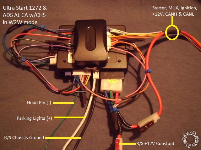
There will be only ten wires leaving the remote start / bypass assembly for connections
on the vehicle. Here is the wiring specific to the modules used :
U1272
6 Pin Ignition Harness
1 Yellow (+) Starter Output to vehicle 5 Pin ignition connector Starter (+) Pin 4 Pink/Dark Green
thru 5 Amp fuse and to ADS AL CA BLACK/ White Starter (+) Input
2 Green (+) Accessory Output not used
3 Red (+) +12V constant \ these 2 wires are combined into one and fused down
4 Red (+) +12V constant / to 20 Amps. Connect to +12V constant battery source.
5 White (+) Flex Relay Output not used
6 Blue (+) Ignition Output to ADS AL CA Pink Ignition wire and to ADS AL CA WHITE/ Red thru 1N4001 diode
2 Pin Harness
Black (-) Main Chassis Ground Chassis Ground
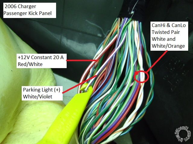
White Selectable Parking Light Output to vehicle WHITE/ Purple (+) Parking Light in PassKickPanel
*** set U1272 jumper to (+) Parking Light output
9 Pin Harness
1 Yellow (-) Rearm Output not Used
2 Brown (-) Disarm Output not used
3 Black (-) AUX1 Output not used
4 RED / White (-) Trunk Release to ADS AL CA RED / White Trunk (-) Input
5 WHITE/ Blue (-) Horn Output not used ( at customer request )
6 Pink (+) Brake Input to ADS AL CA Orange (+) Brake Output
7 GREEN / WHITE (-) Hood Pin Input to Hood Pin switch ( supplied in R/S kit )
8 Blue/White (AC) Tach Input to ADS AL CA PURPLE / White Tach ( AC ) Output
9 Blue (+/-) Glow Plug/WTS/Trigger Input not used
Lock Harness
Green (-) Lock to ADS AL CA GREEN/ Black Lock/Arm (-) Input
Blue (-) Unlock to ADS AL CA Blue/Black Unlock/Disarm (-) Input
3 Pin Bypass Harness
Red +12V to ADS AL CA Red +12V Input
Black Ground to ADS AL CA Black Ground Input
WHITE/ Violet (-) GWR to ADS AL CA Blue/White GWR (-) Input
ADS AL CA ( previous U1272 connections not listed )
7 Pin Connector
BROWN / Red CANH to vehicle WHITE/ Orange @ transponder connector Pin 6
BROWN / Yellow CANL to vehicle White @ transponder connector Pin 7
3 Pin White Connector
Yellow MUX to vehicle PURPLE / Brown MUX @ Ign connector Pin 2
3 Pin Blue Connector
White +12V to vehicle Light Blue/Red @ Ign connector Pin 5
WHITE/ Black Ignition (+) Output to vehicle Pink/White @ Ign connector Pin 3
Please download the ADS AL(DL) CH5 install guide for the detailed Type 1 wiring diagram at :
https://www.idatalink.com/support/get-install-guide/guide_id/9473
Disassembly :
The kick panel is a one piece assy and includes the door sill trim. Remove both driver & passenger side
by lifting the door sill ( 3 tabs ) and then lifting slightly and pulling straight back.
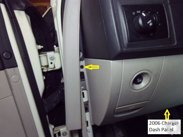
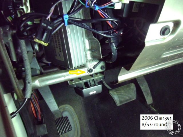
Remove the upper side dash trim piece shown to expose one lower dash panel retaining screw. Remove the other
lower dash panel retaining screw indicated with the yellow arrow, then pull the panel straight away from the
dash ( three clips along top edge ). Disconnect the Hood Release cable and trunk release harness. This will
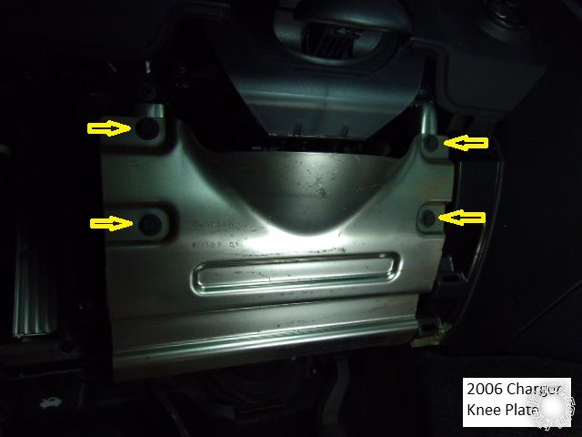
expose the knee brace which is held in place by the four 10mm bolts indicated.
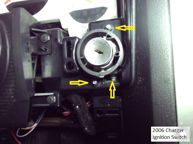
There is no need to remove the steering column covers but for better access to the ignition switch harnesses,
remove the instrument panel bezel. ( The main ignition harness is easy to reach but the transponder connector
is difficult.) There are 3 screws along the lower edge. Lower and fully extend the steering wheel, then gently
pull the ignition switch trim bezel out and then pull the instrument bezel away from the instrument cluster.
This will expose the ignition switch. The ignition switch is held in place by three 7mm nuts, shown below. The
nut at the bottom does not have to be removed, just loosened.
There is an insulation panel under the drivers dash ( not shown ) that is held in place by two fasteners along
the leading edge ( and the one dash panel screw removed earlier ) that is also removed during installation.
Installation :
There is plenty of room under the drivers dash for R/S placement. Aside from the Parking Light wire connection
in the PassKickPanel ( and possibly the R/S's +12V connection ) every thing is close and convenient. Here is a
picture of the R/S's chassis ground wire connection point.
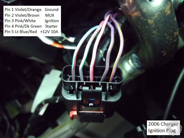
Here is a photo of the main ignition harness with the wires identified :
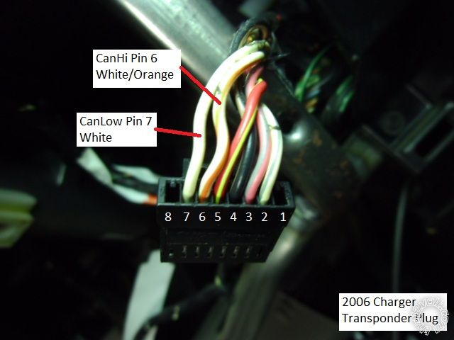
This is a shot of the transponder connector with the CAN wires indicated : ( Go by the pin location as the wire
colors can be different.)
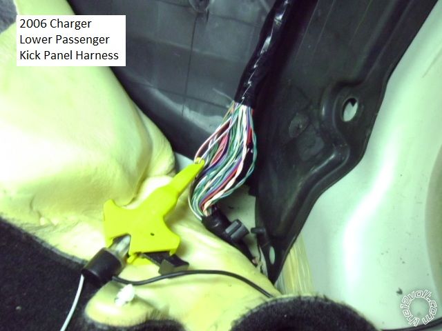
Roll back the carpeting in the passenger kick panel, as shown below, for better access to the wire harness :
Here is s picture of the Parking Light wire :
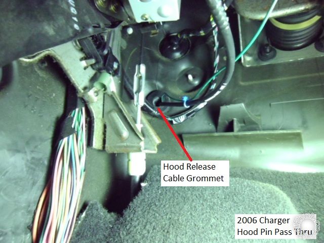
Firewall pass thru for the Hood Pin is available in several locations. The photo below shows the hood release
cable grommet under the drivers dash, in the left corner.
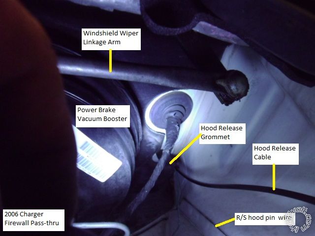
Remove the brake fluid reservoir panel cover in the engine compartment for better access to the hood release cable grommet
shown below :
As mentioned earlier, there are many bypass modules available for this vehicle. Going with a DATA style bypass
module will allow installation and programming with just one working key. Hardwiring the ignition connections
( solder, please! - no T-Taps or ScotchLocks ) in lieu of the T-Harness will save a few bucks.
-------------
Soldering is fun!
Replies:
Posted By: lucasoil4u
Date Posted: December 03, 2012 at 12:02 PM
Posted By: kreg357
Date Posted: December 03, 2012 at 2:19 PM
The Ultra Start U1272 is a very nice basic unit that is very reliable. It has some nice features, like
adjustable time Horn confirmation output, an antenna with bright blue LED's, a selectable Flex Ignition
relay, selectable polarity Parking Light output and very easy programming. There are some limitations,
with only two AUX outputs ( with limited programming options ), automatic transmission only, and limited
low current (-) ignition outputs. While it is a one-way AM system, the remote FOB's range is above average.
It has automatic Tach Learn and can accept the newer engines "weak" single spark plug coil signal.
For the customer looking for a reasonably priced system and the installer looking for no "come-backs"
( until they get a new vehicle ), it fits the bill. Think I've only had one DOA in the last year and that
was no horn output caught during install programming.
-------------
Soldering is fun!
Posted By: afridihamid
Date Posted: December 14, 2012 at 9:43 PM
A couple questions from a rookie.
I see the 5A fuse on the starter wire was called for by the idatalink unit's diagram.
But how do you know to fuse down the 12v wires to 20A? I understand in this car it's not the R/S unit that directly provides power to the starter so fusing down makes sense. Is there a rule of thumb for determining the fuse values typically?
Also, as the 12v constant in the ignition harness is only rated at 15A and not recommended for the power source, do you run your line straight to the battery or elsewhere with easier access?
Posted By: kreg357
Date Posted: December 15, 2012 at 6:03 AM
Good questions. As you noticed, the newer cars are handled differently from the older ones. The bypass
module manufacturers now supply an Installation guide that is more detailed than the earlier ones, too. The
guides now include most all of the wiring from the remote starter ( albeit a generic one ). It is best to follow
that guide exactly, hence the 5 Amp fuse added in the R/S's Starter output wire.
The aftermarket R/S unit is built to handle a wide variety of vehicles. Most vehicles still require ignition wire
connections that can draw as much as 30 Amps each, hence the thick wires and 30 Amp fuses. As you mentioned,
this Chrysler vehicle has thin, low current, ignition wires and a CAN Bus system and does not require high
current to control. One bypass manufacturer ( Fortin ) has an module for this vehicle ( EVO-ALL ) and their
diagram shows a 15 Amp fuse and power connection to the +12V constant wire at the vehicles ignition
harness. There is no firm rule of thumb for the exact fuse rating when making an install like this. The R/S brain
really doesn't draw much current itself. The high current demands are from the outputs it supplies. In this case,
the R/S was powering the ADS bypass module ( very low current draw & it was actually using the vehicles +12V
power from the ignition connector to supply its' IGN1 output ), the 5 Amp ( max ) Starter output and the (+) Parking
Light output. So, 5A for the Starter circuit, less than 10A for the Parking lights, an Amp for the bypass and another
Amp for the R/S's 4 internal relay coils during remote start, at most 20 Amps. Probably using a 15 Amp fuse would
have been sufficient. This fuse is really protecting the supply circuit in case of a catastrophic R/S failure. The U1272
has two +12V power wires, each rated at 30 Amps. Joining them together and just running one wire ( that can easily
carry 30 Amps ) to a +12V constant source makes things neater and easier.
I also agree with you about running any power wires a long distance and breaching a firewall to get to the vehicles
battery. While that is the best place to get +12V constant, it does present problems and add possible points of
failure ( heat, vibration, corrosion, etc ). Keeping your wires short & inside the passenger compartment makes sense
and I usually try to do that. A lot of vehicles have a fuse box inside the cabin, but not the newer Chrysler vehicles.
Finding a +12V constant wire that can be safely used is a challenge. I tested a bunch of wires in the Driver Kick
Panel a came up empty. Got lucky in the Passenger Kick Panel with the thick RED / White pictured. That is what I
used for the R/S power source. I believe this RED / White wire supplies power to the passenger power seat, which
this vehicle did not have.
For this install, I re-pinned the U1272 ignition harness during bench prep. I removed the Yellow Starter wire, the
Green Accessory wire and one of the Red +12V Input wires. I installed the Green wire in the connector in place of
the missing +12v Red wire and joined it with the remaining Red wire, fused down to 20 Amps. I installed the removed
Red wire into the connectors Starter output position and fused that down to 5 Amps for use as the Starter wire. This
got rid of unused wires and made good use of the two supplied fuse holders.
-------------
Soldering is fun!
Posted By: r82udy
Date Posted: March 19, 2013 at 12:14 AM
-------------
Quicklrner
Posted By: kreg357
Date Posted: March 19, 2013 at 7:42 AM
The 2006 Charger is this Pictorial is slightly different from your 2010 and would require different wiring.
There is a big learning curve involved with remote starters and the required bypass modules. Care
must be exercised when matching the remote starter to the bypass module and then to the vehicle.
Each one has it's own needs, strengths / weaknesses and peculiarities. Just learning which bypass
modules D2D communication mode works with a specific brand / model remote starter takes time.
Knowing things like if the factory FOB's will still work while the vehicle is remote started and if / how the
Factory Alarm can be controlled by aftermarket devices is important. The next big hurdle is obtaining
a bypass module that is loaded with the correct firmware for your vehicle. Companies like iDatalink
cater to 12 Volt professionals and restrict info and firmware access from non-professionals. Fortin
bypass modules come pre-loaded but XpressKit modules need to be flashed with a special USB cable
prior to use. Of course, there are on-line sellers that will load the module for you with your requested
firmware prior to shipment.
Your best bet is to decide which remote starter brand and model fits your needs. Things like range,
one or two-way communications and other features will be a factor in your choice. You will quickly
notice that the price goes up quickly. The remote starter and bypass used in this Pictorial could be
used for your 2010 Charger if the iDatalink bypass module was flashed with the ADS AL(DL) CH4
firmware ( instead of the CH5 firmware ). The parts used in this install can be found on-line for around
$110 dollars, flashed and delivered. There are other very good systems available. If cost is no object,
the Compustar CM6200 with the RF-1WG5-SS remote kit and the Fortin EVO-ALL with the optional
THAR-CHR4 harness would make for a quick and easy install. Cost would be around $230.
Here are some wire guide sources :
Here is a link to Bulldog Security : https://www.bulldogsecurity.com/bdnew/vehiclewiringdiagrams.asp
Here is a link to Ready Remote : https://www.readyremote.com/main.asp
Here is a link to AudioVox : https://techservices.audiovox.com/AccessRequest.aspx Sign-up & info is free.
-------------
Soldering is fun!