2003-2006 GMC Yukon Remote Start Pictorial
Printed From: the12volt.com
Forum Name: Car Security and Convenience - Alarm/Remote Start Pictorials
Forum Discription: Installer submitted Alarm, Keyless Entry, and Remote Start Pictorials from our Car Security and Convenience forum.
URL: https://www.the12volt.com/installbay/forum_posts.asp?tid=133000
Printed Date: April 30, 2026 at 2:51 PM
Topic: 2003-2006 GMC Yukon Remote Start Pictorial
Posted By: kreg357
Subject: 2003-2006 GMC Yukon Remote Start Pictorial
Date Posted: December 17, 2012 at 6:31 PM
This is a pictorial for a DIY remote start with keyless entry on a 2003 GMC Yukon. The 2003 - 2006 model
years are the same.
This is a popular vehicle and similar to many within GM. Other similar vehicles include the 2003 - 2006 Chevrolet Tahoe,
Chevrolet Silverado, Suburban & GMC Sierra, 2003 - 2004 Cadillac Escalade and some others.
There are many bypass modules available, from basic Passlock2 only to full featured modules. While the Passlock2 is
easy to bypass with the old, reliable, relays and resistor method, the power door locks make a full featured bypass module
very attractive. The bonus features like automatic heated seat and defroster activation make the choice easier. Popular
bypass choices for the DIY'er include the DEI GMDLBP, the Fortin EVO-ALL, INT-SL and INT-SL+ and from iDatalink the
ADS DLSL GM1. Each module has its' own strengths and weaknesses and, depending on the vehicles options, some are
more appropriate than others.
These vehicles do not have "one touch starting" but do have built in anti-grind. Some vehicles have the optional Factory
Alarm, heated seats, etc. Originally plan was to install a Compustar CM4200 and the DEI GMDLPB bypass module, shown
bench prepped below.
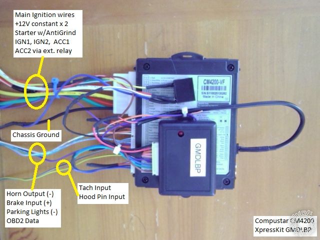
While this is a system is a solid performer, due to the bypass module it would not have handled this vehicles heated
accessories, so the customer opted for the upgrade system pictured below.
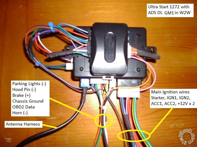
The ADS DL with GM1 firmware bypass module was chosen for this install. It handles the Passlock2, locks and Factory
Alarm ( if present ) and provides a Tach signal. Thru Data, it turns on the heated accessories during a remote start if the
engine temp is below 32 degrees. For Alarm installs, it also provides front door status trigger.
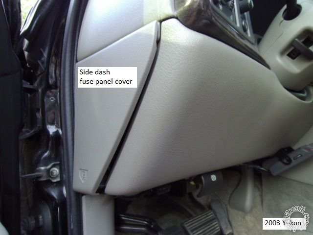
Disassembly :
Remove the side dash fuse box cover by pulling it out at the bottom edge. This will allow easy antenna harness routing
to the windshield.
Remove the two 7mm screws shown below and pull the lower dash panel straight away at the top. There are two clips
along the top edge.
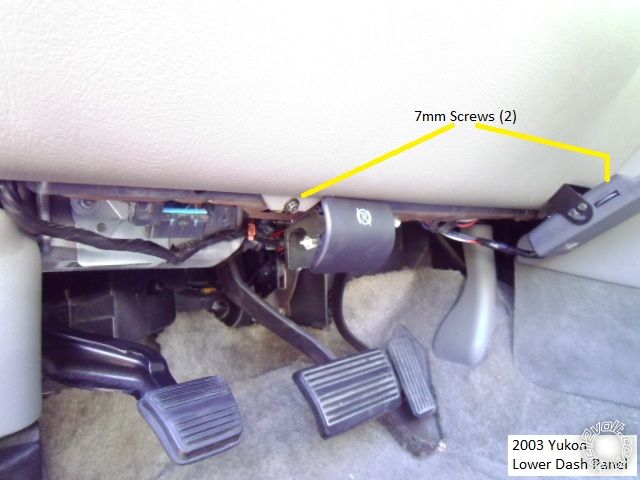
There is no need to remove the steering column cover. Remove the knee brace to expose the BCM and ignition harness
by removing the four 10mm nuts indicated.
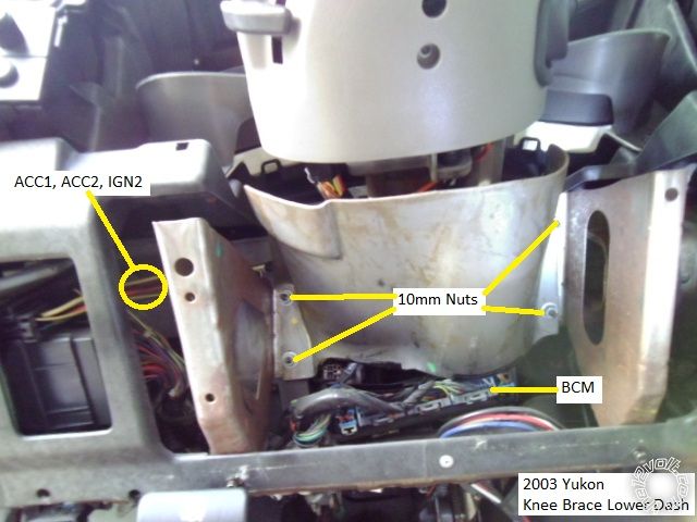
Here is a picture of the exposed wires after the knee brace is off.
Wiring :
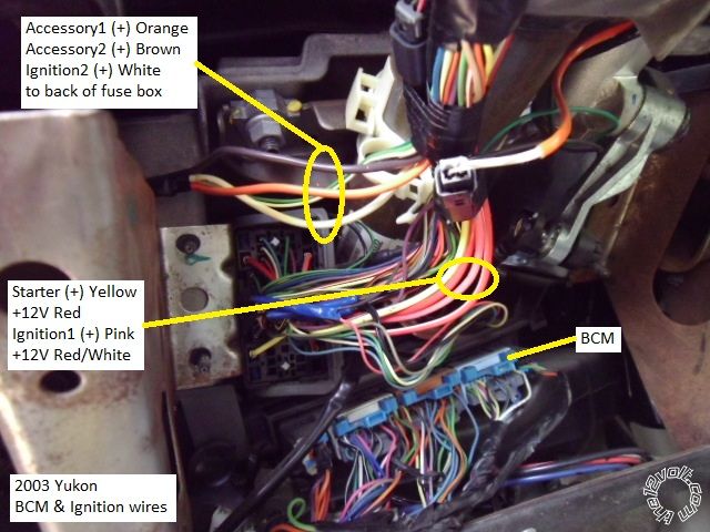
Below is a picture of the thick main ignition wires coming down from the steering column. Notice they split-up with 3 wires
going to the back of the fuse box. Plan the R/S wire routing to allow for the knee brace re-installation. Space is limited and
there is a real need for wire loom protection in this area to prevent wire chaffing against the metal knee plate. Please remember
to connect the White wire as IGN2 wire or error codes and transmission problems will occur.
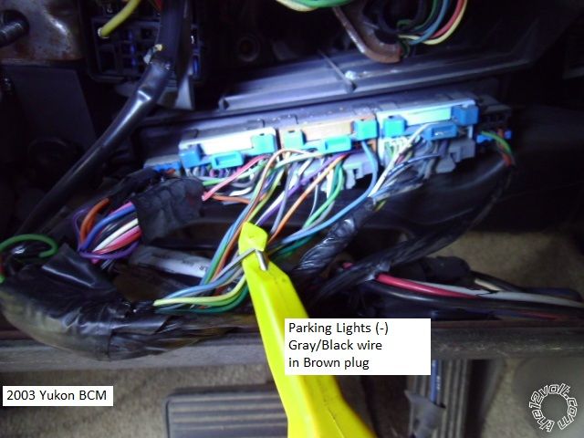
Here is a photo of the BCM with the Parking Light (-) wire marked. There is a (+) Parking Light wire, but why use it when the
(-) Parking Light wire is so convenient at the BCM. If installing an alarm system, the two rear door triggers are found in the
BCMs' Purple plug.
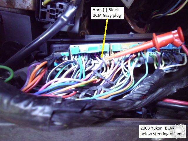
This is a shot of the ( optional ) Horn (-) wire at the BCM.
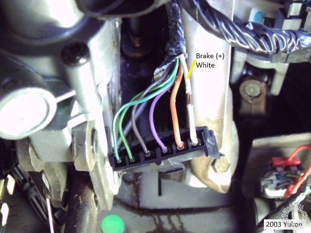
This is a picture of the Brake (+) in the brake pedal switch connector ( unplugged ). Please note that this brake switch moves
with the pedal and allowances should be made when routing, connecting and securing this R/S wire.
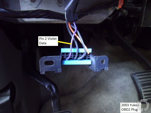
Here is a picture of the OBD2 diagnostic connector and its' Purple Data wire at Pin 2.
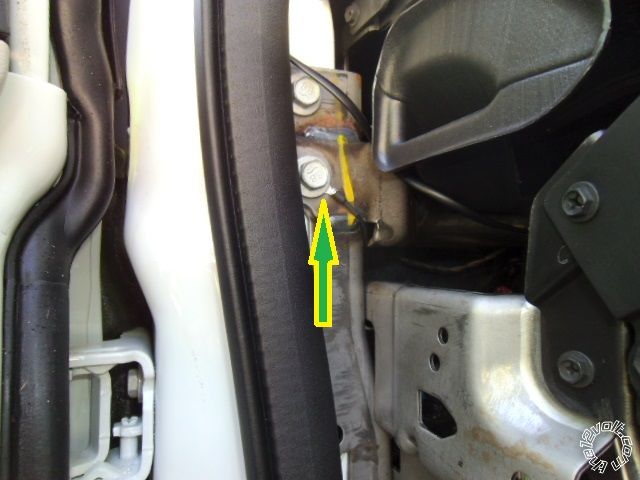
There are many locations to connect the R/S Chassis Ground wire under the dash. Firewall pass-thru for the Hood Pin is
found at the main wire harness behind the parking brake assy. As always, use a Digital Multi Meter to locate, test and verify
all vehicle wires prior to making a quality solder connection.
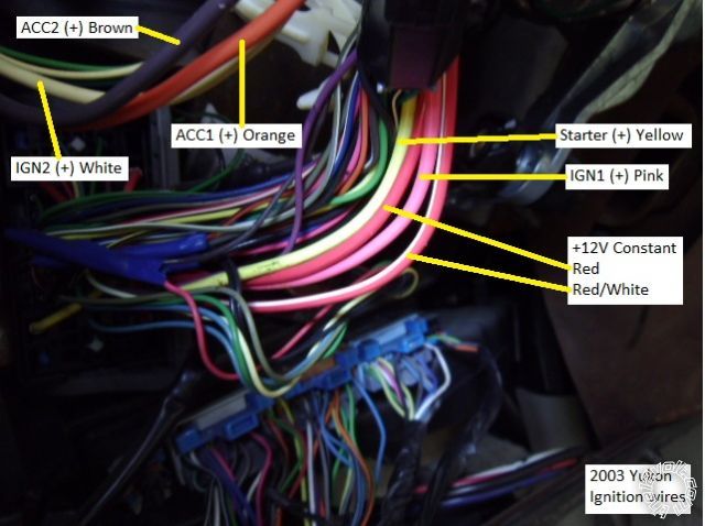
This style vehicle typifies many GM's from around this time period. With Passlock2, a convenient BCM under the steering
column and the GM standard ignition wire colors of : Red & RED / White for +12V constant, Yellow for Starter, Pink for IGN1
and White for IGN2, Orange for ACC1 and Brown for ACC2. ------------- Soldering is fun!
Replies:
Posted By: shortcircuit161
Date Posted: December 18, 2012 at 8:55 AM
Very nice!!! That's a very popular setup. Looks just like the Escalade and Silverado I did recently.
-------------
Posted By: jaimejr18
Date Posted: March 01, 2013 at 5:38 PM
how yu wire the locks and unlocj to work with the alarm
Posted By: kreg357
Date Posted: March 01, 2013 at 6:55 PM
"There are many bypass modules available, from basic Passlock2 only to full featured modules. While the Passlock2 is
easy to bypass with the old, reliable, relays and resistor method, the power door locks make a full featured bypass module
very attractive. The bonus features like automatic heated seat and defroster activation make the choice easier. Popular
bypass choices for the DIY'er include the DEI GMDLBP, the Fortin EVO-ALL, INT-SL and INT-SL+ and from iDatalink the
ADS DLSL GM1. Each module has its' own strengths and weaknesses and, depending on the vehicles options, some are
more appropriate than others."
The easy way is using a full featured bypass module like the ones mentioned above. ( The front doors are controlled by
a Data type signal, the rears are Type B.) Being as you need a bypass module for the Passlock2 ignition immobilizer
system, for a few extra dollars you can get a bypass module that will do the door locks, factory alarm, heated seats
and rear defroster and supply a Tach signal and front door pin status. For this install, all of this was handled by the
bypass modules one connection to the Violet wire at Pin 2 of the OBD2 connector.
Doing everything with relays would require going into both front doors and a total of 6 relays. Here is a link to DEI
Tech Tip 1601 : https://www.the12volt.com/installbay/file.asp?ID=828 And you would still need to bypass the
Passlock2 system.
Here is a link to a current, DIYer friendly, full featured bypass module, the Fortin EVO-ALL :
https://ifar.ca/download/7691/preview.html See Connection 3 for wiring details.
Please note that the EVO-ALL firmware version must be 4.06 or LOWER. ------------- Soldering is fun!
Posted By: racerjames76
Date Posted: March 06, 2013 at 9:39 AM
I have noticed ALOT of these full size GM vehicles coming back with the idatalink tach being dropped randomly. I have since begun running the tach to the white wire behind the intrument cluster on every install. Typically it is the only white wire back there, but I remember someone saying Pin A6. Do not recall if that is accurate...
-------------
To master and control electricity is perfection. *evil laugh*
Posted By: flobee4
Date Posted: March 06, 2013 at 8:45 PM
Just a heads up, be careful with those instrument clusters. It is VERY popular for the stepper motors that move the needles go bad. Definitely check the cluster during you pre-install checklist. I just replaced the 6 motors on my friends 04 Tahoe. Only the speedometer and gas were acting up, but I changed all of the motors anyway. The years affected are 02-06 Tahoe, Silverado, Yukon, Suburban... I also believe all years of the Envoy and Trailblazer too.
If they are bad and you're good at soldering, the whole job takes a half hour or so. There are alot of videos on YouTube on how to change them. A easy way to make some extra money.
Posted By: racerjames76
Date Posted: March 07, 2013 at 8:00 AM
Good tip there flobee, even if you can not repair it, it is a good idea to check to see if they are working so you do not get blamed for breaking them. Even though the problem is so common the parts and even entire ebay companies have sprung up to repair the issue since GM will not. At least not without charging you near $1000 for an entire new old stock gauge cluster (with the same problems mind you).
-------------
To master and control electricity is perfection. *evil laugh*
Posted By: r6ssrocket
Date Posted: November 04, 2013 at 7:48 AM
Great write-up! This has been very helpful for me in my first install. I have a question though - perhaps you can help. I have no idea where to hook in my lock controls! I hear the relay clicking (on remote start unit) when I press lock/unlock on remote... and GMDLBP is properly hooked to Astro-Start 903u unit but I don't know how to hook stater unit to the truck to control the locks... Any help is GREATLY appreciated. Thanks!
Posted By: r6ssrocket
Date Posted: November 04, 2013 at 7:49 AM
Forgot.. I have an 03 Silverado 2500 Duramax Diesel
Posted By: kreg357
Date Posted: November 04, 2013 at 9:18 AM
I am not familiar with your Astrostart 903U unit, but if it has the standard (-) Lock and Unlock outputs, they
would be connected to the GMDLBP's Green Lock and Blue Unlock wires. The GMDLBP uses these
commands from the 903U to generate signals on the Violet Data Output wire that is connected to the
trucks OBD2 connector at Pin 2. There are no direct connections of the 903U lock wires to the truck.
The relay clicking you hear when you press Lock or Unlock is probably the 903U's Parking Light relay.
-------------
Soldering is fun!
Posted By: r6ssrocket
Date Posted: November 04, 2013 at 7:05 PM
Thanks for responding! I have both the green and blue wires properly connected to their respective GMDLBP counterparts.. and the violet wire hooked to PIN #2 in OBDII port... Still no locks. This is really stumping me. I suppose it may be a programming error on my part? Are there any other common mistakes people make? Thanks again- your insight helped me build confidence in what I have accomplished so far!
Posted By: kreg357
Date Posted: November 05, 2013 at 8:21 AM
The GMDLBP has five different Platforms it can support. Your truck needs the Type 4 Platform. The GMDLBP install guide details how to change / set the Platform Type and program the module to the vehicle.
-------------
Soldering is fun!
Posted By: r6ssrocket
Date Posted: November 06, 2013 at 12:39 PM
Thank you! I figured it out- Thanks to you! GREATLY appreciated.
Posted By: r6ssrocket
Date Posted: November 07, 2013 at 4:58 AM
Ok I have to bug you one more time. Everything works.. most of the time. The locks will cycle once.. then won't work until they are cycled from inside the truck via the switch. Just not consistent.. not sure why. Thought you might have some insight... If not - Thank you for all your help so far!
Posted By: kreg357
Date Posted: November 07, 2013 at 1:22 PM
Not sure on that issue. I would double check all my connections. Make sure they are all well soldered and that the Chassis Ground connection is a soldered terminal ring to the chassis frame in a paint and rust free spot. Also re-seat all harness connectors on both the R/S and bypass module, plus any vehicle connectors you might have unplugged. Next would be a reset and re-program of the GMDLBP. After that would be some serious troubleshooting with a DMM to verify the R/S door lock outputs, etc.
-------------
Soldering is fun!
Posted By: r6ssrocket
Date Posted: November 07, 2013 at 6:15 PM
Good point on the ground... I have the ground wire loop sheet metal screwed to the flimsy metal behind the drivers side kick panel... not sure that is sufficient. Would that do it? I will find a better place.
Posted By: kreg357
Date Posted: November 07, 2013 at 10:23 PM
It is usually best to solder a terminal ring onto the R/S's ground wire and then find a convenient chassis frame bolt to make the connection.
Something like this :
------------- Soldering is fun!
Posted By: r6ssrocket
Date Posted: November 09, 2013 at 9:52 AM
Ok- so I grounded the unit to the chassis. No improvement. Frustrating. Again, I really appreciate your help though. It must be a programming issue or something I am over looking...
Posted By: dmonotjr
Date Posted: April 06, 2014 at 10:54 PM
i have used the write up as far as i can on my r/s install (2006 silverado crew cab with an ac delco 251d/dei 551t add on remote start system. but not im stumped on the last few connections where it says to connect to the oem keyless entry system. i cannot find a schematic that shows wiring for an input signal, rf signal, etc... im getting lost, ecspecially this being my first install attempt.
Posted By: kreg357
Date Posted: April 07, 2014 at 7:34 AM
This Pictorial was somewhat specific in the aftermarket R/S products used and to the vehicle and it's options. Your
chosen R/S system is the more basic "add-on" type. As such, it can only perform the remote start function, it does not
have any remote FOB's and can not perform any keyless entry functions. Basically it relies on the vehicles Factory
remote FOB's or another aftermarket alarm system for control / activation.
Being as this is your first R/S install, it would be advisable for you to create a new post in the Car Security and Convenience
section with all of your wiring ( to allow forum members to make any needed recommendations ) and your specific questions.
Also include additional info about your truck, like Factory RKE, etc. That being said, I see two areas of concern and will
venture a few guesses :
1. As mentioned, the 551t needs two things : A vehicle with power door locks and Factory Keyless Entry. Aftermarket
power locks and remote transmitters will work, too. Hopefully your truck already has this. Your 551t has an input,
H1/2 WHITE/ Blue (-) Activation Input, that will initiate a remote start if it see's one, two or three (-) trigger signals. Factory
default is one pulse, but it can be programmed for 2 or 3 pulses. This setting should be changed to either 2 or 3
because you don't want the truck to remote start every time you lock the doors... 
2. You didn't mention it, but your truck should have the Passlock2 engine immobilizer system. Unless you hacked the
BCM or did a resistor hard-bypass, you will need a bypass module. The 551t by itself, does not perform this function.
The remedy for #1 is programming the 551t Feature #9 to 3 pulses and an additional relay wired as below :
Relay Pin 85 and 87 to Chassis Ground
Relay Pin 86 to Lock Motor wire, Gray (except base models ** ) @ driver window switch, black 26 pin plug, pin 21
Relay Pin 30 to H1/2 WHITE/ Blue (-) Activation Input
Relay Pin 87a - not used
** On base models, it is Gray wire at the dash fuse box, black 12 pin plug, pin C ( but you still need Factory RKE FOB's)
I would add a coil quenching diode across the relays' coil, Pin 85 to Pin 86, to prevent any spike problems. Use a 1N4004 or
1N4007 with the band towards Pin 86. ( Thanks Howie II  ) )
The remedy for #2 is a bypass module. The basic, inexpensive, 556LW module will work, but there are many others
available. ------------- Soldering is fun!
Posted By: 1978malibu
Date Posted: February 11, 2015 at 2:08 PM
I have an autopage rs6rs665-2w. I attempted to hook factory horn up but it just a constant horn after I hit the unlick. Do I need a diode or relay
Posted By: racerjames76
Date Posted: February 11, 2015 at 2:50 PM
Did you by chance hook your domelight output to the trucks horn wire?  ------------- To master and control electricity is perfection. *evil laugh*
Posted By: kreg357
Date Posted: February 11, 2015 at 7:10 PM
Think RacerJames76 is on the right track.  The White wire is still at the default programming of Domelight. You need to program feature A6 to 2 chirps for the White wire to do the Horn Output function. ------------- Soldering is fun!
Posted By: elroro77
Date Posted: October 04, 2016 at 4:46 PM
Hi there I purchased a Compustar CS800-S & Idatalink ADS-ALCA Bypass Module × 1 flushed for my 2003 Yukon, can you help me with the wiring from diagram the compustar to the vehicle please?
Which wires go where?
Thanks
-------------
My name is Ro
Posted By: kreg357
Date Posted: October 04, 2016 at 6:58 PM
Good choices on the R/S and bypass module. Fairly easy install. Personally, I would go in W2W mode for a couple
of reasons. First there aren't a whole lot of inter-module connections to make. Secondly, the ADS with GM1 firmware
has been known to drop the Tach signal, so going W2W you can wire the CS800 Tach input directly to the vehicles
Tach wire at the instrument panel.
Here goes :
CM800-s
CN1
1 Red +12V Constant Red ( also goes to ADS AL-CA Red )
2 GREEN / WHITE + Parking Light Out Not Used
3 RED / White +12V Constant RED / White
4 White + Accessory Orange
5 Blue + Selectable set to IGN2 White
6 Yellow + Starter Yellow
7 Green + Ignition IGN1 Pink ( also goes to ADS AL-CA Pink )
8 Black Chassis Ground Chassis Ground ( also goes to ADS AL-CA Black )
CN2
1 GREEN / WHITE (-) Parking Lights GRAY/BLACK (-) BCM BROWN CONN, PIN B2
2 RED / Black (-) Starter Not Used
3 WHITE/ Black (-) Accessory To external relay - Pin 85
4 Black (-) Status To ADS AL-CA Blue/White GWR on 4 Pin plug
5 Orange (-) Rearm Not Used
6 ORANGE / White (-) Disarm To ADS AL-CA Brown on 10 Pin plug
7 White (-) Horn BLACK (-) STEERING COLUMN HARNESS OR BCM GRAY CONN, PIN B9
8 Gray/Black (-) Hood Pin To kit supplied and installed hood pin
9 Lt Blue/White (+) Brake WHITE (+) BRAKE PEDAL SWITCH
10 RED / White (-) Trigger Start Not Used
11 Red (+) Trigger Start Not Used
12 Yellow/Black Tach WHITE @ INSTRUMENT CLUSTER GRAY 24 PIN CONN, PIN A5
CN3
1 Empty
2 Violet/White (-) Trunk Release To ADS AL-CA RED / White on 10 Pin plug
3 ORANGE / Black (-) Driver Priority Unlock Not Used
4 Blue (-) Unlock To ADS AL-CA Blue/Black on 10 Pin plug
5 Blue/Black (-) Lock To ADS AL-CA GREEN/ Black on 10 Pin plug
6 Empty
ADS AL-CA w/ADS-AL(DL)-GM1 firmware ( wires not listed are not used )
4 Pin Power plug
Blue/White to CS800-s CN2 Pin 4 Black (-) Status
Black to CS800-s CN1 Pin 8 Black Chassis Ground
Red to CS800-s CN1 Pin 1 Red +12V constant
10 Pin Plug
GREEN/ BLACK to CS800-s CN3 Pin 5 Blue/Black
BLUE/BLACK to CS800-s CN3 Pin 4 Blue
RED / WHITE to CS800-s CN3 Pin 2 Violet/White
BROWN to CS800-s CN2 Pin 6 ORANGE / White
7 Pin Plug
Orange to Yukon OBD2 Pin 2 Violet
Pink to CS800-s CN1 Pin 7 Green
Extra external 30/40 Amp SPDT relay for the Yukons' ACC2 circuit :
Relay Pin 85 to CS800-s CN2 Pin 3 WHITE/ Black
Relay Pins 86 and 87 to Yukon +12V Constant RED / White @ ignition switch harness - Fuse at 25 Amps
Relay Pin 30 to Yukon Brown ACC2 wire @ ignition switch harness
You can make the inter-module connections on the bench prior to install using a soldering iron and heat
shrink tube. This will keep things neat and make for a very reliable system.
Remember to set the ADS AL-CA to Standard Mode and lock it in first before vehicle programming.
-------------
Soldering is fun!
Posted By: elroro77
Date Posted: October 05, 2016 at 11:07 AM
Hi Kreg357
Thank you so much for your immediate response, I plugged everything the way you mentioned above, but when I looked at the diagram they sent me (Type 3 installation) when I bought the R/S all those wire are not required to be connected to the CS800-s and according to this "diagram" all I needed to connect it was the the 4Pin power plug from the ADS AL-CA to the CS800-s, plus the orange to violet(Data) and the pink to the green from CS800-s.
Then I only plugged the hood pin, the brake pedal wire, parking lights, the horn and the Tach wire to the ADS-DL-GM1 yellow/blak(???) after that I programmed the ADS AL-CA to Data mode and everything works fine even the heated seats!! by the way my R/S is only 1 way communication not sure if I will have problem with the R/S in the future by wiring it this way??
One more thing; This extra external 30/40 Amp. is it required and if yes what is the function of it?
Once again thank you so much for all your help and information.
I look forward to hear form you soon.
-------------
My name is Ro
Posted By: kreg357
Date Posted: October 05, 2016 at 7:54 PM
You went in D2D mode between the modules. Should work OK as there isn't a whole lot of 2 way traffic. The CS800-s default is Tachless Mode so unless you changed that option and learned the Tach, the truck might have some issues starting when it gets really cold in Alberta. If you change the programming to Tach Mode and learn the Tach signal, you will be running from the ADS AL-CA's generated Tach signal that has been known to occasionally quit. As I mentioned, I usually go in W2W mode and connect to the trucks instrument panel tach signal for best reliability.
The extra external relay to power the trucks ACC2 circuit. Depending on the vehicle, it sometimes isn't necessary. Personally, I always make that connection just to duplicate everything a regular key start does. Just another of my quirks for ultimate reliability and no "come backs".
-------------
Soldering is fun!
Posted By: bandroidx
Date Posted: November 21, 2016 at 10:16 PM
I just wanted to thank the OP kreg357 for this incredible info that helped me immensely to install the remote start in my new to me 2004 Tahoe. The pictures with the wires pointed out were such a huge help and saved me a lot of time.
I went with a 2-way Viper and Idatalink ALCS and used D2D mode and it seems to be working well. (no issues so far with the tach coming from the Idatalink).
One question I had was regarding the ACC2 wire. Is there any info on what this actually does and what components use it? I decided not to hook it up, I could have easily added a relay but I saw it as potential for issues incase the relay were to fail. I installed the R/S the day after my friend finally tracked a really annoying battery drain issue to a 12v relay he had installed that had reversed polarity so that was fresh in my mind.
Without ACC2 engergized everything works fine including heated seats and heater blower, etc. No Check engine light, etc. I am just curious what it is that this wire does and just want to make 100% sure its ok I dont have it energized in my 2004 Tahoe Z71.
Thanks again.
Posted By: derrik86
Date Posted: November 26, 2016 at 11:08 PM
I installed the 5706 alarm using the GMdlbp in my 2006 crew cab Silverado diesel and now my dome lights ONLY work when I hit arm or disarm on the viper alarm.. should I wire my rear door triggers from the bcm to the viper directly ? or should they be wired to the GMDLBP module input then use that output to feed into the input of the viper ? and the factory horn is wired up. although the factory horn only goes off when the drivers front door is opened none of the other doors will set off the horn. it will set off the alarm though.. any help would be amazing its been a week and cant figure out the wiring right.. if It wasn't for this thread my remote start would still be throwing a error code. thank you very much !!
Posted By: prince504
Date Posted: December 12, 2016 at 7:39 PM
kreg357 wrote:
Good choices on the R/S and bypass module. Fairly easy install. Personally, I would go in W2W mode for a couple
of reasons. First there aren't a whole lot of inter-module connections to make. Secondly, the ADS with GM1 firmware
has been known to drop the Tach signal, so going W2W you can wire the CS800 Tach input directly to the vehicles
Tach wire at the instrument panel.
Extra external 30/40 Amp SPDT relay for the Yukons' ACC2 circuit :
Relay Pin 85 to CS800-s CN2 Pin 3 WHITE/ Black
Relay Pins 86 and 87 to Yukon +12V Constant RED / White @ ignition switch harness - Fuse at 25 Amps
Relay Pin 30 to Yukon Brown ACC2 wire @ ignition switch harness
You can make the inter-module connections on the bench prior to install using a soldering iron and heat
shrink tube. This will keep things neat and make for a very reliable system.
Remember to set the ADS AL-CA to Standard Mode and lock it in first before vehicle programming.
@kreg357 have you ever used the CM800 as a slave remote starter?
Posted By: kreg357
Date Posted: December 16, 2016 at 8:07 AM
@prince504
No, I have never used a CS800-s as a add-on R/S system. I have used the (-) and (+) Trigger Start input wires to test a system occasionally. An easy way to test a system if you're under the dash and don't have the remotes handy or a way to troubleshoot a possible antenna / remote problem and verify that the remote start function is still operational.
-------------
Soldering is fun!
Posted By: tyotteson
Date Posted: December 21, 2017 at 4:06 PM
Thank you for your detailed instructions. I was wondering if you might be able to provide details for my specific R/S system.
I purchased a MPC Remote Start & Keyless Entry (Manufacturer Part Number: 0770) for my 2005 Yukon. Is this a decent R/S system? I have never installed a R/S, but I am fairly technically inclined and it seems pretty easy, but I want to ensure there isn't anything I might not know that could cause me issues.
Thanks
Posted By: kreg357
Date Posted: December 21, 2017 at 6:04 PM
That system should be a piece of cake to install. If I'm looking at right one, it's basically
a Crimestopper RS4 system with the Fortin INT-SL bypass module, all pre-wired and ready to
go. I'm not a big fan of the T-Tap connections so I would cut them off and solder everything.
I would also go with a tilt switch as the hood pin to prevent rust and reduce issues if you live
in a northen area where they salt the roads during winter. Other than that, you should be good
to go.
As for the Crimestopper brand, I don't use them so I really don't have any reliability data on
them. We do have some forum members that use them, so perhaps they can chime in with info and
install insights for you.
-------------
Soldering is fun!
Posted By: motorsportsx
Date Posted: January 25, 2018 at 10:35 PM
Hey guys. Thanks for the pics but I'm still a bit confused on which power wires from my R/S go to constant vs switched.
I have a viper 5906v and a ADS-ALCA flashed with gm firmware in D2D mode.
The viper instructions ask for the following
2 - "red/black" - Fused 12v accesory/starter input
5 - "red" fused 12v ignition 1 input
9 - "red/white" fused 12v ignition 2 / flex relay input.
I'm not sure what starter input and flex relay input are listed for. Are all 3 of these just constant 12v? Or do the ignitions need to come on when the ignition is on?
Then in regards to ignition 2. There is an ignition 2 wire on the heavy guage harness and also on the 24 pin harness. Do i not need to use the 24 pin variant? (So i would use the pink and pink/white On the heavy guage harness for ignition 1 and 2)
Any help is greatly appreciated.
Posted By: kreg357
Date Posted: January 26, 2018 at 3:19 AM
There are four +12V input power wires on your Viper 5906V. There is a Red wire in the H1 plug and the H3 plug has
Red, Red/Black and Red/White wires, all with fuses. There are two +12V power wires in the truck, Red and Red/White
as shown on Page 1, that you connect these Viper wires to. Split the load between them, 2 Vipers wires to each.
If you look closely at the Viper install guide, the wires are usually marked with their polarity. Specifically, the
PINK (-) 200mA IGNITION 1 OUTPUT on the 24 pin connector is marked as a (-) output and would have a disastrous
affect on the Viper if connected to the vehicles thick Pink +12V Ignition1 or thick White Ignition2 wire. Those thin
(-) 200mA ignition output wires are typically used to control external relays. You would use the (-) 200mA Accessory
Output wire to control an external relay if you wished to power the trucks Brown ACC2 wire. I would suggest making a
wire connection list / chart of your Viper system to vehicle wires and posting it for member review and input prior
to install.
-------------
Soldering is fun!
Posted By: motorsportsx
Date Posted: January 26, 2018 at 7:42 PM
This is very helpful, thanks. So I will connect the 2 viper reds to the truck reds. And the 2 viper red/white to the truck red whites.
I will post my complete setup later this weekend for review. Thanks very much for the help. I was thinking id need to run powers out to the battery. Lol. By the way..just Curious.. is a t-harness worth buying? Does it make all the taps for you
Posted By: kreg357
Date Posted: January 27, 2018 at 6:49 AM
I don't believe there is a T-Harness available for this vehicle that can make all the necessary connections.
There are many connectors involved from ignition wires to door locks, horn, alarm, brakes, OBD2 and parking
lights that would be needed. Most all of the wires are easily accessible so removing some insulation and
making the manual, soldered connections isn't too difficult.
-------------
Soldering is fun!
Posted By: motorsportsx
Date Posted: January 28, 2018 at 7:57 PM
Ok. How the heck do i get this thing in auto transmission Mode? Lolevrything is working but remote start. 7 flashes.
Posted By: kreg357
Date Posted: January 29, 2018 at 7:06 AM
You must change a program menu option. See Menu 3, Item 1. Set it to Option 2 for a
vehicle with automatic transmission. The procedure is detailed on Page 2 of this guide :
https://www.the12volt.com/installbay/file.asp?ID=1375
-------------
Soldering is fun!
Posted By: wmellott
Date Posted: December 01, 2018 at 11:05 AM
Question as this has now been stumping me on/off for 2 weeks
2003 Suburban
RS - PS01-G5 originally with Idatalink ADS-TBSL-PL (we had used the 3 wire connection, Red, Blk, Blue/Wht to PS01-G5 Y/Blk)
We could not get the ADS-TBSL-PL to program - so ultimately we figured NG out of box
so we replaced it with the ADS-ALCA currently using the data cable (instead of the 3 wire) + Orange to ODB2 and Pink to Ign Pink
Same issue I can not get the ALCA to program - just goes red
I am fairly certain data at the OBD2 port on Purple is good - as my only way to test is via my ODB2 scanner which is reading data
Any ideas
Thanks
Bill
Posted By: kreg357
Date Posted: December 02, 2018 at 7:53 PM
I am not familiar with the R/S system you are using. I think it is a one button Crimestopper system?
Going by the G5 install guide, it looks like the default for the data port is ADS iDatalink. You
should be OK going in D2D mode but making the hardwire connections and going W2W is
fine. Either way, you must choose and set the bypass modules Installation Mode prior to
doing the vehicle programming. This is shown at the top of Page 17 of 19 in the ADS TBSL PL
install guide. Think I would go back to that bypass module, connect in W2W mode ( your
wiring looks good ) and try again. When you select the Installation Mode ( two blinks ) and
lock it in, you are also doing a Factory Reset on the bypass module. Remember to connect
the ADS TBSL PL Pink wire to the G5's thick Pink wire that connects to the trucks Pink
IGN1 wire. Also, the ADS TBSL PL will only handle the Passlock2 bypass function and
nothing else. With your one button system, you will not be able to unlock the doors while
the R/S is going unless you do some serious relay work.
With the ADS AL CA, did you Flash it with the correct firmware? Think they come with CH4
pre-installed and you need ADS-AL(DL)-GM1 firmware. This is a full featured firmware and will
do many other things besides the Passlock2 bypass.
-------------
Soldering is fun!
Posted By: wmellott
Date Posted: December 02, 2018 at 9:03 PM
Thanks, I agree the ALCA is the better way to go and using the data/dbi cable to the PS01-G5
I haven't flashed the ALCA, have it just came from the folks I purchased it from.
It seems odd that neither the TBSL-PL or the ALCA will sync tot he data stream on the Purple OBD2 j1850 wire.
Could this be because either unit is not "flashed" ?
Thanks
Bill
Posted By: kreg357
Date Posted: December 03, 2018 at 7:00 AM
The ADS TBSL PL comes pre-flashed with the correct firmware and should be ready
to go right out of the box. I would try it again after double checking all the
connections and start off with a Factory reset, Installation Mode selection and
then vehicle programming with the key.
The ADS AL-CA is good upgrade considering all the extras you get but will need
to flashed using the ADS USB cable with the correct firmware before it will
program to the truck with the key.
-------------
Soldering is fun!
Posted By: drewboy455
Date Posted: December 30, 2018 at 9:16 AM
I also have a Compustar CS800-S & Idatalink ADS-ALCA Bypass Module installing in a 2003 Suburban. I have tried both D2D and W2W, I've tried the white tach wire behind the instrument cluster, and injector wire, and a coil wire, and the thing still starts and shuts off right away. Also the door locks are not working. The module is clicking with the parking light flashes, but no door lock or unlock. I'm not sure where to go next. Any help would be greatly appreciated!!!
Posted By: geepherder
Date Posted: December 30, 2018 at 10:18 AM
Did you learn the tach?
-------------
My ex once told me I have a perfect face for radio.
Posted By: drewboy455
Date Posted: December 30, 2018 at 10:31 AM
Yes, I did the tach learn procedure and got 1 parking light flash. The ALCA bypass manual says to set to standard hardwire mode and press the hold the button til the light stays solid green. It turns solid green then turns to flashing red. The manual says it is not programmed correctly. Do I need to have the bypass module flashed? when I ordered it it said it was ready to install for my Suburban.
Posted By: drewboy455
Date Posted: December 30, 2018 at 11:45 AM
Kreg357 said...
Extra external 30/40 Amp SPDT relay for the Yukons' ACC2 circuit :
Relay Pin 85 to CS800-s CN2 Pin 3 WHITE/ Black
Relay Pins 86 and 87 to Yukon +12V Constant RED / White @ ignition switch harness - Fuse at 25 Amps
Relay Pin 30 to Yukon Brown ACC2 wire @ ignition switch harness
Is this a relay already on the truck or something I need to add?
Also how do I program the cs800-s to the tach sensing mode? the firstech book gives a table with the menu options but it isn't very clear on how to do it. I need to program option 2.04 setting #2 for tach sensing.
Posted By: geepherder
Date Posted: December 30, 2018 at 2:39 PM
It may need to be flashed. Unlike DEI, I believe idatalink allows you to flash your own stuff. You just need the right cable. I've never done this, so I wouldn't know what is required.
You need to add that relay.
I couldn't make sense of the manual, but see if this helps:
https://www.youtube.com/watch?v=gBHGGpkVYEU------------- My ex once told me I have a perfect face for radio.
Posted By: kreg357
Date Posted: December 31, 2018 at 6:54 PM
drewboy455 wrote:
I also have a Compustar CS800-S & Idatalink ADS-ALCA Bypass Module installing in a 2003 Suburban. I have tried both D2D and W2W, I've tried the white tach wire behind the instrument cluster, and injector wire, and a coil wire, and the thing still starts and shuts off right away. Also the door locks are not working. The module is clicking with the parking light flashes, but no door lock or unlock. I'm not sure where to go next. Any help would be greatly appreciated!!!
The ADS AL-CA bypass module comes from the factory flashed with CH4 firmware. It needs to be flashed with the ADS-AL(DL)-GM1
firmware for your application. If the seller did indeed flash it with the correct firmware, you should be all set. However,
there is no way to tell without actually trying it. The blinking red LED leads me to believe that you still have the CH4
firmware assuming you set the install mode properly and then failed to have successful vehicle programming results.
You would need the ADS USB cable and iDatalink approved access to check and flash your bypass module. ------------- Soldering is fun!
|