1995 Ford Windstar Remote Start w/Keyless Entry Pictorial
Older minivan with previous Valet after-market alarm install. Previous owner pulled the connectors off the
Valet controller ( you can see them hanging down past the under-dash fuse box ). The 1995 and 1996 models
are the same. No ignition immobilizer system. Early production vehicles might have 5 Wire Rev door locks
but later models and all with factory remote keyless entry have Type B (-) locks. This minivan does not have
built in Anti-Grind or "One-Touch-Start". Tach Mode remote start operation is recommended.
Disassembly :
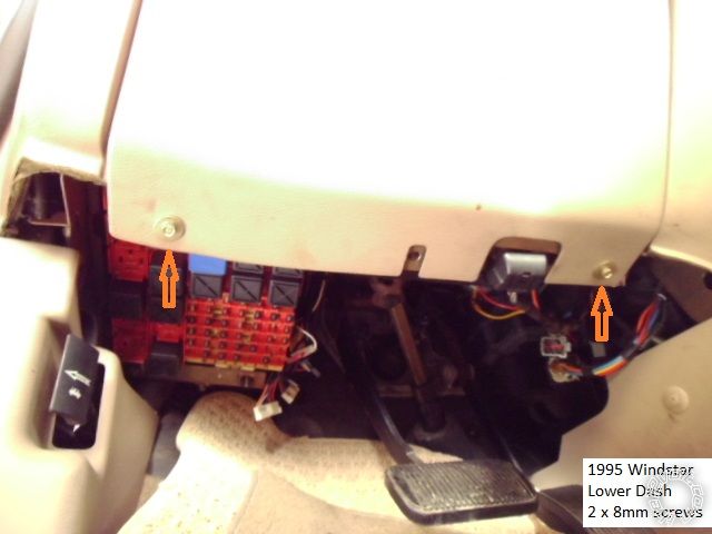
Remove the lower dash panel by removing two 8mm screws indicated below. Pull the panel straight away
at the top edge ( two plastic clips ).
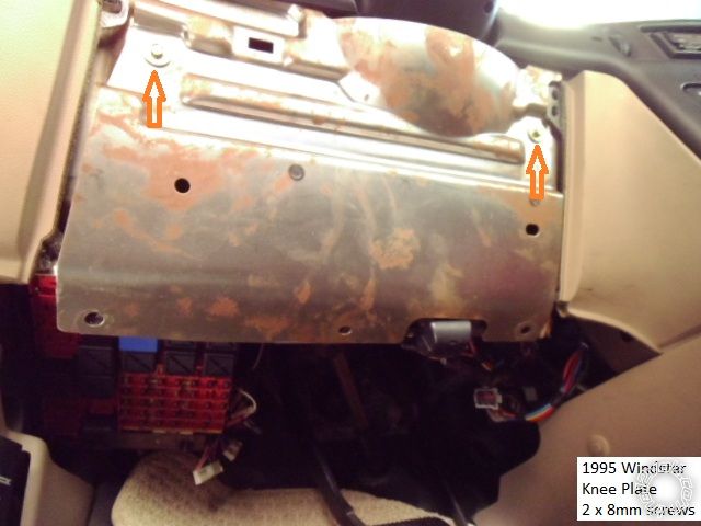
Remove the metal knee plate by removing the two indicated 8mm screws shown below.
Not shown is another metal plate mounted to the underside of the steering column. It is held in place
with four 13mm nuts. A deep socket will be required due to the length of the studs. This will expose the
main ignition connector and all necessary wire harnesses.
The Driver Kick Panel is retained with one clip and two plastic guides. Lift the leading edge of the door sill
and pull the DKP back and away.
Wiring :
Please note that a Digital Multi Meter is recommended for wire testing. The "Computer Safe Test LED Light"
used in this pictorial was safe to use on all wires ( Red LED = +12V and Green LED = chassis ground ) except
the tach signal.
Below is a photo of the main ignition connector ( disconnected ) and all necessary wire marked. It is held in
place by one 7mm screw.
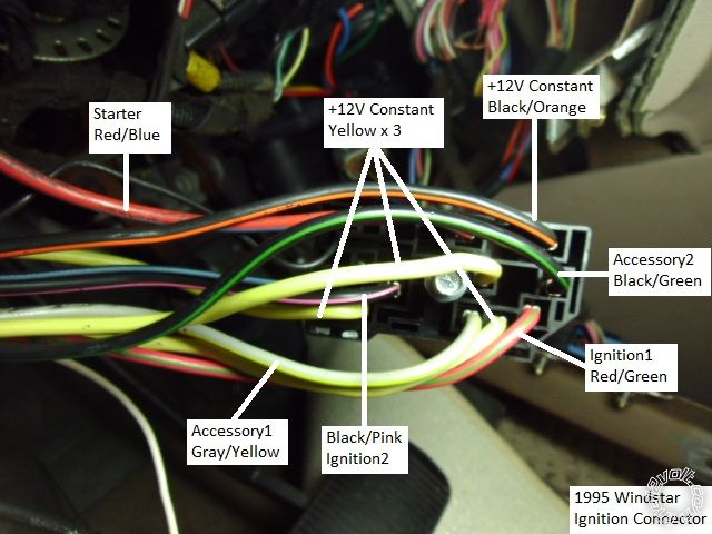
Some notes on the ignition wires. All are thick ( 10 or 12 Ga ) wires. There are plenty of +12V constant sources
( 4 ). This vehicle had a RED / Blue Starter wire but it can also be WHITE/ Pink. I powered the wires as marked but
there is conflicting info on all the available wire guides. My testing found only one Starter wire, one Ignition wire
( RED / Green ) and three Accessory wires ( Gray / YELLOW, BLACK/ Pink and BLACK/ Green ). Connected as shown did
not cause any CEL's and all Heat A/C functions worked properly under remote start.
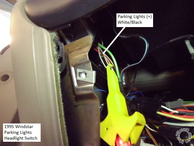
This is a picture of the (+) Parking Light wire found in the group of wires leaving the back of the Headlight switch.
There are two WHITE/ Black wires. The correct wire shown is marginally thicker but test to verify.
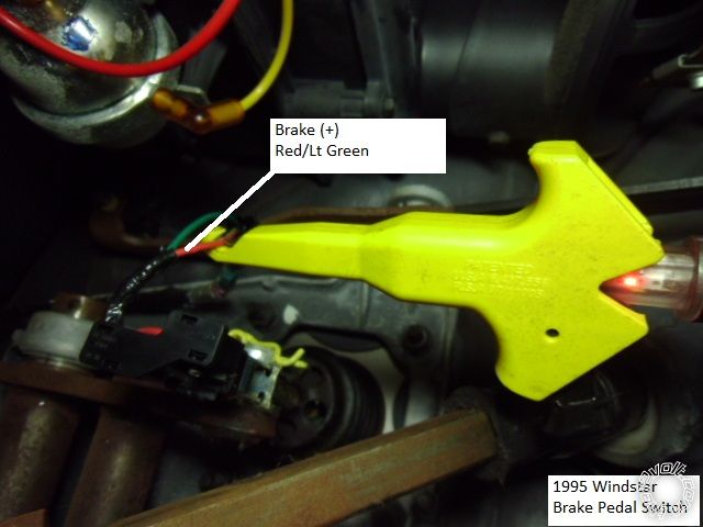
This is a photo of the (+) Brake wire found at the switch ( two wires ) at the top of the brake pedal. ( Sorry for the
poor lighting.)
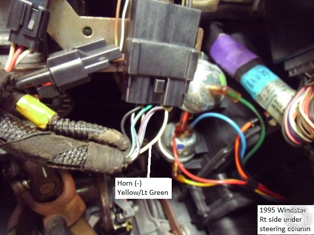
Here is a picture of the (-) Horn wire. ( Sorry for the washed out colors...)
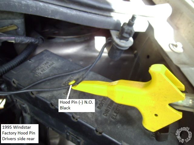
This vehicle had a factory hood pin installed. It is located drivers side, rear corner and is the correct N.O. (-) output
type. Photo below :
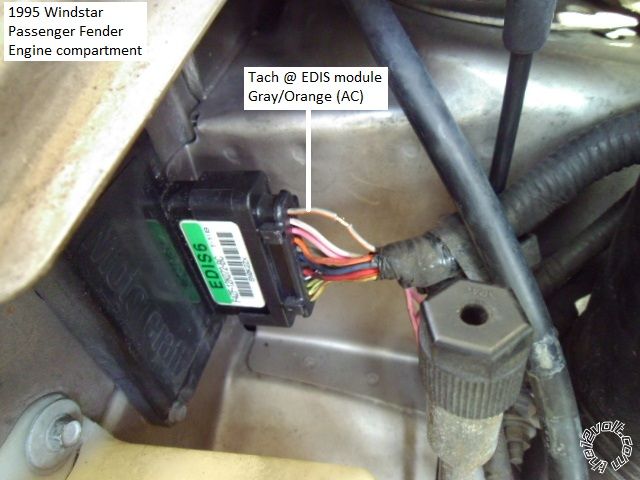
Here is a picture of a good tach signal source. The EDIS module is mounted on the passenger fender wall. It has
a removable harness cover ( slide it up and off ).
Firewall pass thru for both the above wires is a cable grommet just above the carpet and to the left of the brake pedal
area.
Not shown are the door lock wires ( camera issues  ). This vehicle did not have Factory Keyless Entry but the locks
were Type B (-). Lock wire was Pink / YELLOW and Unlock was Pink/Light Green. Both are found in the driver kick
panel area. The rear hatch locked and unlocked with the other doors.
-------------
Soldering is fun!
Just out of curiosity, what are you using as a probe for the wires in this pictorial? I've never seen one of those.
-------------
I drink current, eat ohms, and bleed voltage
It's called a Circuit Buddy. Only draws 3mA @12V DC. Very handy plastic ( non-conductive ) grip that allows one-handed operation to clip on to suspect wire.
Here is a link for more info : https://www.circuitbuddy.net/
-------------
Soldering is fun!
Sorry to derail, but how does that Circuit Buddy work on tach/data wires? I use a Waekon 76200 pistol probe that has 3 small led's that chase for data circuits. Curious how this thing compares.

-------------
To master and control electricity is perfection. *evil laugh*
Truthfully, I haven't used it on a Tach wire. Kinda afraid if it's a delicate ECM output. I generally use a Fluke DMM set to AC or if I'm in the shop, a Tektronix 465 O'scope. Think your Waekon probe is much more sophisticated than the Circuit Buddy.
The other issue is that the Circuit Buddy can only show one signal ( either + or - ) at a time. It has only one wire that you clip onto a +12V constant or chassis ground depending on what type signal you are looking for, then you probe the suspect wire. It's great for quick / simple checks, and the one handed hook and pierce is brilliant, but it does have some limitations.
-------------
Soldering is fun!