This is a pictorial for a remote start with keyless entry system install on a 2007 Honda CR-V. The 2008 model is the same.
The vehicle is a standard LX model with automatic transmission. The LX model does not have a Factory Alarm system. As
with all Honda's, the factory keyless entry system is disabled while the engine is running, so a remote start with keyless
entry is recommended. This vehicle does not have "one-touch" starting so Tach Mode remote start operation is a good
idea. The trunk unlocks with the other 4 doors. Additionally, there is no built-in anti-grind so this might be a good option
to add with the remote starter.
There are many good transponder bypass modules available for this vehicle. Since all of the wires are convenient and available,
a basic bypass module like the XpressKit PKALL, iDatalink ADS TBSL-KO, Fortin Key-Override-All or Honda SL3 are good choices.
If cost is a major consideration, the PKH34 is a reliable and less expensive alternative ( used for this install ).
This system I installed over 5 years ago and these pictures were taken during system un-install, prior to dealer trade-in.
Disassembly :
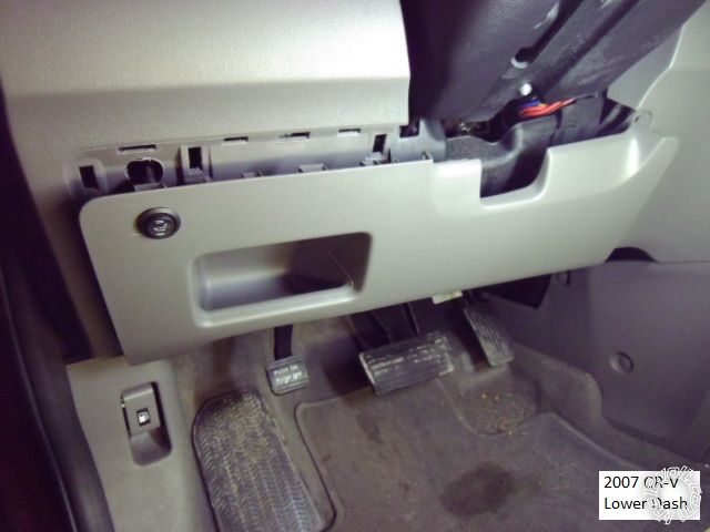
Remove the lower dash panel by pulling it straight away at the bottom and then at the top. There are no screw fasteners used,
just plastic snaps. ( The heated seat control is non-factory. )
Remove the lower steering column cover by removing the 3 screws indicated ( Yellow's are the same while the Red one is a
machine screw.)
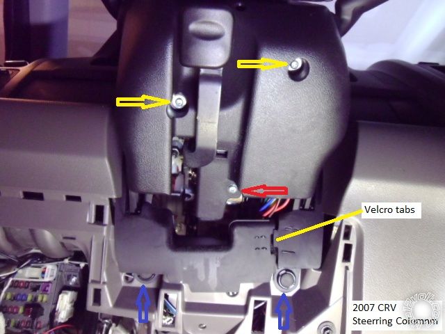
Gently squeze at the seems of the upper and lower halves to seperate and remove the steering column covers. The rubber
shield can be opened for better access by separating the two sections at the Velcro split and removing the two poppers
indicated with blue arrows.
Wiring :
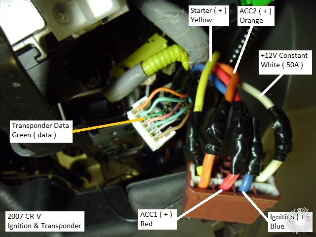
This is a picture of the main ignition and transponder connectors found at the ignition switch at the right side of the column.
Space is tight and wiring allowances should be made for the tilt / telescopic movements of the steering column.
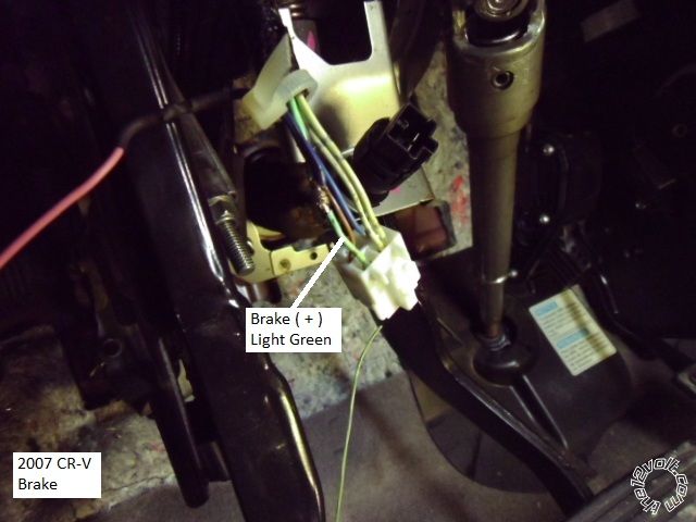
This is a photo of the brake wire ( connector removed from pedal switch in background ).
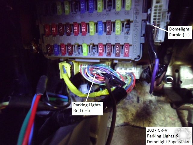
Here is a picture of the (+) parking light wire at the bottom middle connector on fuse box. Also shown is the Domelight
supervision wire. There is also a (-) Parking Light wire available at the headlight switch, not pictured.
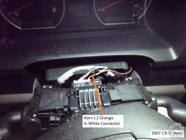
This is a shot of the horn wire.
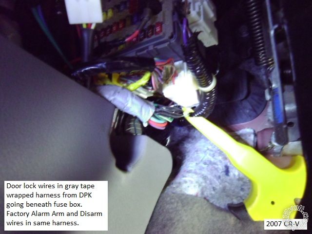
This is a photo of the door lock wire location.
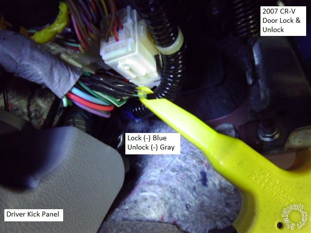
This is a close-up the lock wires.
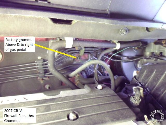
Firewall pass-thru for the tach and hood pin wires is found above the gas pedal, as shown below.
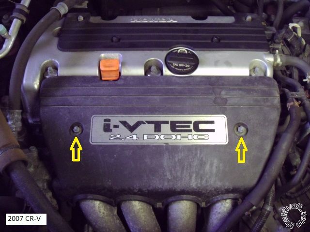
The F.I.'s are located below this engine cover. Remove the two 10mm nuts indicated and lift the cover off.
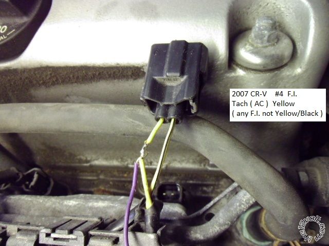
This is a picture of the F.I. tach signal wire ( connector removed ).
Please note that a properly soldered and insulated wire connection still works & shines after 5 years. That won't be the
case for a T-Tap or ScotchLok connection.
-------------
Soldering is fun!
Nice to see you using 33+ on those joints, just a thought remove (one at a time of course) those ignition connectors and slide some 9 mm (3/8") sleeving over the solder joints. I was doing a Nissan yesterday with a similar plug and the thought occurred to me.
Great minds, amazing how your injector wiring is identical to mine.....
-------------
Amateurs assume, don't test and have problems; pros test first. I am not a free install service.
Read the installation manual, do a search here or online for your vehicle wiring before posting.
Excellent idea. I wasn't sure if the 3/8" diameter heat shrink tube would make it over the de-pinned Honda spade terminal lug and still shrink enough to make a tight fit but with a wrap or two or Scotch Super 33+ first, it would work.

-------------
Soldering is fun!
I was too lazy to do it yesterday

-------------
Amateurs assume, don't test and have problems; pros test first. I am not a free install service.
Read the installation manual, do a search here or online for your vehicle wiring before posting.
De-pinning the vehicles connectors can be time consuming and risky.
-------------
Soldering is fun!
Yes but not at our level of competence, agree though about time consuming, it's why I didn't do it.
Let's face it, on my car, everything not soldered I'm using (expensive) Amp Sureseal and convoluted tubing under the hood. Would you do that for a customer with time and budget constraints?
-------------
Amateurs assume, don't test and have problems; pros test first. I am not a free install service.
Read the installation manual, do a search here or online for your vehicle wiring before posting.
Split loom tube, mercury tilt switches and soldered connections are standard. Haven't had any requests for more but if the price is right...
-------------
Soldering is fun!
I always keep to a certain standard, you don't want to be sl*gged off by the next techie who gets into that car.Fabric tape inside, especially on Euro cars, in fact Saturday's customer who works in electronics noticed me using it and was most pleased.
-------------
Amateurs assume, don't test and have problems; pros test first. I am not a free install service.
Read the installation manual, do a search here or online for your vehicle wiring before posting.
This has been very helpful for me. The only thing I'm stuck on is the door lock wires. Your picture shows blue and gray wires (which the DBALL2 manual agrees with) but I don't know if it is light blue or dark blue. There are dark blue and gray wires with silver marks on them (which I connected to without success. My tester registered change when I locked and unlocked) and there are smaller light blue and gray wires too.
Any chance anyone knows which wires it should be? Were they the really small wires or the larger?
Aaron
They are very thin gauge ( and fragile ). Always test and locate all wires with a DMM ( or very computer safe test LED ). PM sent.
-------------
Soldering is fun!