DIY pictorial for the 2002 F250 Super Duty. The 2002 thru 2005 model years for the F250 and F350 should be the same.
There are some variations that will require different installation procedures. The three major variations are Gas / Diesel
engines, Transponder based Ignition Immobilizer system ( PATS ) and Factory Keyless Entry. This pictorial shows a standard
remote start with keyless entry install on a truck with the 5.4 liter Triton V-8, no PATS immobilizer and no Factory Keyless
Entry.
There are many quality R/S w/Keyless entry systems available and the choice is usually subjective. This is a parts list for
this install :
Ultra Start U1272 R/S w/keyless entry
Directed 451M door lock module
30/40 Amp SPDT relay w/5 wire harness ( for ACC2 or IGN2 )
In-line fuse holder w/30 Amp fuse
1N4004 diode ( relay coil quenching )
and the usual solder, Scotch Super 33+ tape, heat shink tube, tie wraps and terminal lugs.
Disassembly :
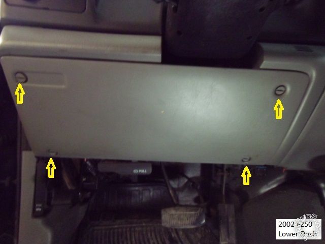
Remove the drivers lower dash panel by turning the four indicated fasteners 1/4 turn.
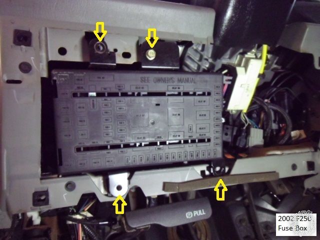
There was no need to remove the steering column covers because this truck did not have the PATS immobilizer. For
better access to the main ignition connector, remove the four 10mm bolts shown and gently pull the fuse box assy away
from the dash.
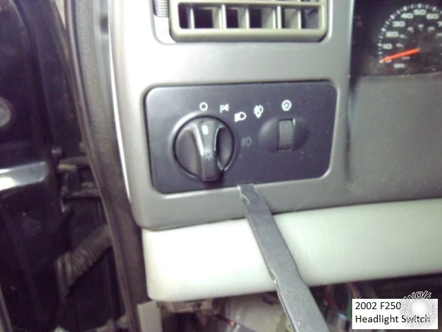
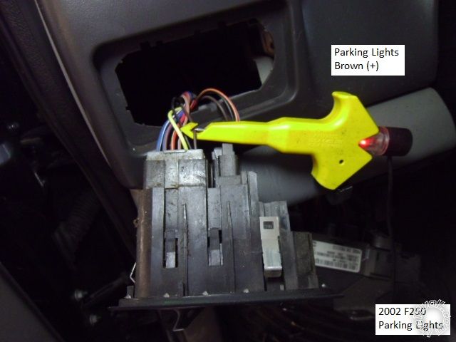
Remove the Headlight Switch panel by using a non-marring trim tool to pry out from the bottom as pictured below.
One of the variations mentioned above was the Factory Keyless option. Trucks with Factory keyless entry have a VSM
module and Type B (-) locks. These trucks might also require additional wiring for GEM wake-up and Brake / Starter wire
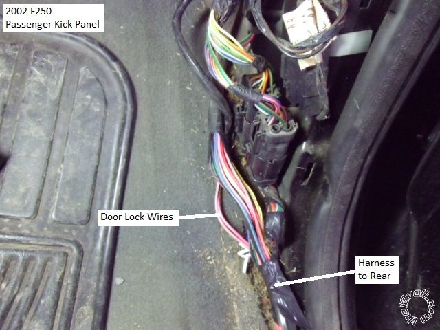
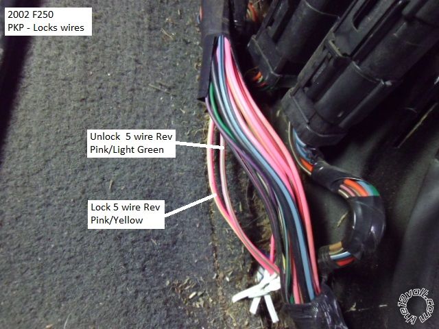
isolation so plan accordingly. This trunk did not come with Factory Keyless Entry and had the Type C ( 5 wire REV ) locks.
The lock wires can be found in either kick panel. The drivers kick panel is partially blocked by the parking brake ( and ten
year old cold plastic is fragile ) so I chose to access the lock wires in the passenger kick panel. Lift the door sill trim at
the front edge, remove the one plastic retainer and pull the PKP back any away ( no photo ).
Wiring :
This is a picture of the PKP and the door locks wires. Locate the wires using a Digital Multi Meter ( or computer safe test
light ) by testing for a (+) pulse when the lock or unlock button in the DRIVERS door switch is pressed.
Once the lock and unlock wires are identified, cut them in an easily accessible place, then use the DMM to identify which side
of the cut wire shows ground. Follow the 451M Type C install directions to make your soldered connections. Close up
of the lock wires below.
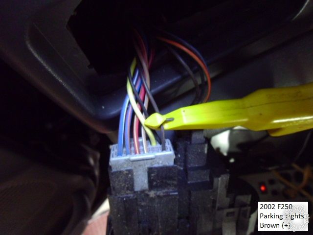
Below are photos of the Parking Light wire ( Headlight Switch Panel removed earlier ).
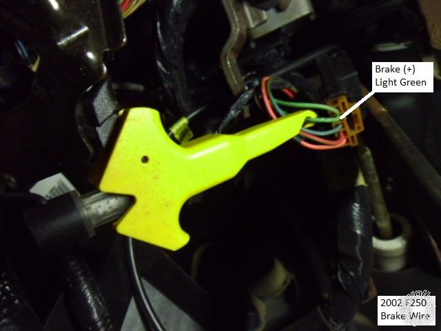
This is a shot of the Brake wire at the switch at the top of the brake pedal.
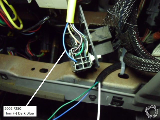
Here is a picture of the horn wire. Big warning! Ford has the bad habit of including the horn wire in the Yellow sleeved
Air Bag Harness. Improper wire testing will deploy the air bag. Do not separate this connector and only test this wire
with a Digital Multi Meter.
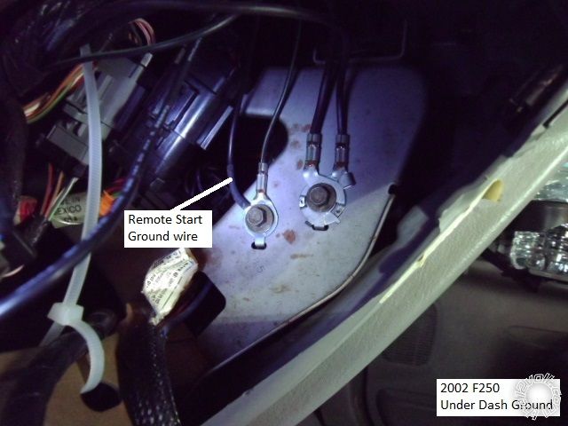
This is picture of a convenient ground connection point on the drivers side of the heater control / radio area. Remember
to use a soldered on terminal lug, as shown.
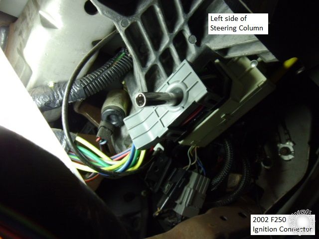
This is a picture of the main ignition connector on the drivers side of the steering column. Use a 7mm socket to remove
the retaining bolt.
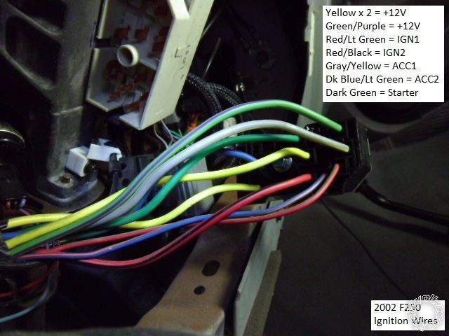
Here is a close-up of the main ignition connector. ( Please note that the chart shows how the wires were connected /
powered from the R/S. This wiring allowed the truck to remote start and run the heat / AC with no CEL's. ) As always, use your
DMM to locate, test and identify all wires.
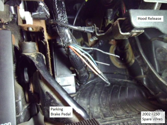
On the Super Duty trucks, Ford adds 4 wires to a harness that goes into the engine compartment. These wires are
typically used for snow plows, winches, etc. If these wires have not already been used, you can use them for the Tach
and Hood Pin wires. Below is a picture of these wires under the dash.
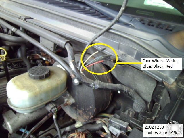
This is photo of the wires in the engine compartment.
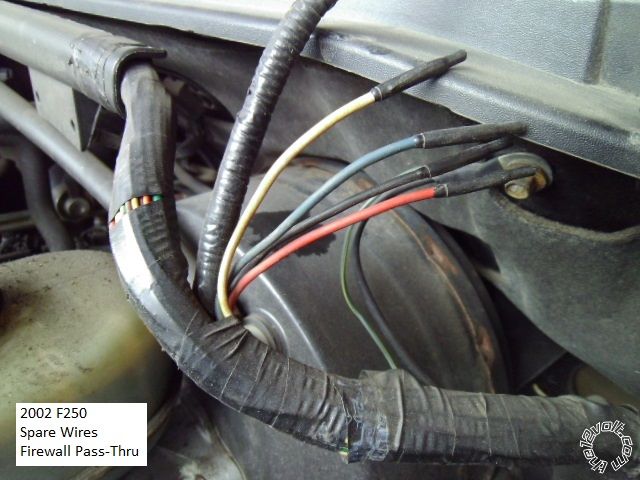
And a close-up.
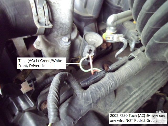
This is a picture of a Tach wire.
If your truck has the PATS immobilizer system ( very rare ), there are many good bypass modules available. Popular choices are the PKALL,
Fortin KeyOverRideAll, iDatalink ADS TBSL KO and ( my favorite ) Directed 1100F.
-------------
Soldering is fun!
you can also obtain positive parking light(brown) and negative horn(dark blue) wiring at the backside of the fusebox, rightmost connector if i recall. the three wire connector, plugged into the shift interlock solenoid, also has the brake switch signal (light green).
mark
Good info, much safer than getting the horn at the steering column and you have the fuse box pulled out anyway.
-------------
Soldering is fun!
Kreg: Would it be possible to show pics of how you add the isolation diode to your relay..
I am having a hard time seeing how to do this in a neat and tidy way.
Thanks.
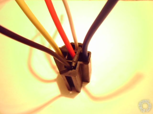
Here is one way to add the relay coil quenching diode. First, identify the relay coil input
leads. In this case the Black wire is Pin 85 and the White wire is Pin 86.
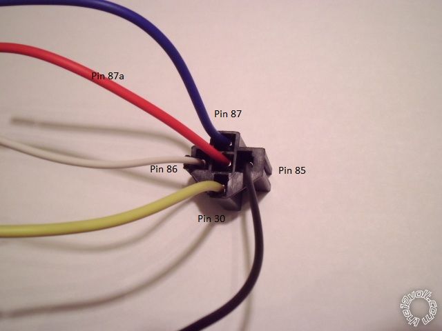
The standard relay convention has Pin 85 as (-) and Pin 86 as (+). This is important for proper
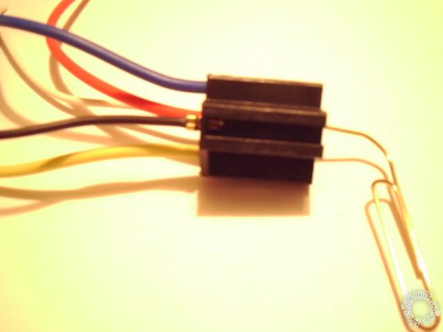
diode orientation. Next use a heavy paper clip or thin brad ( finish nail ) to depress the pin's
latch and release / remove the two coil pins.
These are the parts used : one diode ( 1N4004 or 1N4007 ), one short piece of 1/8" diameter
heat shrink tube, cut to length.
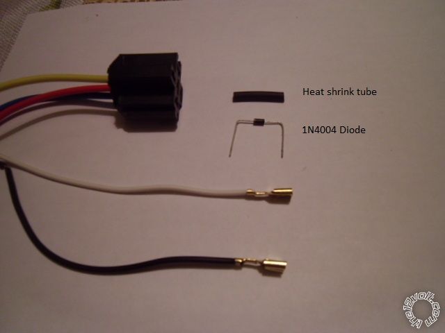
Judge the gap between the relays Pin 85 to Pin 86 and cut the heat shrink tube to proper
length. Note the diodes band marking, this will be the side connected to Pin 86. Bend one
leg of the diode centered at the correct gap length and install the heat shrink tube over the
diode. Bend the other leg of the diode and shrink the tube. Bend the diodes legs around
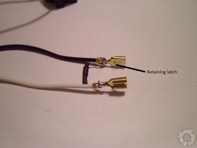
the two pins ensuring proper diode orientation and leg length. Make sure the pins' retaining
latch is inward, then solder each diode leg to the pin. Here is the result prior to relay connector
re-insertion.
Finished relay harness connector .
Once the quenching diode is added, the relay's coil becomes "polarity sensitive" and Pin 85 must receive
the (-) input and Pin 86 must receive the (+) input.
-------------
Soldering is fun!
Wow ,that looks great. I have never used the diodes before, but I think I will in the future. Thanks for the lesson.
Very clean job on the relay kreg. Never thought to depin them, I always added them inline on the wire from the alarm/rs.
Nice relay setup. Thanks for the photos and details. I printed it all and put it in my book of stuff to remember. Nice work.
-------------
When all else fails, Read the Instructions
Support the12volt.com Make a Donation
I know how a quenching diode works but have never used one unless it comes in a relay harness. My questions is what do you use these for in the 12 volt industry and how often do you use them. Should they be used on every relay?
-------------
I drink current, eat ohms, and bleed voltage
That is a controversial topic. Some installers never use a quenching diode on a relay and might never
have a come-back. Some R/S systems have some sort of limited circuit protection that might prevent
the relay coils collapsing pulse from causing a problem. With older R/S systems, some installers put
a diode on every output connection, relay or not.
My thoughts are "it depends". ( Please forgive me, Howard. ) If I'm using the R/S's 30 Amp relay Accessory
output to drive two ( or more ) relays to supply 30 Amp Accessory outputs for vehicle needs, then the diode
is not necessary. If I'm using the R/S's (-) 200 mA Parking Light output to drive a relay ( for polarity change or
Rt / Lt side vehicles ), then yes. The R/S's Parking Light output of quick, multiple flashes will create a good pulse.
While the 1N4007 diodes are very inexpensive when bought in packages of 200 ( or more ), it is time consuming
to add them to the 5 wire relay harness. A job for slow days during the off season. I figure it's cheap insurance.
I still like Mr. I Am An Idiots very graphic demonstration on Page 2 of this post :
https://www.the12volt.com/installbay/forum_posts.asp~TID~119158~PN~2~TPN~2 That should convince the
non-believers out there, but remember "Don't let your children try this at home..."
-------------
Soldering is fun!