2001-2003 F-150 Remote Start w/Keyless Pictorial
Printed From: the12volt.com
Forum Name: Car Security and Convenience - Alarm/Remote Start Pictorials
Forum Discription: Installer submitted Alarm, Keyless Entry, and Remote Start Pictorials from our Car Security and Convenience forum.
URL: https://www.the12volt.com/installbay/forum_posts.asp?tid=134275
Printed Date: May 23, 2026 at 12:23 AM
Topic: 2001-2003 F-150 Remote Start w/Keyless Pictorial
Posted By: kreg357
Subject: 2001-2003 F-150 Remote Start w/Keyless Pictorial
Date Posted: May 25, 2013 at 1:41 PM
This is a DIY Pictorial guide for installing a remote start with keyless entry system into
a 2001 Ford F150 pickup truck. The 2001 thru 2003 models should be the same.
There are a few slight variations between the trucks. All have a PATS engine immobilizer
system. The trucks with Factory Remote Keyless Entry have Type B (-) locks while trucks
without Factory RKE are Type C ( REV ) locks. Tach location will vary with the engine. This
truck had the 5.4 L Triton V-8, an automatic transmission, Factory RKE and no Factory Alarm.
For this install an Ultra Start U1272 system was used. For the PATS bypass a Directed
1100F bypass module was the choice. If this truck did not have Factory RKE, a Directed
451M door lock module would have been used to handle the locks. Additional parts
included a 30/40 Amp SPDT relay ( for Accessory3 ), a tilt switch for the hood pin and the
regular solder, heat shrink tube, electric tape, tie wraps, 1N4007 diode, etc.
Disassembly :
With the engine off, insert the ignition key to ON and place the gear shift selector to the L
range. Tilt the steering column to the lowest position and remove the upper bezel trim piece
by pulling it straight away from the instrument panel. Return the trans selector to Park and
remove the key. Tilt the steering wheel back to the top position. Remove the fuse panel cover.
Remove the lower dash panel by removing the fasteners shown in the photo below :
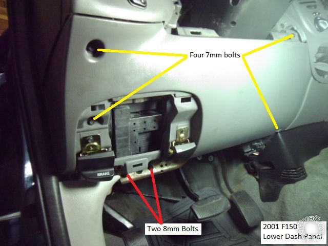
You can also remove the parking brake release and hood release by removing the two
7mm screws that retain each to the dash panel. There is no need to remove the steering
column trim.
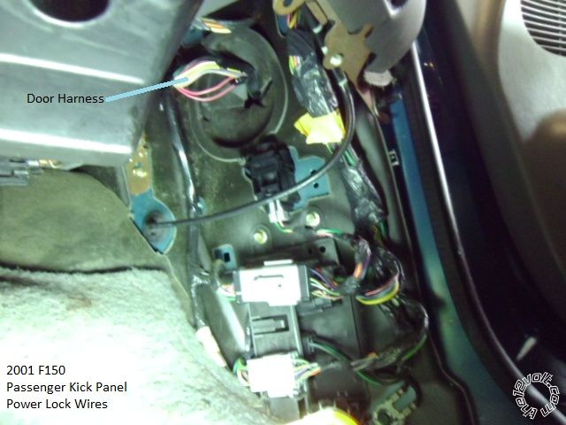
Remove the passenger door sill trim piece by lifting it straight up. Then remove the
Passenger kick panel by pulling in straight back. This is an easy place to locate the door
lock wires.
Wiring :
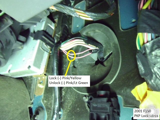
High up in the PKP is the door harness. Factroy RKE or not, it has the Pink / YELLOW Lock
and Pink/Light Green Unlock wires. Test to determine which system is in the truck.
If your truck has Factory RKE, you can also get these wires at the GEM module. The GEM
module is mounted to the firewall behind the fuse box under the drivers dash. If you
have the GEM module, test to see if GEM Wake-Up is necessary. ( GEM Wake-Up is not
covered in this Pictorial, sorry. )
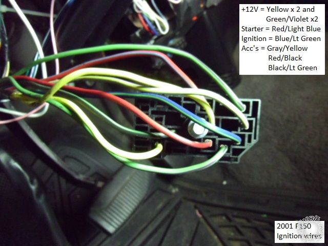
On the left side of the steering column is the main ignition connector shown below :
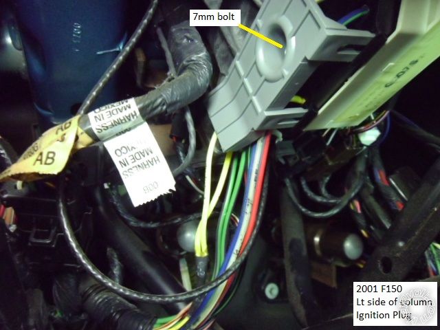
Use a 7mm socket wrench to remove the retaining bolt. The photo below shows the
ignition connector with the gray cover removed and all wires marked.
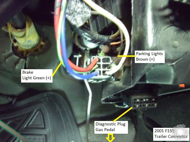
Ford makes the Parking Lights and Brake wires easy for you. They are located in the
trailer harness connector that is to the right of the steering column by the diagnostic
connector. Here is the connector with the wires indicated :
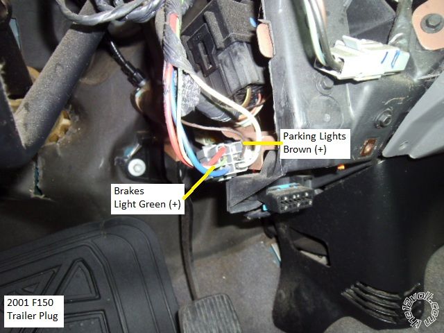
The Parking Lights can also be found at the Headlight Switch and the Brake wire
can be found at the top of the brake pedal, same wire colors.
The horn trigger wire is shown in the next picture. These connectors are just to the
right of the steering column.
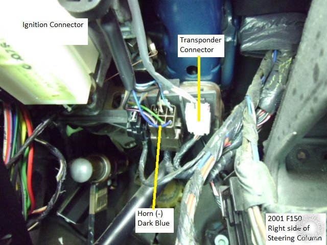
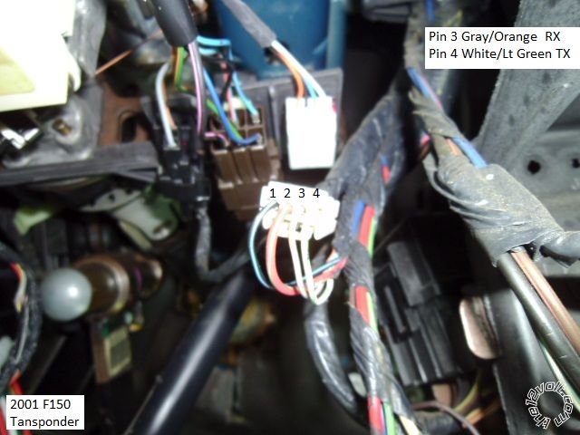
In the above picture the transponder connector is shown. The bypass connections
will be made on the lower harness, not the harness that comes from the ignition switch
cylinder. Note that the wire colors change at the connectors. Below is a photo of the
transponder connector, unplugged, with the wires marked.
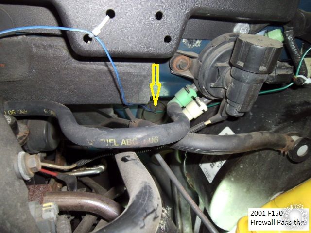
For the Tach and Hood Pin wires, firewall pass-thru can be made at this factory grommet
located above the gas pedal.
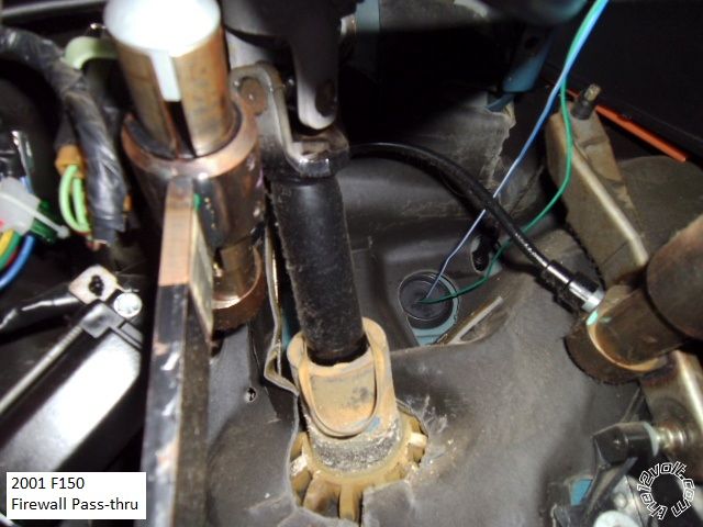
Here is a photo of the engine side of the pass-thru :
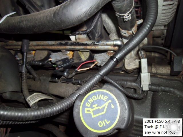
There are several places to get a Tach signal. The ECM is difficult due to it's location behind
the battery. A spark coil can be used if your R/S system can learn the weak ( 0.55V AC @ idle
and 0.75V AC @ 2500 RPM ) signal. A better choice is a F.I. which provides 1.6V AC @ idle and
2.7V AC @ 2500 RPM. Here is a photo of the F.I. wire at the passenger side front cylinder.
Any quality remote start system can be used. There is plenty of room under the dash to locate
and secure the system. There are several good bypass modules available for this truck and
only one key is needed to program the bypass. The 1100F bypass module is discontinued
( but available ). Other good choices include the Fortin Key-OverRide-All and it's cousin, the
XpressKit PKALL and from iDatalink, in the Solo series, are the ADS TBSL KO and the ADS TBSL TI.
For more info on GEM Wake-Up, see DEI Tech Tip #1093 which is in this ZIP file.
https://www.the12volt.com/installbay/file.asp?ID=1076
Remember, this is just a guide. Always test all wires with a Digital Multi Meter prior to making
your proper soldered connections. ------------- Soldering is fun!
Replies:
Posted By: smokeman1
Date Posted: May 25, 2013 at 9:56 PM
Once again, Real Nice Work and Pictorial....Can I adopt you? ------------- When all else fails, Read the Instructions
Support the12volt.com Make a Donation
Posted By: rheckbert3
Date Posted: November 30, 2013 at 1:54 PM
Kreg357, I used this post to install the Ultra Start and Fortin bypass in my 1999 F150 as you know because you helped me so much in my thread. Would you mind if I used these pictures and a few of my own to make a more in-depth pictorial on the12volt for 1997-2003 F150s?
Ricky
Posted By: kreg357
Date Posted: November 30, 2013 at 2:15 PM
Hi Ricky,
Glad this helped. Absolutely, feel free to use any pictures you think will add to your Pictorial. This is a popular truck and assisting other DIYer's is what this forum is all about! 
Kreg ------------- Soldering is fun!
Posted By: ace_boy2099
Date Posted: May 30, 2014 at 11:23 AM
OK, A couple questions; rheckbert3, You did your 99 F150, (ever get your walkthrough/Pictorial done?) What style? 2-door or 4 with or without RKE, etc... I have a 99 F150 SuperCab Lariat with the 4.6 (I believe it has RKE but I don't have remotes or a keypad)I'm gonna need to do this on soon and want to find out if all the wire colors and such matched up. I noticed on the Wiring Diagram/chart section they have 2 pages for the 99 F150 with a couple color differences, anyone know what those differences are? is one early 99 and the other late, or something else?
Does anyone know what kind of computer/device I could use to remove the PATS from the vehicles computer, I'd kind of rather do that if it's even possible, I'm not really looking forward to having to mess with bypass modules... unless I can find a blade module to put in the Compustar, that'd be a little cleaner.
While I'm in the dash I have to pull the cluster and re-solder the odometer so the d*** display stays on.
Posted By: kreg357
Date Posted: May 30, 2014 at 5:17 PM
Here is a link to rheckbert3's Pictorial : https://www.the12volt.com/installbay/forum_posts.asp?tid=135434 Doesn't look like he has
visited the site since last December.
It should be fairly easy to determine the power lock system ( Type B or Type C ) using a DMM to test the wires in the PKP.
For the added security, I would keep the PATS1 engine immobilizer system intact and use an inexpensive bypass module like the Directed
1100F that is typically available for under $20.
-------------
Soldering is fun!
Posted By: rheckbert3
Date Posted: June 11, 2014 at 11:45 PM
ace_boy2099 wrote:
OK, A couple questions; rheckbert3, You did your 99 F150, (ever get your walkthrough/Pictorial done?) What style? 2-door or 4 with or without RKE, etc... I have a 99 F150 SuperCab Lariat with the 4.6 (I believe it has RKE but I don't have remotes or a keypad)I'm gonna need to do this on soon and want to find out if all the wire colors and such matched up. I noticed on the Wiring Diagram/chart section they have 2 pages for the 99 F150 with a couple color differences, anyone know what those differences are? is one early 99 and the other late, or something else?
Does anyone know what kind of computer/device I could use to remove the PATS from the vehicles computer, I'd kind of rather do that if it's even possible, I'm not really looking forward to having to mess with bypass modules... unless I can find a blade module to put in the Compustar, that'd be a little cleaner.
While I'm in the dash I have to pull the cluster and re-solder the odometer so the d*** display stays on.
Hey yes it has been a long time Kreg357, I was at school, but I am back now. Kreg357 has the link to my picturial posted above but I used a 1999 F150 5.4L 4WD (4 door - 2 suicide doors).
I would suggest that you leave the PATS system intact and buy a bypass unit. It really was'nt to hard to install and in my opion makes the whole system much more cleaner than trying to remove the PATS system (if thats even possible). I used the Fortin Bypass module I think it was like 40$ or less on ebay. Let me know if you have any more questions and I will try to be on here more now that the semester is over for the summer.
I would suggest reading through the manual to the remote start system and the bypass module as well as the color code charts on here a few times before getting started. I spent a couple of days ahead of time just researching as much as I could before I even got started.
Goodluck! (assuming you haven't finished it in that past 2 weeks)
Ricky
Posted By: ace_boy2099
Date Posted: June 14, 2014 at 4:40 PM
Out of curiosity, if there is currently an alarm/starter with bypass and whatnot, if I was to take that out and install a new alarm/starter and use the same bypass I wouldn't have to re-program anything right, It'd be the same as disconnecting the battery wouldn't it, or is it the alarm that stores the bypass info and the bypass just does the talking?
The old alarm would be a Compustar P2W900FM-AS (CM5000 brain/controller) and the new would be a 2W9000SS (CM6000) unit. I don't know what the existing bypass would be, the "Pros" did it and left a rats nest under the column that I now have to sort out to re-do it for a couple reasons, One being that the alarm is for some reason draining the battery (of the truck), and another is that I can't seem to find my main set of keys for the truck with the LCD Remote and instead of paying 130.00 for a new remote to an old and problematic (battery draining) system I'd just install a newer system I have laying around the place.
Posted By: rheckbert3
Date Posted: June 15, 2014 at 1:42 AM
ace_boy2099 wrote:
Out of curiosity, if there is currently an alarm/starter with bypass and whatnot, if I was to take that out and install a new alarm/starter and use the same bypass I wouldn't have to re-program anything right, It'd be the same as disconnecting the battery wouldn't it, or is it the alarm that stores the bypass info and the bypass just does the talking?
The old alarm would be a Compustar P2W900FM-AS (CM5000 brain/controller) and the new would be a 2W9000SS (CM6000) unit. I don't know what the existing bypass would be, the "Pros" did it and left a rats nest under the column that I now have to sort out to re-do it for a couple reasons, One being that the alarm is for some reason draining the battery (of the truck), and another is that I can't seem to find my main set of keys for the truck with the LCD Remote and instead of paying 130.00 for a new remote to an old and problematic (battery draining) system I'd just install a newer system I have laying around the place.
The bypass is what stores the information and talks to the PATS system. When you trigger the remote start system to start the truck the remote starter tells the bypass to talk to the truck and "tricks" the truck into thinking someone has inserted a PATS key into the ignition with a code that matches the correct code in the truck. The bypass is basically just a clone of a key that sends the code to the truck when the remote starter tells it to.
I don't believe that you would have to reprogram the bypass as long as it is already programmed to the correct key. (In fact I believe some bypass systems only let you program them once for security reasons and to deter someone from stealing your bypass unit).
Ricky
Posted By: mtp2
Date Posted: November 03, 2015 at 5:22 PM
I have a 2003 f150 triton v8 everything in this pictorial matches mine except the transponder connector but that's all that's diffrent so far. I have my remote starter hooked up and literally EVERYTHING works except my parking lights, is there something special I need to have hooked up in order for my remote starter to be able to use my parking lights? I'd like them to at least flash when it starts so I have some sort of visual cue that it's on.
Posted By: kreg357
Date Posted: November 04, 2015 at 7:20 PM
Are you connected to the Brown (+) Parking Light at the trailer plug? Is there some strapping on your R/S system to select a positive (+) Parking Light output?
On some Viper systems there is an internal jumper / fuse that selects (+) or (-) Parking Lights. It usually comes loose during shipment... ------------- Soldering is fun!
Posted By: rheckbert3
Date Posted: November 04, 2015 at 11:07 PM
Hmm that's interesting that everything works expect the parking lights. Definitely make sure your connected to the brown parking light wire like Kreg357 said (same connector that you attached the brake shut down wire to the green wire)
Ricky
Posted By: brainsucker
Date Posted: November 05, 2015 at 8:26 PM
clifford 5102x no remote start......keep getting error code w/7 flashes...97 Ford f-150....not sure if i am programming the remote as well.......brake light wire is correct....both the green and purple wires are connected to the starter.....is that my mistake?the only manual i have is what ive found on the net....any advice would be appreciated
Posted By: brainsucker
Date Posted: November 05, 2015 at 11:22 PM
update to my post........went thru and checked myself....RED / RED / WHITE/ RED / black 12v constant...pink acc...tach at WHITE/ pink at pcm.......looked at the box alarm came in.....sez REFURBISHED in big ass letters...and i think i am locked out of the programming mode........can a shop with a bitwriter program my remotes?......also programmed tach signal.....tried virtual tach......i think the programmer has me locked out because i cant get 2 chirps for option 2 in menu 3..to disable manual trans mode...help me?
Posted By: kreg357
Date Posted: November 06, 2015 at 5:21 AM
A while ago, I heard that refurb units ( never use them myself ) were coming through with the remote and programming locked. Yes,
someone with a Bitwriter can change those settings and unlock the unit.
Here is how the thick wire ignition harness should look ( using H3 plug on a Viper 5601 ) :
H3/1 PINK (+) IGNITION 1 INPUT/OUTPUT dk. blue/lt. green (+) ignition switch, black 15 pin plug, pin I1
H3/2 RED / WHITE (+) FUSED (30A) FLEX RELAY lt. GREEN/ purple (50A) (+) ignition switch, black 15 pin plug, pin B4 *
H3/3 ORANGE ACCESSORY OUTPUT gray / YELLOW + ignition switch, black 15 pin plug, pin A4
H3/4 VIOLET (+) STARTER OUTPUT (CAR SIDE) \ RED / lt. blue + ignition switch, black 15 pin plug, pin STA
H3/5 GREEN (+) STARTER INPUT (KEY SIDE) / cut RED / lt. blue + ignition switch, black 15 pin plug, pin STA
H3/6 RED (+) FUSED (30A) IGNITION 1 INPUT lt. GREEN/ purple (50A) (+) ignition switch, black 15 pin plug, pin B4 *
H3/7 PINK/WHITE (+) IGNITION 2 / FLEX RELAY OUTPUT RED / black + ignition switch, black 15 pin plug, pin A3 ** set to ACC
H3/8 PINK/BLACK FLEX RELAY INPUT 87A FLEX RELAY not used
H3/9 RED / BLACK (+) FUSED (30A) ACC/STARTER INPUT lt. GREEN/ purple (50A) (+) ignition switch, black 15 pin plug, pin B4 *
H3/10 NC (no connection)
* Check to see if there are multiple Light GREEN/ Purple wires and/or Yellow wires at the ignition switch connector that test as +12V
constant and split the R/S's load ( 4 red, RED / xx wires ) amongst them.
If the truck has Rear ABS, there will be a Light/Blue Pink wire at the ignition switch plug that should be powered during a remote start
as an Ignition type wire. Obtain an addition 30/40 Amp SPDT relay w/harness and an in-line fuse holder with 25 Amp fuse.
Wire as follows :
Relay Pin 86 and 87 to +12V constant through 25 Amp fuse
Relay Pin 85 to Clifford thin PINK (-) 200mA IGNITION 1 OUTPUT ( on Remote Start aux plug ? )
Relay Pin 30 to Light/Blue Pink at ignition switch harness
Relay Pin 87a not used ------------- Soldering is fun!
Posted By: brainsucker
Date Posted: November 06, 2015 at 1:55 PM
so i should have the orange wire connected?......i thought this was to drive a relay or other acc......if it isn't connected.can that be what is keeping the r/s from working?.......gonna go try it anyway.....thanx kreg357
Posted By: kreg357
Date Posted: November 06, 2015 at 4:46 PM
Probably won't help. It should try to remote start without the Accessory wire connected. Seven flashes is Manual Trans Mode. You need to switch over to Auto Trans Mode. Do a search on that as there have been a few posts on the process using remotes. I have the BitWriter and avoid all of that.  ------------- Soldering is fun!
Posted By: brainsucker
Date Posted: November 07, 2015 at 3:52 AM
no luck on programming the remotes..........where can i get a bitwriter?.....as a mechanic i am always getting requests for audio installs and mods....i used to install at sound on wheels here in Huntsville AL......and a few other places as well......seems the older i get ....the more tools i need just to make a living......am currently working at home because i lost my D/L and lost my jo as well at a bmw dealer .......all in all..i am a diy that cant afford to pay someone to do what i should be able to do myself..any help or insight i can get is well appreciated.........maybe i can return the favor
Posted By: kreg357
Date Posted: November 07, 2015 at 2:43 PM
What you are looking for is a DEI 998T BitWriter. You can find them on EBay and some other online sources. Typical price is under &70. It's best to get one with the latest ROM version, now at V2.9. Think mine is at 2.7 but still does everything I need.
-------------
Soldering is fun!
Posted By: brainsucker
Date Posted: November 08, 2015 at 12:03 AM
thanx for your input kreg357............gonna take the truck to a dealer monday..........just a quick?.....i dont have door locks hooked up as of yet........think that would have anything to do with r/s not working?...i used to do installs bout 20+ years ago .......done a few r/s before......4 on my own cars....never installed a refurb tho....do they delete factory programming when repairing and adding new remotes?.seems possible where a diy cant do it without paying a dealer.......kinda sux cause now i look like an idiot in front of my customer.........owell..........thanx
Posted By: kreg357
Date Posted: November 08, 2015 at 5:01 AM
As mentioned, I have never tried a re-furb unit, so I'm not sure if they come locked and if the remotes are pre-paired with the brain.
I sometimes assume that everyone does an install the way I do. I always bench prep the R/S unit and connect all the necessary wires
to the vehicle during the install. I never do it in stages. Then I insert the fuses and start the programming sequences and testing.
Have you been able to change any options on the 5102? If not, perhaps you didn't connect the door trigger wire or it's not going to
a valid door trigger wire. Either way you can just disconnect it and use a jumper to ground for that programming step.
If you connected the Parking Light wire to the truck, do they flash when your try a lock or unlock? The lock wires don't have to be
connected yet. ------------- Soldering is fun!
Posted By: smokeman1
Date Posted: November 08, 2015 at 6:43 AM
I have used re-furb units before. All of the ones I have used were not locked and the remotes were paired to the units. I don't recall having a bad re-furb unit either. To date they are all working fine.
-------------
When all else fails, Read the Instructions
Support the12volt.com Make a Donation
Posted By: pentavolvo
Date Posted: November 08, 2015 at 11:20 AM
Used tons of refurbs. None were locked, all came paired and zero issues to date
Posted By: goldenlock
Date Posted: December 03, 2015 at 5:25 PM
This seems to be a great help who want a keyless entry system. In this the electronic lock controls access the vehicle without using a traditional mechanical key. It is important to carefully enter the self-programmed numeric code for entry. Nowadays, you will get two types of remote keyless systems, one which unlocks the doors, and the other which locks the engine.
-------------
Digital Marketing and Public Relations Manager at Golden Locksmith TX
Posted By: jared26
Date Posted: December 26, 2015 at 10:30 PM
Hey guys, good topic here with a lot of good info, actually wish I had seen it earlier, I would have been able to get the parking light and brake wires a little easier.
Heres my dilemma:
I got a Command Start CS888LCD2 for Christmas and spent the day trying to install it into my 2000 F150 Supercab.
I've got the unit hooked up for the most part, but I am having issues with the parking lights, door locks and the dome light.
It seems as my truck didn't have factory RKE, I grabbed the power door lock wires from the passenger kick panel, used a test light to see which is - and which is + and hooked them up to the corresponding wires in the harness for my remote start, I tried locking and unlocking the doors from the remote but the locks don't respond, on the door lock harness from my remote start there is a +12v output wire, where on the truck do I splice that in?
I also have the + dome light input going to the BLACK/ blue wire in the drivers kick panel but receive no response from the dome light when locking or unlocking the truck with the remote.
The last is the parking lights I have the brown wire from the headlight switch hooked up to the parking light wire on my remote start and the parking lights don't flash when hitting lock or unlock on the remote either, there is another fused wire coming from the harness on my remote start which is for polarity selection, how does that work? Do I hook it to ground or positive or ?
I got frustrated and called it a day so I haven't hooked up the tach input or hood switch so I haven't tried the remote start yet, I'll do that after I get this sorted out.
I should note that when you hit the unlock or lock button on the transmitter the horn honks once for unlock and twice for lock and you can hear relays clicking so it seems like its trying to do something but I get no response from the locks, dome light or parking lights.
Any help would be very much appreciated, I've done all types of work on vehicles and thought I could handle doing a remote start myself but it seems like it might be just a bit out of my realm of capability.
Posted By: kreg357
Date Posted: December 27, 2015 at 8:52 AM
If your truck did not come from the factory with Remote Keyless Entry, you have Type C locks, This will require a DEI 451M Door Lock Module or two relays and a fuse holder w/ 10 Amp fuse. Read up on the Type C Reverse polarity door locks and see diagrams with the Door Locks tab up above.
Never used the R/S system you have but with the Trucks (+) Parking Light Brown wire, that R/S Parking Light fused input wire should go to +12V constant so the output wire is (+).
Not familiar with your R/S system, but is the Dome Light Supervision out a (-) output? The truck is looking for a (+) on that BLACK/ Light Blue wire. You might need a relay to make the polarity conversion.
-------------
Soldering is fun!
Posted By: jared26
Date Posted: December 27, 2015 at 8:44 PM
Hi Kreg,
Thanks for the quick reply. It was snowing today so I didn't play with it. I ended up finding a diagram about the type C locks yesterday, if I can find a pats bypass that does the locks as well I might do that, otherwise I'll go the relay route.
I will try hooking that fused wire up to a 12v constant to see if that gets the parking lights working.
As far as the dome light input it is a + from the unit but I did just realize on the diagram it says dome light input as opposed to output, there is another wire for a - input but I don't see anything o the diagram for a dome light output. Hmmm
Posted By: jared26
Date Posted: December 28, 2015 at 11:31 PM
Made some progress today, I've now got the keyless entry working as well as the parking lights.
The dome light still isn't working so I'll have to look into that further.
The problem I have now is the remote start isn't starting the truck. I do have PATS but am going to do my own work around on that so for now I just tried starting it with the key in the ignition.
It will crank but not fire, if I move the key into the run position from off while its cranking it will fire and run just fine, I think I have one of the ignition wires run incorrectly as I don't hear it prime the fuel pump when using the remote start.
The way I have it wired is:
R/S Ignition switch
+12v input Light GREEN/ violet
2nd aux output Not wired
2nd aux input Not wired
Starter kill motor side Not wired
Starter kill key side Not wired
Ignition output + Dark blue/Light green
Heater A/C output + Gray / YELLOW
Starter output +RED / Light blue
+12v input Light GREEN/ Violet
Tach input WHITE/ Pink at PCM
The truck had an alarm or keyless module or something in it when I bought it and both +12v inputs were wired to the same light GREEN/ violet ignition switch wire so I just kept it the same way on this installation to cut down on new splices into the harness.
Theres also another 3 wire harness from the alarm that has accessory, ignition and start negative outputs, I'm not too sure where to wire those into.
Any and all help would be greatly appreciated. Thanks!
Posted By: kreg357
Date Posted: December 29, 2015 at 4:44 AM
Really need a Command Start CS888LCD2 Install Manual to help out. The truck has several Ignition / Accessory wires that should be powered during a remote start. You will need relays to use the R/S's (-) Accessory and (-) Ignition outputs to create the high current (+) outputs for the RED / Black and BLACK/ Light Green ignition wires. Additionally, due to the current draw, I would split the R/S's +12V inputs between the available supply wires in the trucks ignition harness. The added relays for the extra ignition circuits would also go to these ( unused ) +12V constant wires for their input power.
-------------
Soldering is fun!
Posted By: jared26
Date Posted: December 29, 2015 at 6:43 AM
Here's a scan of the install manual. If I don't need to run the - outputs I'd rather not, all I really want the truck to do when remote starting is run the HVAC.

Posted By: jared26
Date Posted: December 29, 2015 at 6:46 AM
Looks like the last link didn't work so here it is.
Thanks!
Posted By: kreg357
Date Posted: December 29, 2015 at 6:08 PM
OK. To power the extra ignition wires you will need two 30/40 Amp SPDT relays and the 5 pin harness plus an in-line fuse
holder with 20 Amp fuses and a couple of 1N4007 diodes. Wire as follows :
Relay 1 for IGN2 :
Relay Pin 85 to R/S IGN (-) Output Blue wire
Relay pins 86 and 87 to +12V constant through 20 Amp fuse
Relay Pin 30 to F150 RED / Black wire in ignition harness
Relay 2 for ACC2 :
Relay Pin 85 to R/S ACC (-) Output Brown wire
Relay pins 86 and 87 to +12V constant through 20 Amp fuse
Relay Pin 30 to F150 BLACK/ Light Green wire in ignition harness
Connect the diodes across each relay, pins 86 and 85, with the diodes band towards pin 86.
There are ample +12V constant wires at the main ignition plug to individually power each circuit. ------------- Soldering is fun!
Posted By: jared26
Date Posted: December 29, 2015 at 7:03 PM
Thanks again for your help. Do I have to add those relays in because there aren't enough outputs on this unit or was there another reason? Just asking out of curiosity as I'm new to all this.
Thanks
Posted By: jared26
Date Posted: December 29, 2015 at 7:09 PM
Oh, I see I should have read more carefully, thats to power the - outputs from the red 3 pin plug, I see what you're saying now.
Thank you
Posted By: kreg357
Date Posted: December 29, 2015 at 9:07 PM
Yes. The truck has many ignition wires that need to be powered during a remote start. The R/S unit has the capability to power some of them but not all. These vehicle circuits are designed / engineered to be separate circuits so they can't be tied together and powered by one R/S output. The R/S does have low current (-) ignition outputs that can be used to energize relays that in turn can supply high current (+) outputs for these vehicle circuits. Extra work but necessary to properly remote start the engine.
-------------
Soldering is fun!
Posted By: jared26
Date Posted: December 29, 2015 at 9:15 PM
I gotcha, that poses another question then, the R/S has a programmable 4th relay that I can set from acc +/- ign +/- or start +/- could I use that for one of them and just add one additional relay from one of the low current outputs to the ignition wiring?
Posted By: kreg357
Date Posted: December 30, 2015 at 3:54 AM
Didn't see that on the diagram but yes, if it is a high current selectable ignition type output, use the 4th relay ( flex output ) in lieu of an external relay.
-------------
Soldering is fun!
Posted By: jared26
Date Posted: December 30, 2015 at 3:58 AM
Thanks Kreg, I appreciate all your help, I'll try to wrap it up in the next few days and I'll let you know how it went.
Posted By: jared26
Date Posted: December 30, 2015 at 6:49 PM
So here's an odd update, this morning when I was waiting for the truck to warm up I set the R/S into tach learning mode, it went through its sequence to confirm that it did learn and then when I got to work this morning and shut the truck off it kept running. In the end I had to unplug the 9 pin main harness at the R/S to get the truck to shut off so now I'm going to have to figure out whats going on there.
Posted By: rheckbert3
Date Posted: December 30, 2015 at 6:54 PM
jared26 wrote:
So here's an odd update, this morning when I was waiting for the truck to warm up I set the R/S into tach learning mode, it went through its sequence to confirm that it did learn and then when I got to work this morning and shut the truck off it kept running. In the end I had to unplug the 9 pin main harness at the R/S to get the truck to shut off so now I'm going to have to figure out whats going on there.
Is your brake safety interrupt wire connected? The remote start system should have "shut down" after you put the key in the truck and pressed the brake pedal to shift into gear.
Ricky
Posted By: jared26
Date Posted: December 30, 2015 at 6:56 PM
Yes it is hooked up to the light green wire at the brake switch.
Posted By: jared26
Date Posted: January 02, 2016 at 8:05 PM
kreg357 wrote:
OK. To power the extra ignition wires you will need two 30/40 Amp SPDT relays and the 5 pin harness plus an in-line fuse
holder with 20 Amp fuses and a couple of 1N4007 diodes. Wire as follows :
Relay 1 for IGN2 :
Relay Pin 85 to R/S IGN (-) Output Blue wire
Relay pins 86 and 87 to +12V constant through 20 Amp fuse
Relay Pin 30 to F150 RED / Black wire in ignition harness
Relay 2 for ACC2 :
Relay Pin 85 to R/S ACC (-) Output Brown wire
Relay pins 86 and 87 to +12V constant through 20 Amp fuse
Relay Pin 30 to F150 BLACK/ Light Green wire in ignition harness
Connect the diodes across each relay, pins 86 and 85, with the diodes band towards pin 86.
There are ample +12V constant wires at the main ignition plug to individually power each circuit.
So im going to use the 4th relay in the r/s to do ACC2 do I only need to do a diode on my external relay? Thanks I'm going to hopefully get this tackled tomorrow.
Posted By: jared26
Date Posted: January 10, 2016 at 1:39 PM
I'm so close but the issue I'm having now is when I hook up the ignition output wire on the r/s to the dark blue light green ignition wire in the truck it completes a circuit and the airbag and battery light stay on in the cluster and the theft light flashes. I would appreciate any input.
Thanks
Posted By: kreg357
Date Posted: January 10, 2016 at 4:33 PM
Please list any R/S output or relay circuit that is connected to the F150's ignition wires. That seems to be where the problem is ( unless the off-brand R/S unit has a major issue ). It appears that there is an ignition wire problem - an output that is not working or not behaving as programmed. You might want to put a meter on these wires and verify that they are indeed working correctly.
-------------
Soldering is fun!
Posted By: jared26
Date Posted: January 10, 2016 at 5:09 PM
Ok, I've got the 12v constants hooked to the yellow and green violet wires in the ignition harness, acc1 at they grey / YELLOW wire, acc2 to the RED / BLK wire, starter output to red light blue/ and the ignition output wire stays hot all the time, I'm trying to hook it up to blue light green. I do also have a 12constant from the ignition wires to my relays for the power door locks and as the positive switch for my parking lights. If I cut the 12v to the door locks or take out the fuse for the parking light switch wire I still have the same problem so I don't believe that is causing it.
Posted By: jared26
Date Posted: January 10, 2016 at 5:16 PM
If I unhook one of the 12v wires the ignition wire in question goes dead. Should that 12v be hooked up to a switched 12v wire as opposed to a constant?
Posted By: kreg357
Date Posted: January 10, 2016 at 5:45 PM
No. The R/S unit should not allow +12 V out on its' thick Blue Ignition output wire unless the R/S is actually trying to R/S the truck. Something is wrong. Try removing the fuses for a few minutes to see if that resets it.
Do you have the thin Blue (-) Ignition Output wire from that 3 pin plug connected to anything?
Well, I've seen you worked on that brand before but here goes :
First, you are NOT set for Starter kill, so those wires are available.
The 2 Red wires go to +12V constant
The Green wire can be set to ACC2 and connected to the F150's RED / Black ACC2 wire.
The Yellow is not used. ( input )
The Purple wire is not used.
The Blue wire goes to the F150's Dark Blue/Light Green IGN1 wire.
The Brown wires goes to the F1`50 Grey / YELLOW ACC1 wire.
The Orange wire goes to the F150's RED / Light Blue Starter wire.
There will be a Light Blue/Pink IGN2 if equipped with rear ABS.
Extra relay for BLACK/ Light Green ACC3. ------------- Soldering is fun!
Posted By: jared26
Date Posted: January 10, 2016 at 5:55 PM
No, nothing from the thin blue wore, I set the programmable relay up and set it up as ignition to try and bypass putting any extra relays in. There is a note here on the manual for the programmable relay that the yellow is for the input +(-) so I have it hooked up to a 12v constant. Do I not need that even having the green set up for acc2?
Posted By: kreg357
Date Posted: January 10, 2016 at 6:07 PM
Think you might be correct on the Yellow wire. If you are using the Flex relay ( instead of as a Starter Kill relay ) then the Yellow is the input for the Green Output, so it goes to +12V constant. Not sure about the actual programming necessary.
But your problem is that the thick Blue wire is outputting +12V all the time, not just during a remote start. ------------- Soldering is fun!
Posted By: jared26
Date Posted: January 10, 2016 at 8:14 PM
OK, I will try hooking the yellow wire back up, I've gone into the programming options and set the flex relay as acc. I took the unit out of the truck and opened it up just to see take a look at the board and see if there were any obvious signs of damage but I noticed no burns or anything it all looked fine, plugged it back into the truck and now it won't try to remote start at all and that ignition wire isn't staying hot anymore. The remote start also has an on/off switch that you can use to disable the remote starter, I noticed that if I set it to off it would cut power to the ignition wire, switch it back to on and the ignition wire would stay hot all the time.
Posted By: kreg357
Date Posted: January 11, 2016 at 1:55 AM
You might have to do a Tach Learn again. That switch is like a Valet switch on normal brands.
-------------
Soldering is fun!
Posted By: bucky kessler
Date Posted: May 06, 2016 at 4:54 AM
Just had to register to add to this. I just completed my install and the problem I ran into was everything worked great but the heater would not turn on. Turns out I had the wrong acc wire. The wire you want for the heater is the gray / YELLOW wire. Hope this helps someone.
Posted By: rheckbert3
Date Posted: May 06, 2016 at 7:14 PM
bucky kessler wrote:
Just had to register to add to this. I just completed my install and the problem I ran into was everything worked great but the heater would not turn on. Turns out I had the wrong acc wire. The wire you want for the heater is the gray / YELLOW wire. Hope this helps someone.
Congratulations on the install! Yes grey / YELLOW wire is correct. Just out of my own curiosity, what was the second accessory wire you connected to other than grey / YELLOW (RED / black or black green?)
Posted By: rheckbert3
Date Posted: May 06, 2016 at 7:16 PM
bucky kessler wrote:
Just had to register to add to this. I just completed my install and the problem I ran into was everything worked great but the heater would not turn on. Turns out I had the wrong acc wire. The wire you want for the heater is the gray / YELLOW wire. Hope this helps someone.
Congratulations on the install! Yes grey / YELLOW wire is correct. Just out of my own curiosity, what was the second accessory wire you connected to other than grey / YELLOW (RED / black or black green?)
Posted By: bucky kessler
Date Posted: May 07, 2016 at 8:52 PM
I did BLACK/ green at first.
Posted By: 4thgencamarofan
Date Posted: October 29, 2017 at 11:49 PM
I know it's not covered in the first post, but does anyone have more info on the GEM wake up and diode isolation for door triggers to prevent false triggers? I'm looking at doing a Viper/Clifford 5906 remote start system on a 2002 Supercrew truck with FKE. I have a good understanding of the IGN, ACC, starter, parking lights, brake shutdown, horn, lock/unlock wires etc. First post makes it pretty easy lol. Only thing I'm not sure on is the GEM wake up and diode isolation.
Thanks
Posted By: geepherder
Date Posted: October 30, 2017 at 8:27 AM
https://diagrams.marktoonen.nl/DOWNLOADS/14301_F-SERIES-LIGHT-DUTY_FORD%20DOOR%20PIN%20ISOLATION.pdf
-------------
My ex once told me I have a perfect face for radio.
Posted By: 4thgencamarofan
Date Posted: October 30, 2017 at 12:20 PM
Okay so if I'm understanding this correctly.
Where the 4 door triggers come into the GEM(called BCM on that file) I need to cut them and put 1N4001 diodes on each of them with the stripe facing AWAY from the GEM.
And then when I connect the 4 door triggers to the instant trigger on the RS/alarm unit, I also need 1N4001 diodes on all four of those wires as well with the stripe facing away from the RS/Alarm unit.
Is this correct or do I have it all screwed up?
Posted By: 4thgencamarofan
Date Posted: October 30, 2017 at 12:43 PM
I also see in folder 1093 of that zip file there's info on GEM wake up. It says in there the GEM needs to see a factory remote, a door is opened, or the factory alarm disarm signal. Can I simply connect the RS/Alarm disarm signal to the factory alarm disarm signal since it has a factory alarm?
Posted By: 4thgencamarofan
Date Posted: November 06, 2017 at 3:52 PM
Can anyone confirm my question? I want to make sure I fully understand this before I purchase anything.
I would take the Viper/Python's green door trigger input and wire to each of the individual door triggers with a diode with the cathode side away from the alarm module. And then cut the wires going to the GEM and put diodes on each of those triggers with the cathode side away from the GEM. There's no trunk so that's not anything I need to mess with. This is how I'm interpreting DEI tech tip 1076 and the link geepherder posted for door trigger isolation.
GEM wake up as I understand it from DEI tech tip 1093.
I need to take the blue unlock wire from the alarm and wire it to the trucks unlock signal AND the door ajar wire using diodes on both with the cathode side toward the alarm module, and then set the alarm to double pulse unlock. The first pulse will wake up the GEM, and then the second pulse will actually unlock the vehicle.
Am I understanding this correctly?
Thanks for the help guys, I'm a newbie when it comes to stuff like this. I work on diesels, not much of a wiring guy but I do have a basic understanding.
Posted By: kreg357
Date Posted: November 06, 2017 at 8:27 PM
Yes, you have it correct. Follow the two TechTips using the correct vehicle wires and you are all set. 1N4001 diodes will be OK. I would solder everything.
Not sure how long it takes for the GEM to go to sleep. The Tech Tip says 2 minutes but I thought I saw something that said 30 minutes sometimes. Lock the truck and then see if it will unlock the next morning to be sure.
-------------
Soldering is fun!
Posted By: 4thgencamarofan
Date Posted: November 07, 2017 at 10:35 AM
Okay thanks Kreg. Yes I think it's longer than 2 minutes. I did the GEM wake up test and waited about 5 minutes and the locks unlocked the first time pushing the unlock button on the driver door. I didn't let it sit any longer than that and try it again but I'm sure GEM wake up is necessary since it has factory RKE.
And yes I plan on soldering all of my connections. I actually bought some solder when I was at Walmart last night.
|